Note: Descriptions are shown in the official language in which they were submitted.
1 STORAGE BUCKET ASSEMBLY
2 BACKGROUND OF THE INVENTION
3 1. Field of the Invention
4 The present invention relates to a storage bucket assembly, and more
particularly to a storage bucket assembly that can be hung and abut an edge of
6 a table.
7 2. Description of the Prior Art(s)
8 A conventional storage bucket is used for storing objects. Take wine
9 bottle storage for example. The conventional storage bucket for wine
bottles
has a flat inner bottom surface. Ice cubes can be stored in the conventional
11 storage bucket for cooling the wine bottle put in the conventional
storage
12 bucket, such that temperature of wine in the wine bottle can be
decreased,
13 improving the mouthfeel of cold wine drinking. The conventional storage
14 bucket is usually put on a table for users to easily take the wine
bottle from the
conventional storage bucket.
16 However, the conventional storage bucket put on the table occupies
17 quite a lot of space on the table. Moreover, due to condensation formed
on an
18 outer sidewall of the conventional storage bucket, the table becomes wet
and
19 messy. For increasing the available space on the table and keeping the
table tidy,
the conventional storage bucket may be put on the ground instead. When the
21 conventional storage bucket is put on the ground, the users need to
stoop to
22 take the wine bottle from the conventional storage bucket. Furthermore,
when
23 put on the ground, the conventional storage bucket is not easily
noticeable and
24 is prone to be collided by the users.
CA 3013378 2018-08-03
2
1 To overcome the shortcomings, the present invention tends to provide a
2 storage bucket assembly to mitigate or obviate the aforementioned
problems.
3 SUMMARY OF THE INVENTION
4 The main objective of the invention is to provide a storage bucket
assembly that may solve the problems that the conventional storage bucket put
6 on the table occupies too much space above the table-top surface, the
7 condensate water drops on the outside of the conventional storage bucket
stain
8 the table-top surface, the conventional storage bucket put on the ground
is
9 prone to be collided, and the wine bottle in the conventional storage
bucket on
the ground is hard to retrieve.
11 The storage bucket assembly has a bucket and a hanging member. The
=
12 bucket has a bucket body, two connecting portions, and an abutting
portion.
13 The bucket body has a top, an outer surface, a front side, a chamber,
and an
14 opening. The chamber of the bucket body is formed in the bucket body.
The
opening of the bucket body is formed on the top of the bucket body and
16 communicates with the chamber of the bucket body. The two connecting
17 portions are formed on the outer surface of the bucket body at a spaced
interval.
18 The abutting portion is disposed on the top of the bucket body and is
disposed
19 adjacent to the opening of the bucket body. The hanging member is
pivotally
mounted on the bucket and has two connecting plates, a top plate, and two
21 supports. The two connecting plates are respectively connected pivotally
to the
22 two connecting portions of the bucket and each of the connecting plates
has a
23 top end. The top plate spans the opening of the bucket body, is
connected to the
24 two top ends of the two connecting plates, and has a bottom surface, a
back
CA 3013378 2018-08-03
3
1 -- side, and two supporting portions. The two supporting portions are formed
on
2 -- the bottom surface of the top plate at a spaced interval and are adjacent
to the
3 -- back side of the top plate. The two supports are mounted on the bottom
surface
4 -- of the top plate and are respectively disposed at the two supporting
portions.
In use, the storage bucket assembly is hung down from an edge of a
6 -- table with the hanging member disposed on the edge of the table. When the
7 -- storage bucket assembly is located beside the edge of the table, the
storage
8 -- bucket assembly occupies very little space on a top surface of the table
and
9 -- keeps the top surface of the table tidy. The two supports and the
abutting
-- portion are formed as a three-point support to make the storage bucket
11 -- assembly steadily mounted on the edge of the table. The two connecting
plates
12 -- can sway relative to the bucket body to adjust the angle between the
bucket and
13 -- the hanging member. The storage bucket assembly can be applied to tables
of
14 -- different thicknesses.
Other objects, advantages and novel features of the invention will
16 -- become more apparent from the following detailed description when taken
in
17 -- conjunction with the accompanying drawings.
18 -- BRIEF DESCRIPTION OF THE DRAWINGS
19 Fig. 1 is a perspective view of a storage bucket assembly in accordance
-- with the present invention;
21 Fig. 2 is another perspective view of the storage bucket assembly in
Fig.
22 -- 1;
23 Fig. 3 is a perspective view of the storage bucket assembly in Fig. 1,
24 -- showing a hanging member swaying forward away from limiting stoppers;
CA 3013378 2018-08-03
4
1 Fig. 4 is a top view of the storage bucket assembly in Fig. 1;
2 Fig. 5 is a side view of the storage bucket assembly in Fig. 1;
3 Fig. 6 is an enlarged front view in partial section of the storage
bucket
4 assembly in Fig. 1;
Fig. 7 is an operational cross-sectional side view of the storage bucket
6 assembly in Fig. 1, showing the hanging member abutting an edge of a
table;
7 Fig. 8 is an operational front view of the storage bucket assembly in
8 Fig. 7;
9 Fig. 9 is an operational cross-sectional side view of the storage
bucket
assembly in Fig. 7, showing a wine bottle and ice cubes put in the storage
11 bucket assembly;
12 Fig. 10 is another operational cross-sectional side view of the storage
13 bucket assembly in Fig. 7, showing the wine bottle and the ice cubes put
in the
14 storage bucket assembly; and
Fig. 11 is an operational side view showing two storage bucket
16 assemblies of Fig. 1 stacked together.
17 DETAILED DESCRIPTION OF THE PREFERRED EMBODIMENTS
18 With reference to Figs. 1 to 3, a storage bucket assembly in accordance
19 with the present invention comprises a bucket 10 and a hanging member
20.
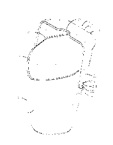
With reference to Figs. 2 to 4, the bucket 10 has a bucket body 11, two
21 connecting portions 12, and an abutting portion 13. The bucket body 11
has a
22 top, an outer surface, a front side, a chamber 14, and an opening 15.
The
23 chamber 14 is formed in the bucket body 11. The opening 15 of the bucket
24 body 11 is formed on the top of the bucket body 11 and communicates with
the
=
CA 3013378 2018-08-03
5
1 chamber 14 of the bucket body 11. The two connecting portions 12 are
formed
2 on the outer surface of the bucket body 11 at a spaced interval.
Specifically, the
3 connecting portions 12 are oppositely disposed on the outer surface of
the
4 bucket body 11. The abutting portion 13 is disposed on the top of the
bucket
body 11 and adjacent to the opening 15 of the bucket body 11. Preferably, the
6 abutting portion 13 is made of silica gel and provides a good anti-slip
effect.
7 Furthermore, the bucket body 11 has two limiting stoppers 16. The
8 limiting stoppers 16 are formed on the bucket body 11 and are disposed
behind
9 the two connecting portions 12 respectively. In addition, the bucket body
11
has an inner bottom surface, a positioning protrusion 17, and a raising
11 protrusion 18. The inner bottom surface is formed in the bucket body 11.
The
12 positioning protrusion 17 is formed on the inner bottom surface of the
bucket
13 body 11 and protrudes to the chamber 14 of the bucket body 11. The
raising
14 protrusion 18 is formed on the inner bottom surface of the bucket body
11 and
is located between the positioning protrusion 17 and the front side of the
bucket
16 body 11.
17 With reference to Figs. 1, 2, and 5, the hanging member 20 is pivotally
18 mounted on the bucket 10 and has two connecting plates 21, a top plate
22, and
19 two supports 23. The two connecting plates 21 connect pivotally to the
two
connecting portions 12 of the bucket 10, respectively. Each of the connecting
21 plates 21 has a top end. The top plate 22 spans the opening 15 of the
bucket
22 body 11, are connected to the two top ends of the two connecting plates
21, and
23 has a bottom surface, a back side, a front side, and two supporting
portions 24.
24 The two supporting portions 24 are formed on the bottom surface of the
top
CA 3013378 2018-08-03
6
1 plate 22 at a spaced interval and are adjacent to the back side of the
top plate 22.
2 Furthermore, the top plate 22 has an indentation 25 formed in the front
side of
3 the top plate 22. The two supports 23 are mounted on the bottom surface
of the
4 top plate 22 and are respectively disposed at the supporting portions 24.
Preferably, the two supports 23 are made of silica gel and provide a good
6 anti-slip effect. In addition, the two limiting stoppers 16 are
respectively
7 disposed behind the two connecting plates 21, and selectively abut
against the
8 two connecting plates 21 to prevent the two connecting plates 21 from
further
9 swaying backward.
With reference to Figs. 5 and 6, each of the two connecting plates 21
11 has a pivot hole 211 and an expansion gap 212. The pivot hole 211 is
formed
12 through the connecting plate 21 and adjacent to a lower end of the
connecting
13 plate 21. The expansion gap 212 is formed through the connecting plate
21 and
14 communicates with the pivot hole 211. Each of the two connecting
portions 12
has a shaft 121 and a limiting plate 122. The shaft 121 is formed on the outer
16 surface of the bucket body 11 and is pivotally mounted in the pivot hole
211 of
17 a corresponding one of the connecting plates 21. The limiting plate 122
is
18 formed on the shaft 121 and holds the corresponding one of the
connecting
19 plates 21 between the limiting plate 122 and the bucket body 11.
With reference to Fig. 7 and 8, to dispose the storage bucket assembly
21 on an edge of a table 30, the two supports 23 on the top plate 22 abut
against a
22 top surface of the table 30 and the connecting plates 21 abut against
the edge of
23 the table 30. Thus, the hanging member 20 is hung on the edge of the
table 30.
24 With the two connecting plates 21 of the hanging member 20 pivotally
CA 3013378 2018-08-03
7
1 connected to the two connecting portions 12 of the bucket 10, the bucket
10
2 that is hung down from the Connecting plates 21 of the hanging member 20
will
3 sway until the abutting portion 13 abuts against a bottom surface of the
table 30.
4 The two supports 23 that contact the top surface of the table 30 serve as
supporting points for hanging the bucket 10. The abutting portion 13 that
abuts
6 against the bottom surface of the table 30 prevents the bucket body 11
from
7 shaking. The two supports 23 and the abutting portion 13 are formed as a
8 three-point support to make the storage bucket assembly steadily mounted
on
9 the edge of the table 30. Accordingly, the storage bucket assembly can be
steadily disposed on the edge of the table 30.
11 With reference to Figs. 7 to 9, when the storage bucket assembly is in
12 use, the storage bucket assembly is disposed on the edge of the table 30
and a
13 wine bottle 40 is put into the chamber 14 of the bucket body 11. Ice
cubes 42
14 are also put into the chamber 14 of the bucket body 11 and are spread
around
the wine bottle 40 for cooling the wine bottle 40. A bottom surface of the
wine
16 bottle 40 is put on the positioning protrusion 17 of the bucket body 11
with the
17 positioning protrusion 17 protruding into a recess formed on the bottom
surface
18 of the wine bottle 40 for positioning the wine bottle 40. The raising
protrusion
19 18 raises a part.of the bottom surface of the wine bottle 40 and the
wine bottle
40 tilts toward the hanging member 20. Thus, the wine bottle 40 leans on the
21 top plate 22 and is mounted in the indentation 25 of the top plate 22.
The
22 indentation 25 of the top plate 22 allows the top plate 22 to stably
hold the wine
23 bottle 40 at a specific position, such that the wine bottle 40 is stably
mounted in
24 the chamber 14 of the bucket body 11. The storage bucket assembly that
is
CA 3013378 2018-08-03
8
I disposed on the edge of the table 30 occupies very little space above the
top
2 surface of the table 30, and keeps the top surface of the table 30 tidy.
3 Accordingly, aesthetic appeal of the top surface of the table 30 is
improved.
4 With reference to Figs. 9 and 10, the storage bucket assembly can be
.5 disposed on the edges of the tables 30 of different thicknesses. Since
the
6 hanging member 20 spans and is able to sway relative to the bucket 10,
the
7 storage bucket assembly can be hung on the tables 30 of different
thicknesses.
8 The abutting portion 13 and the two supports 23 are made of silica gel
and have
9 good deformation elasticity. When the abutting portion 13 abuts the
bottom
surface of the table 30 and the two supports 23 abut on the top surface of the
11 table 30, an angle formed between the bucket 10 and the bottom surface
of the
12 table 30, or between the hanging member 20 and the top surface of the
table 30,
13 can be adjusted by the two connecting plates 21 for adjusting the anti-
slip
14 effect. Furtheimore, since the two connecting plates 21 can sway to
adjust the
angle between the bucket 10 and the hanging member 20 and the abutting
16 portion 13 and the two supports 23 have good deformation elasticity, the
17 storage bucket assembly is applicable to the tables 30 of a wide range
of
18 thicknesses.
19 With reference to Fig. 11, to store multiple storage bucket assemblies,
the hanging member 20 of each storage bucket assembly sways forward and the
21 top plate 22 sways to the front side of the bucket body 11. The storage
bucket
22 assemblies can be stacked, so as to save a storage space.
23 The storage bucket assembly as described has the following advantages.
24 With the hanging member 20 disposed on the edge of the table 30, the
bucket
CA 3013378 2018-08-03
9
1 10 is hung down from the edge of the table 30. The storage bucket
assembly
2 occupies very little space on the top surface of the table 30 and keeps
the top
3 surface of the table 30 tidy. The two supports 23 and the abutting
portion 13 are
4 formed as a three-point support to make the storage bucket assembly
steadily
mounted on the edge of the table 30. Accordingly, the aesthetic appeal of the
6 top surface of the table 30 is improved. The storage bucket assembly is
located
7 beside the table 30 for convenience of retrieving an object, such as the
wine
8 bottle 40, from the storage bucket assembly. The two connecting plates 21
can
9 sway relative to the bucket body 11 to adjust the angle between the
bucket 10
and the hanging member 20. The storage bucket assembly is applicable to the
11 tables 30 of different thicknesses. Therefore, the storage bucket
assembly is
12 practical for use. Furthermore, the raising protrusion 18 that raises
the bottom
13 surface of the wine bottle 40 allows the wine bottle 40 to tilt toward
the
14 hanging member 20 and mounted in the indentation 25 of the top plate 25.
Therefore, the wine bottle 40 can be stably mounted in the chamber 14 of the
16 bucket body]!.
CA 3013378 2018-08-03