Note: Descriptions are shown in the official language in which they were submitted.
CA 03013499 2018-08-02
WO 2016/141479 PCT/CA2016/050255
BLADE PROTECTOR AND GRIP
FIELD
The invention relates to the field of sport.
BACKGROUND
It is well known to wrap tape around the handle and blade of hockey sticks to
provide, on the blade, a
puck-gripping surface, and on the handle, a manually-grippable handle.
SUMMARY OF THE INVENTION
Forming one aspect of the invention is apparatus for use with a sports stick
of the type that has a
portion which, in use, is typically covered with a grippable material, the
apparatus comprising: a body of
heat shrink material, the body being adapted to receive the portion in spaced-
relation and further
adapted, upon receipt of heat and when in receipt of the portion, to shrink to
a working size that
surrounds the portion in close-fitting relation
According to another aspect, the body can be provided with features that, at
least when the body is
shrunk to the working size, renders the body grippable.
According to another aspect, the features can be apertures.
According to another aspect: the body can be a sleeve having a generally
rectangular cross-section, the
sleeve having generally planar side walls and top and bottom walls; and the
apertures can be spaced
apart from one another about 4.7mm, each having a diameter of about 3.5mm.
1
CA 03013499 2018-08-02
WO 2016/141479 PCT/CA2016/050255
Forming another aspect of the invention is a kit for use with a hockey stick,
the kit comprising: the
apparatus, adapted for use with the blade of the hockey stick; the apparatus,
adapted for use with the
end of the hockey stick opposite the blade; a ring having a relatively large
external diameter and
adapted to engage the end of the stick opposite the blade in gripping
relation; and a plurality of rings
having a relatively small external diameter and adapter to engage the end of
the stick opposite the
blade in gripping relation.
Advantages, features and characteristics of the invention will become apparent
upon review of the
following detailed description and the accompanying drawings, the latter being
briefly described
hereinafter.
BRIEF DESCRIPTION OF THE DRAWINGS
FIG. 1 is a side view of apparatus constructed according to an exemplary
embodiment of the invention;
FIG. 2 is an end view of the structure of FIG. 1;
FIG. 3 is a view of the structure of FIG. 1 in use;
FIG. 4 is a view of a system constructed according to another exemplary
embodiment of the invention;
FIG. 5 is a side view of the structure of encircled area 5 of FIG. 4
FIG. 6 is an end view of the structure of FIG. 5
FIG. 7A is a side view of the structure of encircled area 7 of FIG. 4
FIG. 78 is an end view of the structure of FIG. 7
FIG. 8 is a side view of the structure of encircled area 9 of Fig 9
FIG. 9 is an end view of the structure of encircled area 9 of FIG. 4
FIG. 10 is a view of the structure fig 4 in use
FIG. 11 is a view similar to FIG. 1 of another embodiment of the invention;
2
CA 03013499 2018-08-02
WO 2016/141479
PCT/CA2016/050255
FIG. 12 is an end view of the structure of FIG. 11
FIG. 13 is a view similar to FIG. 4 of another embodiment of the invention
FIG. 14 is a side view of encircled area 14 of FIG. 13
FIG. 15 is an end view of the structure of FIG. 14
FIG. 16 is a view similar to FIG. 1 of another embodiment of the invention
FIG. 17 is an end view of the structure of FIG. 16
FIG. 18 is a perspective view of another embodiment of the invention
FIG. 19 is a side view of the structure of FIG. 18;
FIG. 20 is an end view of the structure of FIG. 19;
FIG 21 is a view similar to FIG 1 of another embodiment of the invention;
FIG 22 is an end view of the structure of FIG. 21;
FIG 23 is a perspective view of another embodiment of the invention;
FIG. 24 is a perspective view of another embodiment of the invention;
FIG. 25 is a side view of the structure of FIG. 24;
FIG. 26 is an end view of the structure of FIG. 25;
FIG. 27 is a view of another embodiment of the invention;
FIG. 28 is a view of the structure of encircled area 28 of FIG. 27;
FIG. 29 is an end view of the structure of FIG. 28;
FIG. 30 is a view of the structure of FIG. 27 in use
FIG. 31 is a view similar to FIG. 10 of another embodiment;
3
CA 03013499 2018-08-02
WO 2016/141479
PCT/CA2016/050255
FIG. 32 is a view of the structure of FIG. 31 from another vantage point;
FIG. 33 is a view of the structure of FIG. 31 from another vantage point;
FIG. 34 is a view of the structure of FIG. 31 from another vantage point;
FIG. 35 is a view similar to FIG. 10 of another embodiment;
FIG. 36 is a view of the structure of FIG. 35 from another vantage point;
FIG. 37 is a view of the structure of FIG. 35 from another vantage point;
FIG. 38 is a view of the structure of FIG. 35 from another vantage point;
FIG. 39 is a view similar to FIG. 10 of another embodiment;
FIG. 40 is a view of the structure of FIG. 39 from another vantage point;
FIG. 41 is a view of the structure of FIG. 39 from another vantage point;
FIG. 42 is a view of the structure of FIG. 39 from another vantage point;
FIG. 43 is a view similar to FIG. 3 of another embodiment;
FIG. 44 is a view of the structure of FIG. 43 from another vantage point;
FIG. 45 is a view of the structure of FIG. 43 from another vantage point;
FIG. 46 is a view similar to FIG. 3 of another embodiment;
FIG. 47 is a view of the structure of FIG. 46 from another vantage point;
FIG. 48 is a view of the structure of FIG. 46 from another vantage point;
FIG. 49 is a view similar to FIG. 3 of another embodiment;
FIG. 50 is a view of the structure of FIG. 49 from another vantage point;
FIG. 51 is a view of the structure of FIG. 49 from another vantage point;
4
CA 03013499 2018-08-02
WO 2016/141479
PCT/CA2016/050255
FIG. 52 is a view similar to FIG. 3 of another embodiment;
FIG. 53 is a view of the structure of FIG. 52 from another vantage point;
FIG. 54 is a view of the structure of FIG. 52 from another vantage point;
FIG. 55 is a view similar to the view shown in encircled area 5 of FIG. 4 of
another embodiment;
FIG. 56 is a view of the structure of FIG. 55 from another vantage point;
FIG. 57 is a view of the structure of FIG. 55 from another vantage point;
FIG. 58 is a view of the structure of FIG. 55 from another vantage point;
FIG. 59 is a view of the structure of FIG. 55 from another vantage point;
FIG. 60 is an enlarged view of encircled area 60 of FIG. 55;
FIG. 61 is a view similar to the view shown in encircled area 5 of FIG. 4 of
another embodiment; the broken
lines indicate indeterminate length;
FIG. 62 is a view of the structure of FIG. 61 from another vantage point;
FIG. 63 is a view of the structure of FIG. 61 from another vantage point;
FIG. 64 is a view of the structure of FIG. 61 from another vantage point;
FIG. 65 is a view of the structure of FIG. 61 from another vantage point;
FIG. 66 is an enlarged view of encircled area 66 of FIG. 61;
FIG. 67 is a view similar to the view shown in encircled area 5 of FIG. 4 of
another embodiment;
FIG. 68 is a view of the structure of FIG. 67 from another vantage point;
FIG. 69 is a view of the structure of FIG. 67 from another vantage point;
FIG. 70 is a view of the structure of FIG. 67 from another vantage point;
FIG. 71 is a view of the structure of FIG. 67 from another vantage point;
CA 03013499 2018-08-02
WO 2016/141479 PCT/CA2016/050255
FIG. 72 is an enlarged view of encircled area 72 of FIG. 67;
FIG. 73 is a view similar to the view shown in encircled area 5 of FIG. 4 of
another embodiment;
FIG. 74 is a view of the structure of FIG. 73 from another vantage point;
FIG. 75 is a view of the structure of FIG. 73 from another vantage point;
FIG. 76 is a view of the structure of FIG. 73 from another vantage point;
FIG. 77 is a view of the structure of FIG. 73 from another vantage point;
FIG. 78 is an enlarged view of encircled area 78 of FIG. 73;
FIG. 79 is a view similar to the view shown in encircled area 5 of FIG. 4 of
another embodiment;
FIG. 80 is a view of the structure of FIG. 79 from another vantage point;
FIG. 81is a view of the structure of FIG. 79from another vantage point;
FIG. 82 is a view of the structure of FIG. 79 from another vantage point;
FIG. 83 is a view of the structure of FIG. 79 from another vantage point; and
FIG. 84 is an enlarged view of encircled area 79 of FIG. 79.
DETAILED DESCRIPTION
Reference is now made to FIGS. 1-3 wherein an exemplary embodiment of the
invention is illustrated
and will be seen to include a body 100 of heat shrink material having features
102 in the form of
apertures.
The body 100 is a sleeve having a generally rectangular cross-section, the
sleeve having generally planar
side walls 104, top 106 and bottom 108 walls and ends 109. The perforations
102 are disposed in two
groups 110 on each side wall. All of the foregoing is characterized in that:
= the sleeve has a wall thickness A of about 1.3mm
6
CA 03013499 2018-08-02
WO 2016/141479 PCT/CA2016/050255
= the groups 110 are generally rectangular in shape, each having a length B
of about 244 mm, a
height C of about 20 mm and consisting of about 72 apertures
= the apertures 102 are spaced apart from one another a distance D of about
4.7mm and each has
a diameter E of about 3.5mm
= the groups 110 are spaced from the top 106 and bottom 108 walls a
distance F of about
10.25mm and from the sleeve ends by distances G and H of about 48.25mm and
12.75mm
= the side walls have a height J of about 80mm and the groups are spaced
apart from one another
a distance K of about 19.5mm
= the sleeve has a length M of about 305mm
= the material is PVC heat shrink material having a 2:1 shrink ratio, 10%
laterally of the type sold
under Part No. HS-105-2 by Insultab
The foregoing results in a structure that has surprising utility in
combination with the blade portion of a
hockey stick.
More particularly, the body is adapted:
= to receive the blade portion in spaced-relation
= upon receipt of heat, by a heat gun or boiling water, and when in receipt
of the blade portion, to
shrink to a working size that surrounds the portion in close-fitting relation,
as shown in FIG. 3
= when shrunk to the working size, to be grippable of pucks, by virtue of
the apertures
It should be noted that the blades of Junior, Intermediate and Senior sticks
range from 10" to 11" in
length, and the sleeve of FIGS. 1,2 fits all.
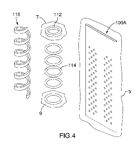
Another embodiment of the invention is shown in FIGS. 4-10 and will be seen to
include an alternate
sleeve 100A, a flat ring 112, a plurality of o-rings 114 and a length of foam
tape 116.
7
CA 03013499 2018-08-02
WO 2016/141479 PCT/CA2016/050255
This sleeve 100A differs from the sleeve of FIGS. 1 and 2 in that (i) the
sleeve has a length L of about 180
mm (ii) each group has a length M of about 138.5 mm, consists of about 46
apertures and is spaced from
the ends by distances N, P of about 13.25mmm and 28.25mmm, respectively.
Each o-ring 114 has a 1" ID and a fractional width of 1/8".
The flat ring 112 ring has an ID of 31.3mm, an OD of 44mm and a thickness of
6.35mm.
The foam tape 116 is 20" long, .25" wide and .125" thick and has an adhesive
back covered with a
release strip, not shown, which can be removed to expose the adhesive.
This structure functions in a generally similar manner to that of FIG. 1,2,
but is used to form a grip.
To form a grip as shown in FIG. 10, one:
= places the o-rings in spaced relation to one another upon the end of the
stick furthest the blade
= places the flat ring on the handle end
= places the sleeve over the o-rings and flat ring
= applies heat to the sleeve, to shrink the sleeve to a working size that
surrounds the portion in
close-fitting relation.
Again, the apertures, in combination with the relief provided by the rings,
provides a grippable surface,
this time for hand receipt.
The sleeve can be used with the spiral tape in place of the rings; to do so,
one merely removes the
release strip, spirals the foam around the stick and carries out the remainder
of the steps above. The
sleeve can also be used with neither the foam strip nor the o-rings.
Further variations on the above are also possible.
For example, a version of the sleeve for the blade of a hockey stick is shown
in FIG. 11 and 12. This
sleeve 1008 is identical in dimensions to that of FIGS. 1, 2 but is
constructed from polyolefin heat shrink
8
CA 03013499 2018-08-02
WO 2016/141479 PCT/CA2016/050255
material having a 2:1 shrink ratio, 1% laterally of the type sold under Part
No. MHSP-2-0-ILL by Techspan
Industries
Another version of the kit of FIG. 4 is shown in FIG. 13. The sleeve 100C of
this kit, shown in FIG. 14 and
15, differs in that the side walls have a height Q of about 63 mm, the groups
each have a length R of
129mm and a height S of about 14.5mm, the groups are spaced apart from one
another a distance T of
about 23.5mm and spaced from the ends distances V and W of about 11.25mm and
39.75mm,
respectively. This sleeve and kit are useful for forming the hand grip of a
junior stick.
Yet another version of the sleeve is shown in FIGS. 16 and 17. This sleeve
100D differs from that of FIGS
11 & 12 in that (i) the side walls have a height AA of about 120mm ; (ii) the
sleeve has a length CC of
about 405mm; and (iv) the groups each have a length DD of about 296 mm in
length, thereby rendering
the sleeve suitable for use on the blade of a goalie stick. This sleeve is
advantageously used with the
sleeve 100E of FIGS. 18-20, which is adapted to fit around the heel of a
goalie stick to provide
reinforcement. As the heel is not normally used for puck handling, this sleeve
lacks perforations.
Yet another version of the sleeve is shown in FIGS. 21-23. This sleeve 100F
differs from that of FIGS. 16-
17 in that (i) the sleeve has a length EE of about 305mm; (ii) the sleeve is
made of PVC heat shrink
material, with a2:1 shrink ratio, 10% lateral shrink; and (iii) there is only
a single grouping, with a length
FF of 251.5mm . This sleeve can also be used with the sleeve 100G of FIGS. 24-
26.
A yet further variation of the sleeve is shown in FIG. 27 and FIG. 28. The
sleeve 100G differs in that it
has a length FF of about 533mm, and is useful to form, in combination with
another washer and a foam
strip, a goalie stick top grip as shown in FIG. 30
Other variations are possible, as shown in FIGS. 31-84.
Further, whereas the specification makes reference to apertures of about 3.5mm
in diameter, it has
been found that apertures as small as 2.8mm have some utility.
For example, only, the invention could also be embodied for lacrosse sticks.
Accordingly, the invention
should be understood to be limited only by the accompanying claims,
purposively construed.
9