Note: Descriptions are shown in the official language in which they were submitted.
CA 03013543 2018-08-02
WO 2017/168232
PCT/IB2017/000316
"A SUCTION ROLLER STRUCTURE FOR AN INTERLEAVING MACHINE"
******
Technical Field of the Invention
The invention relates to a suction roller to pneumatically transport sheets of
paper,
especially the type of suction roller used in operating units intended for
cutting and/or
folding interfolded sheets of paper, i.e. stacked folded sheets, in such a way
as to
obtain a partial overlapping of the adjacent edges of the sheets. This kind of
arrangement is used, for example, to manufacture packs of stacked napkins in
such
a way that upon extracting the napkin in the extraction position, one edge of
the
underlying napkin is automatically lifted, in such a way as to ease the
extraction of
the following napkin.
This type of arrangement may be used for toilet paper, face tissues and more.
State of the Art
It is known that interfolders are equipped with a couple of juxtaposed and
counter-
.. rotating rollers, through which the sheets of paper to be folded/cut are
fed.
Depending on the task that must be performed, cutting blades or projections
may be
present on the surfaces of one of the rollers and, on the opposite roller,
there are
corresponding slots which rotate in line with the blades/projections so as to
have the
processed sheet of paper cut or folded.
Once folding is performed, the sheets of paper are moved to an underlying
device,
which is known as a "stacker", which forms numerical stacks of sheets and
works in
line with the rotation of rollers.
During the operations, rollers must also perform the task of keeping the
sheets
adhering to the external surface.
To this end, the rollers of the interfolding units are equipped with bores
connected to
a suction system, which can be laterally or centrally mounted with respect to
the
roller.
A central suction system is known from EP1457444, which envisages a central
vacuum source, comprising a fixed hollow cylinder, which through partial
suction
chambers is transferred to bores on the external surface of the rotating
suction roller,
so as to selectively activate the communication of the external bores
distributed on
the section of the cylinder that corresponds to the partial suction chamber,
with the
machine's suction system during the relative rotation of the two bodies.
The solution known from EP1457444 has some drawbacks though, since the
1
Attorney Ref.: 1163P0120A01
communication selection between the internal cylinder and the external bores
is
ensured by sliding seals that are in contact with the internal surface of the
suction
roller, and are thus worn out and drawn, and subjected to high friction since
the seals
are subject to high wear (and thus to regular maintenance), which is also due
to the
relatively high vacuum that must be created in order achieve the desired
suction effect
on the surface.
Moreover, this system, when applied to the folding rollers of interfolders,
needs them
to be fed by also using a side suction system, or else it is not possible to
switch
between the suction phase and the release phase of the sheets of paper in the
operation area of the rollers, according to the angular position of the
folding rollers.
Moreover, the system disclosed by EP1457444 is relatively rigid if the format
of the
transported sheets of paper must be changed, and thus the angular distance
between
the suction bores that are activated one after the other must be adjusted.
The need is thus felt for a suction roller, especially for interfolding units
for sheets of
paper, based on a reliable and efficient structure, and characterized by a
suction
system able to flexibly adjust to any possible change to the format of the
sheets of
paper.
Obiect of the Invention
The present invention is intended to provide a suction roller to be used with
interfolding
units, which allows to overcome the drawbacks of the already known solutions.
According to the invention, the object is achieved by using a suction roller
for
interfolding units according to the main claim.
Further technical objects and advantages are achieved by units according to
the
dependent claims.
Summary of the Invention
A first advantage is that the suction roller of the invention allows the
operator to select
the arrangement and succession of the external suction bores in a simple and
reliable
way.
A second advantage is that the suction system can be adapted if the format of
the
processed sheets of paper is changed.
In another aspect, this document discloses a suction roller structure to
pneumatically
transport sheets, the suction roller structure comprising: a suction source; a
rotating
external roller comprising longitudinal rows of bores angularly spaced and
said
longitudinal rows of bores selectively communicating with said suction source
during
2
Date Recue/Date Received 2022-02-28
Attorney Ref.: 1163P0120A01
angular rotation of said rotating external roller, said suction source
comprising an
internal cavity of an inner hollow cylinder and said rotating external roller
being
rotatable with respect to said inner hollow cylinder, said inner hollow
cylinder
comprising an arrangement of bores to establish a pneumatic communication
between
said internal cavity and a ring gap defined by an external surface of said
inner hollow
cylinder and an internal surface of said rotating external roller; a
distribution of
intermediate suction chambers communicating and associated with corresponding
longitudinal rows of bores; a distribution of pneumatic valves, each of said
pneumatic
valves being interposed between said suction source and one of said
intermediate
suction chambers; and an actuation means operatively associated with said
rotation
of said rotating external roller and arranged for opening one or more of said
pneumatic
valves at one or more angular positions taken by said rotating external
roller.
In another aspect, this document discloses an interfolding unit comprising: a
pair of
folding rollers arranged side by side and counter-rotating to operate at a
common
tangency point on successions of sheets fed according to a staggered position
between said pair of folding rollers, at least one of said folding rollers
comprising a
suction roller structure, said suction roller structure comprising a suction
source, a
rotating external roller, a distribution of intermediate suction chambers, a
distribution
of pneumatic valves and an actuation means, said rotating external roller
comprising
longitudinal rows of bores angularly spaced and said longitudinal rows of
bores
selectively communicating with said suction source during angular rotation of
said
rotating external roller, said distribution of intermediate suction chambers
communicating and being associated with corresponding longitudinal rows of
bores,
each of said pneumatic valves being interposed between said suction source and
one
of said intermediate suction chambers, said actuation means being operatively
associated with said rotation of said rotating external roller and arranged
for opening
one or more of said pneumatic valves at one or more angular positions taken by
said
rotating external roller, said suction source comprising an internal cavity of
an inner
hollow cylinder and said rotating external roller being rotatable with respect
to said
inner hollow cylinder, said inner hollow cylinder comprising an arrangement of
bores
to establish a pneumatic communication between said internal cavity and a ring
gap
defined by an external surface of said inner hollow cylinder and an internal
surface of
said rotating external roller.
2a
Date Recue/Date Received 2022-02-28
Attorney Ref.: 1163P0120A01
List of the Drawings
These and other advantages will be better understood by anyone skilled in the
art
thanks to the following specification and the accompanying drawings, given as
a
non-
2b
Date Recue/Date Received 2022-02-28
CA 03013543 2018-08-02
WO 2017/168232
PCT/IB2017/000316
limiting example, wherein:
- Fig. 1 schematically shows an axonometric view of a suction roller for an
interfolding unit according to the invention;
- Fig. 2 shows the roller of Fig. 1 in a longitudinal front view;
- Fig. 3 shows the roller of Fig. 1 in a side view;
- Fig. 4 shows the roller of Fig. 3 in a longitudinal C-C section;
- Fig. 5 shows the roller of Fig. 2 in a diagonal F-F section;
- Fig. 6 shows the roller of Fig. 2 in a diagonal A-A section and a detail D;
- Fig. 7 shows the detail pertaining to a valve used in the roller of the
invention;
- Fig. 8 shows the valve of Fig 7 in a B-B section;
- Fig. 9 shows an isometric view of a valve used in the roller of the
invention, a few
pieces of which have been removed for a better understanding;
- Fig. 10 shows a detail G of Fig. 8;
- Fig. 11 shows the internal hollow cylinder of the roller of Fig. 1 in a
longitudinal front
.. view;
- Fig. 12 shows the cylinder of Fig. 11 in a side view;
- Fig. 13 shows the cylinder of Fig. 11 in a top view;
- Fig. 14 shows a longitudinal suction chamber of the roller of Fig. 1 in a
longitudinal
front view;
- Fig.15 shows the detail G of Fig. 14;
- Fig. 16 shows the top view of the chamber of Fig. 14;
- Fig. 17 shows an isometric view of the chamber of Fig. 14;
- Fig. 18 schematically shows an interfolder equipped with suction rollers
according
to the invention;
- Fig. 19 shows a preferred embodiment of the longitudinal suction chamber of
the
roller of Fig. 1 in an isometric view;
- Fig. 20 shows the detail A of Fig. 19;
- Fig. 21 schematically shows two suction rollers while the interfolding unit
is running;
- Fig. 22 schematically shows the functioning of the machine in Fig. 21.
Detailed Description
With reference to the attached drawings, described herein is a preferred
embodiment
of a structure, according to the invention, of a suction roller for
pneumatically
transporting sheets, which is especially used in a U-shaped interfolding unit.
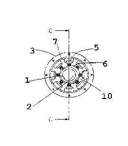
The structure comprises a hollow cylinder 1 equipped with an internal cavity
2, which
3
CA 03013543 2018-08-02
WO 2017/168232
PCT/IB2017/000316
is preferably fixedly mounted onto a pair of sides F so that the cavity 2 is
constantly
connected to a suction source V (Fig. 2).
Moreover, an external roller 3 is mounted onto cylinder 1, rotatable with
respect to
cylinder 1, for instance on side bearings 32, and is provided with
longitudinal rows of
bores 4 angularly spaced (for example eight equally spaced rows) and
selectively
communicating with said internal cavity 2 during the angular rotation of the
roller 3.
Preferably, the roller 3 is a folding roller of the type used in pairs in
interfolders to fold
successions of sheets 7a, 7b at a common tangency point Z, in order to create
stacks of interfolded sheets S (Fig. 18) in combination with detachment
elements M
that detach the sheet from the rollers.
To this end, the roller 3 may be equipped with an external grooved surface 22
that
transports the sheets and towards which the bores 4 are faced.
The functioning of an interfolder is generally known, for example from the
Italian
patent application B02008A000167 in the name of the same inventors and is thus
not described in further detail.
According to the invention, the structure of the roller comprises an
arrangement of
pneumatic valves 5 that are normally closed and inserted between the internal
cavity
2 of the hollow cylinder 1 and at least one bore 4 of the roller 3, preferably
a
longitudinal row of bores 4.
In order to achieve the selective communication of bores 4 with the vacuum
cavity 2,
cam means 6 are envisaged and operatively associated to rotation of the roller
3 and
arranged to be able to open one or more of said valves 5 at one or more
angular
positions taken by the roller 3.
In the described embodiment, the hollow cylinder 1 comprises an arrangement of
bores 9 to establish a pneumatic communication between the internal cavity 2
and a
ring gap 10 that is generally defined by the external surface 11 of the
internal cylinder
1 and the internal surface 12 of the roller 3 and towards which valves 5 are
faced,
normally closed.
Preferably, valves 5 comprise a shutter 13 that is normally closed, equipped
with a
sealing head 23 and a stem 24, interposed between a vacuum volume 14
communicating with the gap 10 and the bores 4 of the roller 3. Valves 5 are
also
equipped with an actuation element 8, for instance a small wheel connected to
the
stem 24, that can be activated by the cam means 6 against the thrust of an
elastic
return element 16 as a reaction to the rotation of the roller 3.
4
CA 03013543 2018-08-02
WO 2017/168232
PCT/IB2017/000316
In the described example, cam means 6 comprise at least an external ring
profile of
the hollow cylinder 1 arranged in correspondence to at least one actuation
element 8
of at least one valve 5.
What is understood, however, is that various embodiments of the cam means will
be
possible, as well as various technical solutions for actuating the valves 5.
In particular, cam means 6 may be fixed or adjustable (for example, by
providing cam
profiles that can be replaced or adjusted in an angular position with respect
to
cylinder 1) in order to be able to change the angular phase of the
opening/closing of
the valves 5.
.. With particular reference to Figures 14 to 20, the valves 5 are mounted
along at least
one longitudinal chamber 7 placed in the space of the gap 10 and secured by
means
of a pneumatic seal with respect to the internal surface of the roller 3 by at
least one
longitudinal row of bores 4.
Thanks to this solution, the chamber 7 is pneumatically isolated with respect
to the
gap 10 and the vacuum volume 14 constantly communicates with the gap 10 by
means of transverse bores 15 of the longitudinal chamber 7.
Particularly, the pneumatic seal of chamber 7 is obtained by seal-applying the
peripheral edges 24 of the chamber 7 to the internal surface 12 of the roller
and by
fixing the chamber 7 to the roller, for example by means of screws.
Preferably, moreover, the longitudinal chamber 7 is in the shape of a
longitudinal
profile made of linear modules or segments 17, alternating with valve-holding
blocks
18.
In this way, it is possible to compose chambers 7 of the correct length for
the roller 3,
to be put in suction, and to place the valves in the desired position.
Figures 19, 20 show a preferred embodiment of the chamber 7.
In this embodiment, the chamber 7 comprises one or more sealing buffers 25
that
can be placed at predetermined positions along the chamber 7 at the sides of
the
valves 5. In different embodiments, the buffers 25 may be securely positioned
by
means of screws or by means of adjusting means, such as a threaded rod 26 that
is
accessible and operable from the outside, at the ends of the chamber 7.
Advantageously, this solution allows to adjust, and possibly section into
several
sectors, the transverse width of the volume of the chamber that is subject to
the
suction phase, thus increasing the flexibility of the system for the transport
of sheets
of different transverse format, without having to plug the bores 4 and without
5
CA 03013543 2018-08-02
WO 2017/168232
PCT/IB2017/000316
reducing the efficiency and speed of the suction and release phases.
What is specified is that in a different embodiment, the chamber 7 can be
obtained
directly in the thickness of the roller 3 itself instead of being taken back.
With particular reference to Figure 21, the functioning of two folding rollers
according
to the invention is shown, upon the exchange of the sheet from a roller 3s
(shown on
the left in the representation) to the other roller 3d.
In order to achieve the exchange, the valves 5 of the roller 3s are closed and
do not
create vacuum in the bores 4, while the valves 5 of the roller 3d enters the
vacuum
state and hold the sheet.
In the figure, "a" indicates the angular position of the cams 6 of the roller
that hold the
valves 5 open, and thus in the vacuum state, such valves holding the head and
tail
edges of the sheets to be folded, and "b" indicates the angular position of
the cams 6
of the roller (indicated by a dotted line) that hold the valves open, such
valves holding
the central portion of the same sheets.
During the rotation of the suction rollers 3s, 3d, cams 6 in the "a" position
cause the
valves 5 to open at the point "t" of the exchange of the sheet between the
cutting
roller 31 - placed above (and only schematically shown in the figure) - and
the folding
roller 3s and let the valves close at the tangency point "z" between the left
and right
folding rollers 3s, 3d.
Cams corresponding to the angle "b" cause instead the valves to open at the
tangency point z and close them at the point S, where the sheet must be
detached
from the underlying detachment elements M.
As a result of the succession of the hold and release phases of the sheet and
of the
rotation of the folding roller, the cut sheet is then transported, folded by
the two
rollers at the tangency point "z" and then released at the bottom.
As it is known in the sector, in order to obtain interfolding, the succession
of the
suction and release states as described above keeps going in an alternatemay
in the
two rollers 3s, 3d in order to transport, fold and release the two successions
of
sheets fed to the two left and right rollers and staggered in the longitudinal
direction.
Figure 22 schematically shows phases fl 45 of interfolding of two successions
of
sheets 7a, 7b, performed with a pair of folding rollers 3s, 3d according to
the present
invention.
phase f1
= During this phase, a first fold P between the first and the second face
of a
6
CA 03013543 2018-08-02
WO 2017/168232
PCT/IB2017/000316
sheet 7a wrapped on the first roller 3s is created, the sheets 7a and 7b are
coupled starting from the tangency point Z;
= the valves 5 of the first roller 3s immediately upstream and downstream
of the
tangency point z are in suction and rotatively drag the tail edge of the first
face
and the second face of the sheet 7a,
= the valves 5 of the second roller 3d, immediately downstream of the
tangency
point, are closed,
= the element M of the second roller 3d has started the detachment of the
head
edge of the first face of sheet 7a,
1.0 phase f2
= the valves 5 of the first roller 3s, immediately downstream of the
tangency
point z, are still in suction mode and rotatively drag the second face of the
sheet 7a and the first face, coupled to it, of the second sheet 7b;
= the valves 5 of the second roller 3d, upstream of the tangency point, are
open
and drag the second sheet 7b;
= the element M of the second roller 3d has performed the detachment of the
head edge of the first face of sheet 7a;
phase 13
= during this phase, the succession of foldings of the interfolded (that is
partially
overlapped) sheets 7a, 7b begins,
= the valves 5 of the first roller 3s, immediately upstream of the tangency
point
z, are open and feed a sheet 7a towards the tangency point Z,
= the valves 5 of the first roller 3s, immediately downstream of the
tangency
point z, are closed, and they do not hold the coupled sheets 7a/7b;
= the valves 5 of the second roller 3d, upstream of the tangency point, are
open
and drag the second sheet 7b;
= the valves 5 of the second roller 3d, downstream of the tangency point,
are
open and drag the coupled sheets 7a/7b, thus forming a further fold P,
= the element M of the first roller 3s has started the detachment of the
coupled
sheets 7a/7b.
phase 14
= at this phase, the first interfolding of two staggered sheets 7a, 7b has
been
already obtained,
7
CA 03013543 2018-08-02
WO 2017/168232
PCT/IB2017/000316
= the valves 5 of the first roller 3s immediately upstream of the tangency
point z
are open and drag a sheet 7a to the tangency point Z,
= the valves 5 of the first roller 3s, immediately downstream of the
tangency
point z, are closed, and they do not hold the coupled sheets 7a/7b;
= the valves 5 of the second roller 3d, upstream of the tangency point, are
open
and drag the second sheet 7b;
= the valves 5 of the second roller 3d, downstream of the tangency point,
are
open and drag the coupled sheets 7a/7b, thus completing the further fold P,
= the element M of the first roller 3s has completed the detachment of the
coupled sheets 7a/7b;
= the element M of the second roller 3d is about to start the detachment of
the
coupled sheets 7a/7b upstream of the further fold p;
phase f5
= in this phase, the second interfolding of two staggered sheets 7a, 7b has
been
obtained,
= the valves 5 of the first roller 3s immediately upstream of the tangency
point z
are open and drag a sheet 7a to the tangency point Z,
= the valves 5 of the first roller 3s, immediately downstream of the
tangency
point z, are open and drag the coupled sheets 7a/7b, starting to form another
further fold P;
= the valves 5 of the second roller 3d upstream of the tangency point are
open
and drag the second sheet 7b towards the tangency point;
= the valves 5 of the second roller 3d, downstream of the tangency point,
are
closed, and do not hold the coupled sheets 7a/7b,
= the element M of the second roller 3d has started the detachment of the
coupled sheets 7a/7b upstream of the fold P that had been previously created.
The described phases are repeated in succession and the interfolded sheets
7a/7b
are stacked at the bottom, forming a stack of interfolded sheets.
The invention presents important advantages in that the provided seals are
tight,
there is no drawing or dragging, friction is low and allows energy saving and
reduced
pollution, and furthermore, they can independently enter the suction mode and,
when
valves are activated, the vacuum does not affect the friction inside the
roller.
A further advantageous aspect is that a single suction system feeds all the
rollers of
8
CA 03013543 2018-08-02
WO 2017/168232
PCT/IB2017/000316
the interfolder.
A further advantageous aspect is that the valves may change in number, but
they are
all the same regardless of the number of sheets to be processed.
A further advantageous aspect is that the roller can be equipped with
different
sectors, and each sector can be provided with an internal buffer, which may
have
different positions with respect to the valves and can thus close selected
bores by
reducing the suction chamber.
A further advantageous aspect is that the shutter valves are long-lived over
the years
and they can be changed without disassembling the roller.
A further advantageous aspect is that the adjustment of the transport and
transfer
suction of sheets is made easier, with the possibility of installing an
automatic suction
variation system, that might be advanced or delayed.
The present invention has been described according to preferred embodiments,
but
equivalent variants can be designed without departing from the agreed scope of
protection.
9