Note: Descriptions are shown in the official language in which they were submitted.
CA 03013674 2018-08-03
WO 2017/143450
PCT/CA2017/050239
Method and Apparatus for Centrifugal Concentration Using Vibratory
Surfaces and Rotor Bowl for Use Therein
Reference to Related Applications
[0001] The present application claims the benefits, under 35 U.S.C. 119(e), of
U.S.
Provisional Application Serial No. 62/299,645 filed February 25, 2016 entitled
"Method
and Apparatus for Centrifugal Concentration Using Vibratory Surfaces" which is
incorporated herein by this reference.
Technical Field
[0002] The present invention relates to centrifugal concentrators of the
rotating bowl type
for the separation and recovery of particulate solids of higher specific
gravity, such as
gold, from a slurry containing such particulate solids as well as particulate
solids of a
lower specific gravity and liquid.
Background
[0003] The problem of separating particles of high density such as precious
metals from
tailings and other slurry streams has attracted a great many attempted
solutions. The
problem is that of separating small particles of higher density from a slurry
containing
water and particles of lower density such as sand. One approach has been to
use the
centrifugal force created in a rotating bowl to separate the high density
particles from the
lower density slurry. One method of using a rotating bowl for this purpose
involved
placing obstructions such as ribs in the path of the rotating slurry to trap
the heavier
particles. However where the slurry contains fine, dense particles such as
magnetite, the
grooves or depressions designed to retain the concentrate rapidly pack with
the unwanted
fine particles.
[0004] The problem of packing has been addressed by the centrifugal
concentrator which
is the subject of U.S. Patent no. 4,824,431 (McAlister) which is incorporated
herein by this
1
CA 03013674 2018-08-03
WO 2017/143450
PCT/CA2017/050239
reference. In that centrifugal concentrator, there are no obstacles to the
flow of the slurry
in the rotating drum. The slurry is delivered to the vicinity of the bottom of
the rotating
drum and travels up the smooth interior surface of the drum. The interior
surface has three
continuous zones: an outwardly inclined migration zone, a generally vertical
retention
zone above the migration zone, and an inwardly-inclined lip zone above the
retention
zone. The respective lengths and inclinations of the zones are selected to
produce flow
conditions in which less dense particles are expelled from the drum while
denser particles
migrate to and are retained in the retention zone. The result is that an
enriched layer of
concentrate accumulates in the retention zone without the use of ridges or
grooves which
may become packed.
[0005] A second approach to the packing problem in centrifugal concentrators
is that
disclosed in Australian Patent no. 22,055/35 (MacNicol), complete
specification published
23 April, 1936. Figure 1 of that patent discloses a centrifugal concentrator
in which the
entire inner wall of the rotating bowl is provided with a plurality of annular
riffles and a
plurality of orifices arranged at the deepest point between the riffles. Water
under pressure
is supplied to the orifices through a supply and pressure jacket around the
bowl. The flow
of liquid through the orifices causes the particles caught in the riffles to
be agitated and
allows the heavier particles to penetrate to the wall of the bowl.
[0006] The present applicant has also disclosed in CA2149978, which is
incorporated
herein by this reference, a concentrator which combines features of the
MacNicol and
McAlister types for separating particulate material of higher specific gravity
from a liquid
slurry comprising a liquid and particulate material of different specific
gravities. It has a
capture zone which is fluidized from a source of liquid under pressure located
radially
outwardly of the capture zone. Centrifugal concentrators of the fluidizing bed
approach of
Australian Patent no. 22,055/35 have a number of disadvantages. Since a large
volume of
water is required to supply the water jacket to fluidize the wall of the bowl,
concentrators
of this type consume a good deal of water. The added water consumption adds to
the cost
of operation and disposal of the waste slurry output, and in some cases such
as grinding
circuits can have a negative impact on the overall system. Due to the addition
of the
fluidizing water to the input slurry, the capacity of the bowl to process the
input slurry is
reduced, and more energy is required to rotate the added water required for
the
2
CA 03013674 2018-08-03
WO 2017/143450
PCT/CA2017/050239
fluidization. The addition of internal ridges also adds to the concentrator
weight. There is
therefore a need for a centrifugal concentrator which has the advantages of
both the
McAlister and MacNicol-type centrifugal concentrators, but which does not use
water and
requires less energy to operate than the MacNicol-type concentrator.
[0007] The foregoing examples of the related art and limitations related
thereto are
intended to be illustrative and not exclusive. Other limitations of the
related art will
become apparent to those of skill in the art upon a reading of the
specification and a study
of the drawings.
Summary
[0008] The following embodiments and aspects thereof are described and
illustrated in
conjunction with systems, tools and methods which are meant to be exemplary
and
illustrative, not limiting in scope. In various embodiments, one or more of
the above-
described problems have been reduced or eliminated, while other embodiments
are
directed to other improvements.
[0009] There is provided therefore according to one embodiment, a rotor bowl
for use in a
centrifugal concentrator for separating particulate material of higher
specific gravity from
a liquid slurry comprising a liquid and particulate material of different
specific gravities,
the rotor bowl comprising an open end, a substantially closed end and an inner
surface;
wherein the inner surface of the rotor bowl comprises an outwardly inclined
migration
surface and a capture zone above the migration surface, wherein the capture
zone
comprises a generally vertical annular wall located radially outwardly of the
migration
zone, and the generally vertical annular wall comprises a vibratory surface
adapted to be
selectively vibrated to thereby stratify particulate material or slurry
located in contact with
or adjacent to the vibratory surface within the capture zone to thereby permit
the heavier
concentrate to accumulate in the area closest to the wall of the capture zone.
The vibratory
surface may be the continuous inner liner of the capture zone, or separate
vibrating
surfaces may be provided on the surface of the inner liner in the capture
zone. The
vibratory motion may be provided by one or more vibrators mounted radially
outwardly of
each vibratory surface. The rotor bowl may also comprise a plurality of
springs mounted
3
CA 03013674 2018-08-03
WO 2017/143450
PCT/CA2017/050239
on the outer periphery of the vibrators and which are each biased to bear
against the outer
surface of a vibrator to offset centrifugal force so that each vibrator is
kept in contact with
the vibrating surface during rotation of the hollow bowl.
[0010] According to further embodiments, a centrifugal concentrator
incorporating the
foregoing rotor bowl is provided and a method of using same.
[0011] In addition to the exemplary aspects and embodiments described above,
further
aspects and embodiments will become apparent by reference to the drawings and
by study
of the following detailed descriptions.
Brief Description of the Drawings
[0012] Exemplary embodiments are illustrated in referenced figures of the
drawings. It is
intended that the embodiments and figures disclosed herein are to be
considered
illustrative rather than restrictive.
[0013] Fig. 1 is a perspective view of the prior art concentrator as disclosed
in CA
2149978.
[0014] Fig. 2 is a cross-section of the prior art concentrator of Fig. 1 taken
along lines 4-4
with the drive assembly removed and the flushing manifold slightly
repositioned for ease
of illustration.
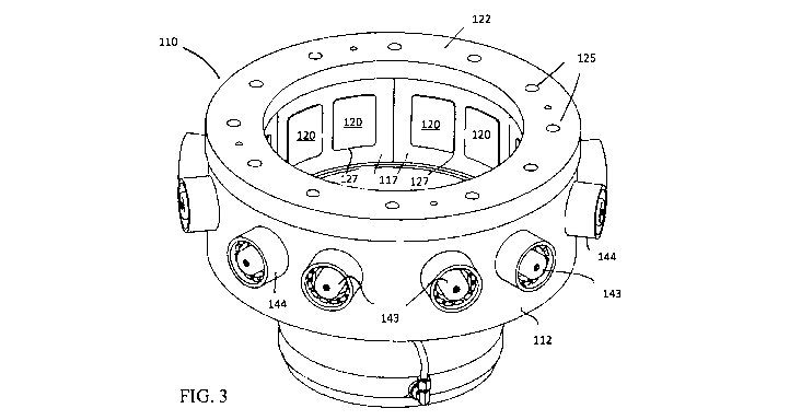
[0015] Fig. 3 is a perspective view of an embodiment of the vibrating rotor
bowl
assembly for the centrifuge of the invention.
[0016] Fig. 4 is a top view of the rotor bowl assembly shown in Fig. 3.
[0017] Fig. 5 is a cross-section view taken along lines A-A of Fig. 4.
[0018] Fig. 6 is a cross-section view of a second embodiment of the vibrating
rotor bowl
assembly for the centrifugal concentrator of the invention lines taken along
lines A-A of
Fig. 15.
[0019] Fig. 7 is a cross-section view of the vibrating rotor bowl assembly for
the
embodiment of the invention shown in Fig. 6, taken along lines B-B of Fig. 15.
4
CA 03013674 2018-08-03
WO 2017/143450
PCT/CA2017/050239
[0020] Fig. 8 is an isometric view of the vibrating rotor bowl assembly shown
in Fig. 6.
[0021] Fig. 9 is an isometric view of the vibrating rotor bowl assembly for
the centrifugal
concentrator of the invention as shown in Figure 8, with the casing in phantom
outline for
ease of illustration.
[0022] Fig. 10 is a cross-section taken along lines 10-10 of Fig. 9.
[0023] Fig. 11 is an isometric view of the vibrating rotor bowl assembly for
the centrifuge
of the invention as shown in Figure 8 with the casing removed.
[0024] Fig. 12 is a cross-section taken along lines 10-10 of Fig. 9
illustrating the capture
of target particles from the slurry.
[0025] Fig. 13 is a cross-sectional detail of a vibrator-to-vibrating plate
connection as
shown in Fig. 12 and illustrating a bed of captured target particles from the
slurry.
[0026] Fig. 14 is an exploded perspective view of the vibrating rotor bowl
assembly for
the embodiment of the invention shown in Fig. 6.
[0027] Fig. 15 is a top view of the rotor bowl assembly shown in Fig. 14.
Description
[0028] Throughout the following description specific details are set forth in
order to
provide a more thorough understanding to persons skilled in the art. However,
well
known elements may not have been shown or described in detail to avoid
unnecessarily
obscuring the disclosure. Accordingly, the description and drawings are to be
regarded in
an illustrative, rather than a restrictive, sense.
[0029] The term "stratify" is used herein to mean the act of sorting the
target particulate
material by specific gravity or density in the capture zone described below,
in the radial
direction due to centrifugal force from rotation of the rotor. Such
stratification may be
achieved as described below all or in part by transmission of vibration or
shaking to
relatively free-flowing particles in the capture zone of the rotor which are
already in the
nature of a bed, or are closer to a slurry in nature. Or it may be achieved by
the application
of vibratory forces or shaking in combination with fluidization using fluid or
gas injection,
5
CA 03013674 2018-08-03
WO 2017/143450
PCT/CA2017/050239
or in the case of a solidified bed in the capture zone of the rotor by using
more intense
vibration to cause liquefaction.
[0030] A prior art centrifugal concentrator as disclosed in CA2149978 is shown
in Fig. 1
and 2. It has a frame 3, a shroud 4 consisting of shroud lid 5 and tailings
launder 14, and
drive motor 9. The frame is constructed of hollow steel sections which are
sealed to
provide water storage. The shroud lid 5 has openings for a slurry feed pipe 18
and
inspection ports 17 sealed by removable plugs, and an inner lining 6 of a wear
resistant
material such as LINATEXTm or a natural rubber. The flange of shroud lid 5 is
bolted to
the upper flange of tailings launder 14. Tailings launder 14 is provided with
a tailings
discharge port. A concentrate launder 16 with a concentrate discharge port is
also
provided. The floor of launder 14 is sloped downwardly to assist in a smooth
outward flow
of the discharge. Rotor 21 is formed of rotor bowl 23 and hollow rotor shaft
24. The rotor
21 is mounted for rotation in the frame 3 by bearing assemblies 25. The inner
surface of
rotor bowl 23 forms a migration zone A and a capture zone B, which cause the
denser,
target particles from the slurry flow to be concentrated in the capture zone
B. The rotor
shaft 24 is driven by a belt, located in belt guard 7 and driven by electric
motor 9. An
impeller 34 is provided on the center of baffle 36, which is raised above and
secured to the
floor of bowl 23. Impeller 34 has a plurality of upstanding vanes 31 to assist
in the
rotation of the slurry.
[0031] An external pipe 26 provides water under pressure from the frame 3 to a
hollow
flushing manifold 28 secured to feed pipe 18 and provided with holes 29. A
plumbing
assembly supplies water under pressure to a rotating union 37 through which
the water
passes to the hollow interior 35 of rotor shaft 24 from where it passes into
radially
extending passages 41 and thence into supply hoses 42 which carry the water
under
pressure to annular chamber 46. Rotor bowl 23 is formed of a lower bowl
section which is
bolted by bolts 61 to the upper sloping bowl section. Rotor bowl 23 has four
concentrate
outlets 64. The inner surface of bowl 23 and the upper surface of baffle 36
have a lining 63
of a wear resistant material such as LINATEXTm or a natural rubber. Rotor bowl
23 is
fixed to rotor shaft 24. The vertical wall of capture zone B has a plurality
of holes 48
formed therethrough in the areas between ribs 45. Holes 48 communicate with
hollow
chamber 46 which in turn is supplied with water under pressure through the
supply hoses
6
CA 03013674 2018-08-03
WO 2017/143450
PCT/CA2017/050239
42. The tops of the ribs follow generally the slope of the migration zone A if
it were
extended. Water is supplied to frame 3 through pipe 70, via water filter 72
having
pressure gauges 74. External release valve 76 permits water to be released to
clean filter
72. Pipe 71, with pressure gauge 82, supplies water from frame 3 to rotating
union 37. A
manual lever and valve permits bypass pipe 79 to be manually shut.
[0032] In operation, motor 9 is activated to rotate the rotor shaft 24. The
slurry feed is
introduced to the spinning rotor through feed pipe 18. Centrifugal forces
cause the slurry
to climb up the migration zone A on inner surface 63 of the rotor bowl section
past capture
zone B before being expelled into tailings launder 14 and thence out of the
machine
through a discharge port. The areas between the ribs 45 in capture area B are
initially
empty prior to introduction of the slurry. They rapidly fill with solids as
the slurry is
introduced. As the process advances, the heavier particles accumulate in these
areas. The
flow of water under pressure through the holes 48 from chamber 46 causes the
particles to
be agitated and permits the heavier concentrate to accumulate in the area
closest to the
wall of capture zone B. Once there has been a sufficient accumulation of
concentrate, the
feed slurry is shut off, the rotation of the bowl slows to a very gradual
rotation, water is
sprayed out through manifold 28 and the concentrate flows around baffle 36,
out outlets 64
into concentrate launder 16 from where it is collected. In order to avoid fine
slurry
particles penetrating into chamber 46 through holes 48, which would
necessitate cleaning
of chamber 46, and to assist in emptying the rotor of concentrate when the
rotor is slowly
rotating in the rinse cycle, water is constantly supplied into chamber 46
under pressure,
even during the rinse cycle.
[0033] The present improvement, shown in Fig. 3-15, provides a rotor bowl
assembly for
the concentrator described above which replaces the need for fluidizing water
with
vibrating surfaces. A first embodiment of rotor bowl 110 is illustrated in
Fig. 3-5 shown in
isolation for purposes of illustration, with outer support ring 112 in place.
Rotor bowl 110
has a sloped lower bowl section 114 with liner 116, forming the migration zone
A.
Capture zone B has a vertical wall 118, the radially inward surface of which
is formed of a
lining 117 of a wear resistant material such as rubber in which are provided a
plurality of
vibrating plates 120. Discharge lip ring 122 is secured to bowl 110 by a
plurality of
screws or nuts 129 (Fig. 14) threaded into an array of holes or slots 125, or
other securing
7
CA 03013674 2018-08-03
WO 2017/143450
PCT/CA2017/050239
means thereby forming the upper edge 123 of the capture zone B. The lower edge
121 of
capture zone B is formed by the upper edge of sloped lower bowl section 114
and liner
116.
[0034] Vibrating plates 120 are preferably steel plates. The radially inner
surfaces of
vibrating plates 120 are preferably smooth steel. The plates 120 are attached
to the lining
117 to form a continuous inner surface but plates 120 may move radially in
relation to the
lining 117. They may be glued to the liner by an appropriate adhesive along
the outer
surface of their outer edges 127. In the embodiment shown in Fig. 3-5, the
vibrating plates
120 sit on top of lining 117 to directly contact the slurry in the interior of
the rotor bowl.
Contacting the rear surface of each plate 120 is a vibrator 130 which extend
through
openings in lining 117. These are preferably pneumatic turbine vibrators.
Compressed air
is provided to each vibrator by pneumatic lines 132 (Fig. 11). Alternatively
they may be
hydraulically or piezo-electrically powered. The frequency and magnitude of
vibration is
selected based on the size and density of particles in the slurry and the
viscosity of the
slurry and can range from low frequency to ultrasonic. The direction of the
plane of
vibration of each vibrator may also varied from horizontal (radial), to
vertical or to some
other intermediate angle or orbital.
[0035] In the embodiment shown in Fig. 3-5, springs 142 are mounted within
spring
vibrator supports 143, housed within cylinders 144 on the outer periphery of
the vibrators
130 and which bear against the outer surface of the vibrators 130 to offset
centrifugal force
so that the vibrators are kept in contact with the vibrating plates 120 during
the high speed
rotation of the rotor 110.
[0036] In the embodiment shown in Fig. 6-15, specifically with reference to
the
embodiment shown in Fig. 6 and Fig. 13, lining 117 forms a continuous rubber
surface in
the capture zone B which is in contact with the slurry. The vibrating plates
120 contact or
are glued to the radially outer surface of lining 117. Each vibrator 130 is
bolted directly to
the rear of the associated vibrating plate 120 by bolts 133. In this
embodiment, vibrators
130 directly activate vibrating plates 120 and do not extend through the
lining 117 and do
not contact the slurry in the interior of the rotor bowl. The vibrators 130
extend through
openings 137 in outer ring 138 (Fig. 14). Outer ring 138 is fixed to rotor
bowl 114 at its
8
CA 03013674 2018-08-03
WO 2017/143450
PCT/CA2017/050239
upper and lower edges by bolts to rings 141, 143 (Fig. 13). The springs 135
support the
vibrating plates 120, vibrators 130 and interior rubber surface of lining 117
so that the
entire assembly has minimal deflection under centrifugal force during
operation. Springs
135 extend through holes 139 in outer ring 138 (Fig. 14). The springs 135 are
each
supported at their radially inner end by a post 131 on the vibrating plate
120. The radially
outer end of each spring 135 is preloaded by a bolt 136 threaded into hole 139
from the
outside of the outer ring 138. Casing 140 protects the vibrators from the
environment of
the concentrator.
[0037] In operation, the turbine vibrators are turned on prior to commencing
rotation of
the rotor bowl 110. Rotation of the bowl 110 is then commenced and the slurry
is
introduced to the interior of the bowl in the usual way. The depth of the lip
ring 122 is
adjusted in advance by selection of the inner radius of the lip ring 122 to
determine the
depth of the target bed 156 shown in Fig. 12 and 13. The vibration of the
vibratory plates
120 vibrates the particulate slurry in the vicinity of capture zone B to
permit the heavier
particles of concentrate to accumulate in the area 156 closest to the wall of
capture zone B
while lighter slurry 158 is expelled over intermediate bed 157. Once there has
been a
sufficient accumulation of target concentrate in bed 156, the feed slurry is
shut off, the
rotation of the bowl slows to a very gradual rotation, water is sprayed from a
rinse
manifold into the capture zone B to remove the target concentrate and the
recovered
concentrate then flows around the baffle 150, out outlets 152 (Fig. 10), into
a concentrate
launder from where it is collected.
[0038] As noted above, control means may be provided to vary the frequency and
magnitude of vibration, which is selected based on the size and density of
particles in the
slurry and the viscosity of the slurry and can range from low frequency to
ultrasonic.
Where the slurry is highly viscous and/or the particle bed in the capture zone
approaches
the properties of a solid with resistance to flow, a high frequency and/or
magnitude of
vibration may be required to liquefy the particle bed, or there may be
auxiliary fluidization
of the particle bed using injected fluid or gas. Control means in combination
with electric
servo motors may also be provided to vary the orientation of the vibratory
motors to vary
the direction of vibration from horizontal (radial), to vertical or some other
angle, or
orbital.
9
CA 03013674 2018-08-03
WO 2017/143450
PCT/CA2017/050239
[0039] While a number of exemplary aspects and embodiments have been discussed
above, those of skill in the art will recognize certain modifications,
permutations, additions
and sub-combinations thereof. It is therefore intended that the invention be
interpreted to
include all such modifications, permutations, additions and sub-combinations
as are
consistent with the broadest interpretation of the specification as a whole.