Note: Descriptions are shown in the official language in which they were submitted.
CONCRETE ANCHOR BODIES AND PLUGS
RELATED APPLICATION
This is-a nonprovisional application of provisional
application Serial No. 62/294,231, filed 02/11/2016.
FIELD OF THE INVENTION
The present invention is generally directed to an anchor
embedded in a concrete structure for transferring load to the
concrete structure, and particularly to placing the anchor
within the concrete structure and be accessible for connection
to a load.
SUMMARY OF THE INVENTION
The present invention provides an anchor for being embedded
in concrete for attachment to a fastener to support a load,
comprising a plug having a main body portion extending upwardly
from a base portion, the plug for being attached to a form board
prior to pouring of concrete, the plug having an end portion
disposed a distance from the form board; and an anchor body
attached to the end portion. The plug is separable from the
anchor body and removable from the concrete after the concrete
-1-
CA 3014187 2020-04-06
GA 03014187 2018-08-09
WO 2017/139612 PCT/US2017/017419
is cured, leaving the anchor body embedded in the concrete, the
plug providing a void in the concrete after removal to provide
an access opening for a threaded portion of a fastener to attach
to the anchor body.
The present invention also provides a plug for forming
threads in concrete for attachment to a fastener to support a
load, the plug for attachment to a form board prior to pouring
of concrete, the plug including an end portion disposed a
distance from the form board. The end portion is threaded for
molding threads in the concrete. The plug is removable from the
concrete after the concrete is cured, leaving a mold of the
threads in the concrete, the plug providing a void in the
concrete after removal from the concrete to provide an access
opening for a threaded portion of a fastener to attach to the
threads molded in the concrete.
The present invention further provides an anchor for being
embedded in concrete for attachment to a fastener to support a
load, comprising a plug having a main body and a base attached
to the main body, the base for attachment to a form board prior
to pouring of concrete, the main body including an end portion
disposed a distance from the form board; an anchor body attached
to the end portion; the main body including an opening extending
-2-
CA 03014187 2018-08-09
WO 2017/139612 PCT/US2017/017419
from the base to the end portion, the opening providing an
access opening for a threaded portion of a fastener to attach to
the anchor body embedded in the concrete after the base is
removed after the concrete has cured.
A plug for forming an impression in concrete for attachment
to a fastener to support a load, the plug for attachment to a
form board prior to pouring of concrete, the plug including an
end portion disposed a distance from the form board; the end
portion including a first circumferential groove and a removable
ring partly disposed in the groove, the ring for molding a
circular groove in the concrete. The plug is removable from the
concrete after the concrete is cured, leaving a mold of the ring
in the concrete, the plug providing a void in the concrete after
removal to provide an access opening for a cylindrical body with
a second circumferential groove with a locking ring to attach to
the first circumferential groove in the concrete, the
cylindrical body being attached to a fastener for securing a
load.
BRIEF DESCRIPTION OF THE DRAWINGS
Fig. 1 shows a cross-sectional view of an anchor body with
tapered threads embodying the present invention.
-3-
CA 03014187 2018-08-09
WO 2017/139612 PCT/US2017/017419
Fig. 2 shows a cross-sectional view of an anchor body with
straight threads embodying the present invention.
Fig. 3 shows a cross-sectional view of another anchor body
embodying the present invention.
Fig. 4 shows a cross-sectional view of yet another anchor
body embodying the present invention.
Figs. 5A-5D show finite element analysis of the anchor body
shown in Fig. 2.
Fig. 6A is a perspective view of an anchor body shown in
Fig. 2 attached to a plug embodying the present invention.
Fig. 6B is a perspective cross-sectional view of Fig. 6A
after the plug is removed from the concrete and showing a
threaded rod attached to the anchor body for supporting a load.
Fig. 6C is a perspective cross-sectional view of the anchor
body of Fig. 2 attached to the plug of Fig. 6A without the plug
extending past the top of the anchor body.
Fig. 6D is a perspective cross-sectional view of Fig. 60
after the plug is removed from the concrete and showing a
threaded rod attached to the anchor body for supporting a load.
-4-
CA 03014187 2018-08-09
WO 2017/139612 PCT/US2017/017419
Fig. 7 is a perspective cross-sectional view of a plug
attached to another anchor body made of a nut integrated with a
flange or washer.
Fig. 8A is a perspective view of the plug shown in Fig. 7
attached to a nut used as an anchor body.
Fig. 8B is a perspective view of the plug of Fig. 8A
embedded in concrete, showing a breakout cone generated by the
nut attached to an anchor rod supporting a load below.
Fig. 9 is a perspective cross-sectional view of another
plug attached to a nut used as an anchor body.
Fig. 10 is a perspective cross-sectional view of another
embodiment of a plug attached to a Nylon locknut used as an
anchor body.
Fig. 11 is a perspective cross-sectional view of the plug
shown in Fig. 7 attached to split nut used an anchor body.
Fig. 12 is perspective cross-sectional view of another
embodiment of a plug attached to a split nut having multiple
size threaded bores.
Fig. 13A is a perspective cross-sectional view of a plug
attached to a split nut used as an anchor body.
Fig. 13B is a perspective cross-sectional view of Fig. 13A
showing the plug removed from the concrete.
-5-
CA 03014187 2018-08-09
WO 2017/139612 PCT/US2017/017419
Fig. 130 is a perspective cross-sectional view of Fig. 13B
showing a threaded rod attached to the split nut.
Fig. 14A is a perspective cross-sectional view of the plug
of Fig. 11 attached to another embodiment of a split nut used as
an anchor body.
Fig. 14B is a perspective cross-sectional view of the plug
of Fig. 14A attached to another embodiment of a split nut used
as an anchor body.
Fig. 140 is a perspective cross-sectional view of another
embodiment of a plug attached to another embodiment of a split
nut used as an anchor body.
Fig. 15 is a perspective cross-sectional view of the plug
of Fig. 11 attached to a nut and a washer, both cooperating as
an anchor body.
Fig. 16 is a perspective view of another embodiment of a
plug attached to a nut and a washer, both shown in perspective
cross-section, both cooperating as an anchor body.
Fig. 17 is a perspective view of the plug of Fig. 11
attached to a nut and a metal bracket, both cooperating as an
anchor body.
Fig. 18 is a perspective cross-sectional view of a plug
shown in Fig. 17 attached to a nut and a round metal bracket.
-6-
CA 03014187 2018-08-09
WO 2017/139612 PCT/US2017/017419
Fig. 19 is a perspective view of the plug of Fig. 18
attached to a nut and a circular stud rail assembly.
Fig. 20 is a perspective view of the plug of Fig. 18
attached to a nut and a fixture holding a plurality of double
anchor studs.
Figs. 21A-210 show several shear cones (breakout cones)
generated by the nut and the double anchor studs shown in Fig.
20 when subjected to a downward load connected to the nut.
Fig. 22 is a perspective view of the plug of Fig. 18
attached to a nut and a circular metal hollow cylinder.
Fig. 23 is a perspective cross-sectional view of a plug
attached to a plurality of nuts with different size threaded
openings.
Fig. 24A is a perspective view of a plug attached to a
plurality of metal plates with formed threaded openings of
different sizes.
Fig. 24B is a perspective cross-sectional view of Fig. 24A
after the plug is removed from the concrete.
Fig. 25 is a perspective view of a plug similar to Fig. 7
or Fig. 9 showing its base portion attached to a form board.
Fig. 26 is a perspective cross-sectional view of a plug
attached to a metal formwork with a magnet and attached to a
-7-
CA 03014187 2018-08-09
WO 2017/139612
PCT/US2017/017419
plurality of formed anchor bodies with different size threaded
openings.
Fig. 27 is a perspective view of a plurality of plugs
attached to a metal plate with formed threaded openings.
Fig. 28 is a perspective view of a plug similar to the plug
shown in Fig. 23 but made of metal.
Fig. 29 is perspective cross-sectional view of a metallic
plug with an integrated fastener for attaching to a form board.
Fig. 30 is a perspective cross-sectional view of the plug
of Fig. 15 with its main body portion covered with a tapered
sleeve.
Fig. 31A is a perspective cross-sectional view in concrete
of Fig. 30 after the plug is removed from the concrete, with the
sleeve remaining in the concrete.
Fig. 31B is a perspective cross-sectional view in concrete
of Fig. 30 after the plug and the sleeve are removed from the
concrete.
Fig. 32 is a perspective cross-sectional view of a plug
with a cylindrical main body portion covered with a sleeve.
Fig. 33 is a perspective view of a plug with its main body
portion covered in a continuous sleeve.
-8-
CA 03014187 2018-08-09
WO 2017/139612 PCT/US2017/017419
Fig. 34 is a perspective view of a plug with a cylindrical
main body portion covered with a sleeve with overlapped end
portions.
Fig. 35 is a perspective cross-sectional view of a plug
attached to a wire coil or spring.
Fig. 36 is a perspective cross-sectional view of Fig. 35
after the plug is removed from the concrete, leaving the coil or
spring in the concrete.
Fig. 37A is a perspective cross-sectional view of a plug
with a portion without threads attached to a wire coil or
spring.
Fig. 37B is perspective cross-sectional view of Fig. 37A
after the plug is removed from the concrete and a threaded rod
attached to the wire coil or spring in the concrete for
supporting a load.
Fig. 38 is a perspective view of a plug attached to a
washer and a coil or spring.
Fig. 39 is a perspective cross-sectional view of a plug
attached to a coil or spring with multiple diameters.
Fig. 40 is a perspective cross-sectional view of Fig. 39,
showing the plug removed from the concrete and a threaded rod
-9-
CA 03014187 2018-08-09
WO 2017/139612 PCT/US2017/017419
attached to a lower portion of the coil or spring with a larger
diameter.
Fig. 41 is a perspective cross-sectional view of Fig. 39,
showing the plug removed from the concrete and a threaded rod
attached to an upper portion of the coil or spring with a
smaller diameter.
Fig. 42A is a perspective view of a plug attached to a coil
or spring made of shaped metal (not round).
Fig. 42B is a perspective cross-sectional view of Fig. 42A,
showing the plug removed, leaving the coil or spring in the
concrete.
Fig. 420 is a perspective cross-sectional view of Fig. 42B,
showing a threaded rod attached to the coil or spring for
supporting a load.
Fig. 43 is a perspective view of a plug attached to a coil
or spring of shaped metal (not round), showing the individual
coils touching the adjacent coil to seal the interior of the
coil or spring from the concrete.
Fig. 44A is a perspective view of a plug attached to a Heli
coil.
Fig. 44B is a perspective cross-sectional view of Fig. 44A.
-10-
CA 03014187 2018-08-09
WO 2017/139612 PCT/US2017/017419
Fig. 45 is a perspective view of a plug attached to a thin
wall formed metal in the shape of interior and exterior threads.
Fig. 46 is a perspective view of a non-continuous thin wall
formed metal in the shape of interior and exterior threads.
Fig. 47 is a perspective cross-sectional view of Figs. 45
and 46.
Fig. 48 is a perspective cross-sectional view of Figs. 45
and 46, showing the plug removed from the concrete, leaving the
formed metal in the concrete.
Figs. 49A and 49B are perspective cross-sectional views of
Fig. 45 with a closed top thin wall formed metal in the shape of
interior and exterior threads.
Fig. 50 is a perspective cross-sectional view of Figs. 49A
and 49B, showing the plug removed from the concrete.
Fig. 51 is a perspective cross-sectional view of Fig. 48
with a tapered thin wall formed metal in the shape of interior
and exterior threads.
Fig. 52 is a perspective cross-sectional view of Fig. 51,
showing a threaded rod attached to the formed metal for
supporting a load.
Fig. 53 is a perspective cross-sectional view of a plug.
-11-
CA 03014187 2018-08-09
WO 2017/139612 PCT/US2017/017419
Fig. 54 is a perspective cross-sectional view of Fig. 53,
showing the plug removed from the concrete.
Fig. 55A is a perspective view of a plug with a single
(one-revolution) thread.
Fig. 55B is a perspective cross-sectional view of Fig. 55A,
showing the plug removed from the concrete.
Fig. 550 is perspective cross-sectional view of Fig. 55B,
showing a threaded rod attached to the concrete-formed thread
for supporting a load.
Fig. 56 is a perspective view of plug with a non-stick tape
wrapped around the threaded end portion of the plug.
Fig. 57 is a perspective cross-sectional view of Fig. 56,
showing the plug removed from the concrete and the non-stick
tape left behind in the concrete.
Fig. 58 is a perspective cross-sectional view of Fig. 57,
showing the non-stick tape removed from the concrete.
Fig. 59 is a perspective view of a plug with a metallic
foil wrapped around the threaded end portion of the plug.
Fig. 60 is cross-sectional view of Fig. 59, showing the
plug removed from the concrete and the metallic foil left behind
in the concrete.
-12-
CA 03014187 2018-08-09
WO 2017/139612 PCT/US2017/017419
Fig. 61 is a perspective cross-sectional view of a plug
attached to a metal washer, a push plug, a spring and cap.
Fig. 62 is perspective cross-sectional view of Fig. 61,
showing the plug removed from the concrete.
Fig. 63 is a perspective cross-sectional view of Fig. 62,
showing a threaded rod pushing the plug out of the spring.
Fig. 64 is a perspective cross-sectional view of Fig. 63,
showing the plug outside the spring and the threaded rod
attached to the spring.
Fig. 65 is a perspective cross-sectional view of a plug
with a hollow tube attached to a base, a metal washer, a push
plug, a spring with multiple diameters and a cap.
Fig. 66 is a perspective cross-sectional view of Fig. 65,
showing the base removed from the concrete.
Fig. 67 is a perspective cross-sectional view of Fig. 66,
showing a threaded rod pushing the plug out of the spring.
Fig. 68 is a perspective cross-sectional view of Fig. 67,
showing the plug out of the spring and the threaded rod attached
to a smaller diameter portion of the spring.
Fig. 69 is a perspective cross-sectional view of plug
attached to a metal washer, a push plug, a spring and a cap.
-13-
CA 03014187 2018-08-09
WO 2017/139612 PCT/US2017/017419
Fig. 70 is a perspective cross-sectional view of Fig. 69,
showing the plug removed from the concrete and a threaded rod
attached to the spring after pushing the plug to an upper
portion of the spring.
Figs. 71A and 71B are perspective views of a plug without a
base flange portion.
Fig. 710 is a cross-sectional view of Figs. 71B, showing
the plug removed from the concrete.
Fig. 71D is a cross-sectional view of Fig. 710, showing a
threaded rod attached to the threads formed in the concrete by
the plug.
Fig. 72 is a perspective cross-sectional view of a plug
with an extension tube threaded to a base, a washer, a nut and a
cap.
Fig. 73 is a cross-sectional view of Fig. 72, showing the
base removed from the concrete.
Fig. 74 is a perspective view of Fig. 72, showing a
different way of attachment of the base to the form board.
Fig. 75A is a perspective cross-sectional view of a plug
attached to an anchor body with multiple diameter threaded
bores, the plug including a large central opening configured for
a threaded rod to extend therethrough.
-14-
CA 03014187 2018-08-09
WO 2017/139612 PCT/US2017/017419
Fig. 75B is perspective cross-sectional view of Fig. 75A,
showing a threaded rod extending through the central opening and
attached to the anchor body's larger diameter threaded bore.
Fig. 76A is a perspective cross-sectional view of the plug
of Fig. 75A shown attached to an anchor body with multiple
diameter threaded bores, the anchor body having an open top
sealed with an adhesive strip.
Fig. 76B is a perspective cross-sectional view of Fig. 76A,
showing the plug embedded in concrete with a threaded rod
attached to the smaller diameter threaded bore of the anchor
body.
Fig. 760 is perspective a cross-sectional view of Fig. 76A,
showing the plug embedded in concrete with a threaded rod
attached to the larger diameter threaded bore of the anchor
body.
Fig. 77A is a perspective cross-sectional view of the plug
of Fig. 76A shown attached to an anchor body with multiple
diameter threaded bores, the anchor body having an open top
sealed with compressible adhesive foam with a thickness of at
least one thread pitch.
Fig. 77B is a perspective cross-sectional view of Fig. 77A,
showing a threaded rod compressing the adhesive foam into the
-15-
CA 03014187 2018-08-09
WO 2017/139612 PCT/US2017/017419
concrete as the threaded rod extends past the top surface of the
anchor body at least one thread pitch.
Fig. 78A is a perspective cross-sectional view of a plug
attached to an anchor body with multiple diameter threaded
bores, the plug including a large central opening configured for
a threaded rod to extend therethrough and a base portion with a
weakened section to allow the base portion to break off from the
main body portion of the plug.
Fig. 78B is a perspective cross-sectional view of Fig. 78A,
showing the base portion broken off from the main body portion
of the plug and remaining attached to the form board when the
form board is removed after the concrete has cured.
Fig. 78C is a perspective cross-sectional view of Fig. 78B,
showing a threaded rod attached to a smaller diameter threaded
bore of the anchor body.
Fig. 79A is a perspective cross-sectional view of the plug
of Fig. 75A attached to a split nut.
Fig. 79B is a perspective cross-sectional view of plug of
Fig. 79A embedded in concrete, showing a threaded rod attached
to the split nut.
-16-
CA 03014187 2018-08-09
WO 2017/139612 PCT/US2017/017419
Fig. 80A is a perspective cross-sectional view of a plug
with an extension tube threaded to a base and an anchor body
with multiple different diameters threaded bores.
Fig. 80B is a perspective cross-sectional view of the plug
of Fig. 80A embedded in concrete, showing the base removed and a
threaded rod extending through the extension tube and attached
to the larger diameter threaded bore of the anchor body.
Fig. 81A is a perspective cross-sectional view of a plug
attached to an anchor body with cooperating grooves and a
compressible ring.
Fig. 81B is a perspective cross-sectional view of the plug
of Fig. 81A embedded in concrete, showing the plug removed from
the concrete and the anchor body remaining in the concrete.
Fig. 81C is a perspective cross-sectional view of the
anchor body embedded with the plug removed, showing an anchor
rod attached to a cylindrical nut with a locking groove and
ring.
Fig. 81D is cross-sectional view of the anchor body
embedded in concrete with the plug removed, showing the
cylindrical nut attached to the anchor body with locking grooves
and ring.
-17-
CA 03014187 2018-08-09
WO 2017/139612 PCT/US2017/017419
Fig. 81E is an enlarged cross-sectional view of the locking
grooves and ring.
Fig. 82A is a perspective view of a plug with ring partly
disposed in a groove to make a mold of a groove in the concrete.
Fig. 82B is a perspective cross-sectional view of the plug
of Fig. 82A removed from the concrete, leaving a mold of a
groove in the concrete.
Fig. 82C is a perspective cross-sectional view of a
cylindrical nut attached to a threaded rod, the cylindrical nut
having a locking groove with a ring.
Fig. 82D is a cross-sectional view of the cylindrical nut
attached to the groove in the concrete.
Fig. 82E is a cross-sectional view of a threaded rod with
an integrated cylindrical head with a locking groove and ring
attached to the groove in the concrete.
Fig. 83A is perspective cross-sectional view of a plug
attached to an anchor body with multiple grooves and compressive
rings.
Fig. 83B is a perspective cross-sectional view of the
anchor body of Fig. 83A embedded in concrete, showing the plug
removed from the concrete and a cylindrical nut with multiple
-18-
CA 03014187 2018-08-09
WO 2017/139612 PCT/US2017/017419
locking grooves and rings attached to the anchor body in the
corresponding multiple grooves.
Fig. 830 is a perspective view of a plug with multiple
grooves and compressive rings partly disposed in the grooves to
make a mold of the grooves in the concrete.
Fig. 83D is a cross-sectional view of the cylindrical nut
attached to the grooves in the concrete after the plug is
removed from the concrete.
Fig. 84A is a perspective cross-sectional view of a plug
attached to a nut with a cap.
Fig. 84B is a perspective view of the plug of Fig. 84A.
Fig. 840 is a perspective cross-sectional view of the plug
of Fig. 84A embedded in concrete, showing a threaded rod
attached to the nut.
Fig. 84D is a side elevational view of the plug of Fig.
84A, showing a breakout cone generated by the nut when subjected
to a downward load.
Fig. 84E is bottom perspective view of the plug of Fig.
84A, showing the nut exposed below the cap.
Fig. 85A is a perspective cross-sectional view of a plug
attached to multiple nuts with different diameter threaded
openings covered with a cap.
-19-
CA 03014187 2018-08-09
WO 2017/139612 PCT/US2017/017419
Fig. 85B is a top perspective view of the plug of Fig. 85A.
Fig. 85C is a perspective cross-sectional view of the plug
of Fig. 85A embedded in concrete, showing a threaded rod
attached to the smaller diameter nut.
Fig. 85D is a top perspective view of the plug of Fig. 85A,
showing slots in the cap.
Fig. 66A is a perspective cross-sectional view of a base
portion of a plug, showing a weakened area around a screw that
attaches the plug to a form board.
Fig. 86B is a perspective cross-sectional view of the plug
of Fig. 86A embedded in concrete, showing the form board, the
weakened area around each screw separated from the plug, and
staying attached to the form board.
Fig. 87A is perspective cross-sectional view of a plug,
showing a base attached to the main body of the plug by a close
fit.
Fig. 87B is a perspective cross-sectional view of the plug
of Fig. 87A embedded in concrete, showing the base removed from
the plug and remaining attached to the form board.
Fig. 68A is a perspective cross-sectional view of a plug
with a base threaded to a bottom portion of the plug.
-20-
CA 03014187 2018-08-09
WO 2017/139612 PCT/US2017/017419
Fig. 88B shows the plug of Fig. 88A embedded in concrete,
showing the form board separated from the concrete and the base
unscrewed from the plug.
Figs. 89A-91B are perspective cross-sectional views of a
plug, showing various methods of attaching the plug to the form
board that allows the attaching screw to remain attached to the
form board when the form board is removed from the cured
concrete.
DETAILED DESCRIPTION OF THE INVENTION
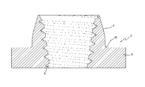
Fig. 1 shows an anchor body 2 formed from a metal flat
plate or bar. Through form drilling, friction heats up, softens
and displaces material through the thickness of the plate,
forming an opening through the plate and the boss section 4 as
one piece with the base section 6. Tapered threads 8 are made
by form threading. A radius 10 is provided where the boss
section meets the base section. The boss section 4 is tapered
and circular in cross-section.
Fig. 2 shows the anchor body 2 of Fig. 1 with straight
threads 12. The base section 6 at the bottom of the boss
section makes a 1:1 ratio with the thickness of the base
section. The anchor body is a single piece anchor, the threaded
-21-
CA 03014187 2018-08-09
WO 2017/139612 PCT/US2017/017419
portion and the bearing portion being in one piece. The anchor
2 works with the boss section 4 facing any direction, either
toward or away from the direction of the load. The anchor 2
advantageously provides teh threads 12 to be long enough to
create the required thread bearing area without increasing the
thickness of the base section 6. The anchor advantageously
provides thread engagement length greater than the thickness of
the base section 6.
Fig. 3 shows an anchor body 14 formed from form drilling
and form threading, as in the anchor 2. The boss section 16 has
no circular cross-section and is not tapered. A right angle
transition (no radius) is formed at the corner of the boss
section and the base section 6. Straight threads 12 are formed
from form threading.
Fig. 4 shows an anchor body 18 similar to the anchor 2 but
with reverse tapered threads 20.
Figs. 5A-5C show the anchor body 2 with straight threads 12
attached to a threaded rod 22, which is subjected to tensile
force. The thin wall portion 24 tends to spread radially
outwardly, decreasing the area of engagement of the threads 12
with threaded rod 22.
-22-
GA 03014187 2018-08-09
WO 2017/139612 PCT/US2017/017419
Fig. 5D shows the thin wall portion 24 being subject to
compression force within the concrete 23 toward the threaded rod
due to the tapered shape of the boss section 4, thereby
maintaining full contact of the threads 12 with the threaded rod
22.
Fig. 6A shows the anchor body 2 attached to a plastic plug
26 for attachment to a form board 28 prior to concrete being
poured. The plug positions the anchor at a sufficient depth in
the concrete where a breakout cone meets or exceeds the required
strength to carry a load. The plug has a main body portion 19
in the shape of a column 19 extending upwardly from a base
portion 21. The exterior shape of the main body portion 19 is
tapered, such as conical shaped, for easy removal from the
concrete. The exterior surface 29 of the side wall of the base
portion 21 is also tapered or conical shaped. The plug has a
threaded portion 27 that mates with the threads 12 of the anchor
to seal the threads 12 from the concrete. A portion of the
threaded portion 27 extends past the top surface of the anchor 2
to form the concrete.
Fig. 6B is a cross-section view through the anchor body 2
embedded in concrete 23 with a threaded rod 30 attached to the
anchor 2 after the plug 26 has been removed, along with the form
-23-
CA 03014187 2018-08-09
WO 2017/139612 PCT/US2017/017419
board 28 after the concrete 23 has cured. The fastener 30
extends past the top part of the anchor 2 into a threaded cavity
29 formed by the threaded portion 27.
Fig. 6C is a cross-sectional view of the plug and the
anchor body of Fig. 6A, except that the threaded portion 27 does
not extend past the top surface of the anchor body 2. The plug
includes a central opening for receiving a screw or nail for
attachment of the plug to the form board.
Fig. 6D shows the plug 26 embedded in concrete 23, with the
plug 26 removed after the concrete cured and the fastener 30
attached to the anchor body 2.
Fig. 7 shows an anchor body 32 supported by the plug 26.
The anchor body is a nut body portion 31 with an integrated
washer or flange portion 33.
Fig. 8A shows a plug 25 supporting a nut 34, which is used
as an anchor body to be embedded in concrete at a location that
will generate a sufficient breakout cone to support the load
designed for it. A nail secures the plug to the form board 28.
Fig. 8B shows the nut 34 embedded in concrete 23 and the
breakout cone 38 in the concrete 23 that the nut 34 will create
when placed under a load.
-24-
Fig. 9 is cross-sectional view of the plug 25 shown in Fig.
8A. A screw 40 is used to secure the plug to the form board.
The plug 25 includes a smooth cylindrical portion 42 attached
with interference/friction fit with the nut anchor body 34. The
plug 25 is similar to the plug 26. The shoulder 43 is in
sealing contact with the bottom surface 45 of the nut to seal
out the concrete.
Fig. 10 shows a plug 44 with a smooth cylindrical portion
46 and a threaded portion 48. A Nylon lock nut 50 used as an
anchor body includes a Nylon washer 52 in sealing attachment to
the smooth portion 46. The Nylon lock nut is conventional. A
nail 54 attaches the plug to the form board 28. The plug 44 is
similar to the plug 26.
Fig. 11 shows a plug 56 attached to a split nut 58 used as
an anchor body. The split nut 58 is disclosed in U.S. Pat. No.
9,222,251. A nail 54 or screw attaches the plug 56 to the form
board 28. The split nut sections 60 open radially when a
threaded rod is pushed up into it and return to their original
size when the threaded rod is pulled down, allowing for the
mating of the threads of the sections and the rod. The cap 62
is in sealing attachment to the threaded portion 64 to seal out
the concrete. The cap is
-25-
CA 3014187 2020-04-06
CA 03014187 2018-08-09
WO 2017/139612 PCT/US2017/017419
attached to the housing 66 with screws (not shown). The
shoulder 67 is in sealing contact with bottom surface of the
housing 69 of the housing 71 to seal out the concrete.
Fig. 12 shows a plug 68 supporting a split nut 70 with
sections 72 with multiple diameter threads 74. The cap 62 is in
sealing attachment to the smooth cylindrical portion 76 to seal
out the concrete. The nail 54 or screw attaches the plug 68 to
the form board 28.
Fig. 13A shows a split nut 78 with a spring 80 disposed in
the cap 82 in a compressed state.
Fig. 13B shows the spring in an expanded state after the
plug 68 is removed once the concrete 23 is cured. The split nut
sections 60 hold the spring 80 in place. A void 81 in the
concrete 23 is created after the plug 68 is removed after the
concrete has cured.
Fig. 13C shows a threaded rod 84 through the void 81 in the
concrete 23 and attached to the split nut sections 60 and
pushing the spring 80 into a compressed state, pushing the
threaded rod downwardly to help engagement between the split nut
section threads and the threads of the rod.
-26-
GA 03014187 2018-08-09
WO 2017/139612 PCT/US2017/017419
Fig. 14A shows the plug 56 attached to a split nut 86 with
a threaded cap 88, which is in sealing attachment to the plug
threaded portion 64 to seal out the concrete.
Fig. 14B shows the plug 56 attached to a split nut 90 with
a cap 92 without an opening on top, unlike the cap 88. The cap
92 has shoulder 94 extending radially outwardly to provide
additional bearing area positioned deeper into the concrete.
Fig. 14C shows the plug 56 attached to a split nut 96 with
a screwed-on cap 98.
Fig. 15 shows the plug 56 attached to a washer 100 and the
nut 34. The washer increases the bearing area of the nut.
Fig. 16 shows a plug 102 attached to the nut 34 and the
washer 100. The plug has stepped conical portion 104 concentric
with the main conical body 106. The conical portion 104 has a
larger diameter portion than the diameter of the opening of the
washer to help center the washer and seal the washer opening
from the concrete. A cylindrical portion 108 has a single turn
continuous thread 110. Engaging surfaces 112 and 114 seal the
concrete out from the threads 116.
Fig. 17 shows the plug 26 attached to the nut 34 and a U-
shaped metal bracket 118. The bracket 118 has an opening
through which the threaded portion 64 extends. The nut 34
-27-
GA 03014187 2018-08-09
WO 2017/139612 PCT/US2017/017419
secures the bracket 118 to the plug 26. When the plug is
removed from the cured concrete, a threaded fastener may be
threaded to the nut 34 to support a load.
Fig. 18 shows the plug 26 attached to the nut 34 and a cup-
shaped round bracket 120.
Fig. 19 shows the plug 26 attached to the nut 34 and a
circular stud rail assembly 120, comprising a round metal plate
122 with a central threaded boss 124 and anchor studs 126
attached to the plate 122 around the boss 124. A threaded rod
for supporting a load is threaded to the nut 34 but not to the
boss 124 after the concrete has cured and the plug 26 removed.
The nail 54 attaches the assembly to the form board 28. Each of
the anchor studs 126 includes a rod portion 125 and a head
portion 127. The anchor studs 126 are preferably arranged in a
circle at the peripheral edge portion of the metal plate 122.
Fig. 20 shows the plug attached to the nut 34 and an anchor
stud assembly 128, comprising a fixture or holder 130 holding
double ended anchor studs 132 around the nut 34. The nail 54 or
screw attaches the plug to the form board 28. The holder 130
includes a plurality of arms 129 extending outwardly from the
nut 34. Each of anchor studs 132 includes a rod portion 127 and
head portions 127 attached to the respective ends of the rod
-28-
CA 03014187 2018-08-09
WO 2017/139612 PCT/US2017/017419
portions 125. The anchor studs 132 are attached to the arms 129
at the respective rod portions 125.
Fig. 21A shows the shear cones generated by the anchor body
shown in Fig. 20 when embedded in the concrete 23 and subject to
a load. A larger effective shear cone 131 is generated with the
use of the double ended studs than the shear cone 133 of the nut
alone.
Fig. 21B shows the void 134 in the concrete 23 after the
plug 26 is removed.
Fig. 21C shows the threaded rod or bolt 136 screwed to the
nut 34. The threaded rod 136 is attached to a load (not shown)
that places the rod under tension.
Fig. 22 shows the plug 26 attached to the nut 34 and a
circular hollow metal cylinder 138 suspended around the plug by
a fixture or holder 140. The holder 140 includes a plurality of
arms 141 extending outwardly from the nut 34. The arms 141
support the hollow cylinder 138 at an intermediate portion so
that the hollow cylinder 138 partly encloses the plug 26. The
hollow cylinder 138 has an outer ring flange 142 extending
radially outwardly from the main body 144 and inner ring flange
146 extending radially inwardly from the main body 144.
Openings 148 and 150 are provided to allow the concrete to fill
-29-
CA 03014187 2018-08-09
WO 2017/139612 PCT/US2017/017419
up the interior of the hollow cylinder 138. The flanges 142 and
146 provide bearing surfaces for anchorage.
Fig. 23 shows a plug 152 with a cylindrical upper portion
154 and a threaded upper portion 156 of different diameters, the
cylindrical portion 154 being smaller than the threaded portion
156. A larger nut 158 and a smaller nut 160 are sealingly
attached to the cylindrical portion 154 and the threaded portion
156, respectively. The nuts 158 and 160 provide different
diameter threads for use with different diameter threaded rods
depending on the load requirement.
Fig. 24A shows the plug 152 attached to two formed anchor
bodies 162 and 164 of different size threads. The anchor bodies
162 and 164 are the same as the anchor body 2 shown in Fig. 2.
The anchor body 162 has a larger diameter thread than the anchor
body 164.
Fig. 24B shows the void 166 in the concrete 23 after the
plug 152 is removed.
Fig. 25 shows a plug 168 attached to the nut 34. The base
portion 170 is attached with nails 172 or screws to the form
board 28. The base portion 170 preferably includes openings for
receiving the nails or screws.
-30-
GA 03014187 2018-08-09
WO 2017/139612 PCT/US2017/017419
Fig. 26 shows a plug 172 attached to the formed anchor
bodies 162 and 164. A cylindrical portion 174 is sealingly
attached to the formed anchor body 162. A threaded portion 176
is sealingly attached to the formed anchor body 164. A magnet
178 attached to the bottom of the plug attaches the plug to a
steel formwork 180.
Fig. 27 shows three plugs 182, 184 and 186 having the same
structural details as the plug 26 in Fig. 7. Each plug has a
different color to designate thread size, type, depth and
intended use of the anchor in the concrete, such as fire, HVAC,
structural, etc. The plugs are attached to an anchor body 188
with three respective formed boss sections 190, 192 and 194 and
respective formed threads. Nails 196 or screws attach the plugs
to the form board 28. The plugs can remain in place until
needed. The bottom of the plug will be visible to the user
after the form board is removed when the concrete has cured.
Figs. 28 and 29 show a metallic plug 198 attached to the
nuts 158 and 160. A cylindrical portion 200 is attached to the
nut 158 and a threaded portion 202 is attached to the nut 160.
The nut 160 presses down on the nut 158 to seal the nut 158
against the shoulder 204. The bottom surface 206 of the nut 160
presses down on the top surface 208 of the nut 158 to seal
-31-
CA 03014187 2018-08-09
WO 2017/139612 PCT/US2017/017419
against the concrete. A pointed shaft 201 extending downwardly
from the base portion 21 is integrated with the plug and is used
to secure the plug to the form board 28.
Fig. 30 shows the plug 56 (also shown in Fig. 15) with a
sleeve 212 around the main body portion 214 of the plug. The
sleeve 212 has the same conical shape of the main body portion
214. The sleeve facilitates removal of the plug after the
concrete has cured since the plug is not in direct concrete
contact.
Fig. 31A shows the void 215 in the concrete 23 after the
plug 56 of Fig. 30 has been removed, leaving behind the sleeve
212.
Fig. 31B shows the void 215 in the concrete 23 with the
sleeve 212 removed from the concrete.
Fig. 32 shows a plug 216 attached to the washer 100 and the
nut 34. A main body portion 218 of the plug is cylindrical with
a sleeve 220. The sleeve facilitates removal of the plug after
the concrete has cured since the plug is not in direct concrete
contact.
Fig. 33 shows the arrangement of Fig. 30 where the sleeve
212 is used to hold the washer 100 in place.
-32-
GA 03014187 2018-08-09
WO 2017/139612 PCT/US2017/017419
Fig. 34 shows the arrangement of Fig. 32 where the sleeve
222 is overlapped and not continuous. The sleeve 222 may be
made to squeeze around the main body portion of the plug or with
a loose fit. Whether continuous or non-continuous (overlapped),
the sleeve may be removed or left in place after the concrete
has cured.
Fig. 35 shows the plug 26 attached to a wire coil or spring
224 at the threaded portion 27. A portion 226 of the spring
above the top of the plug 26 will be embedded in concrete. The
pitch of the spring is the same as the pitch of the threads 228
in the threaded portion 27, which is the pitch of the threaded
fastener to be installed. The portion 230 engaged with the
threads 228 will be embedded in concrete only on the outside.
Fig. 36 shows the spring 224 in the concrete 23 after the
plug 26 is removed after the concrete has cured. The portion
226 is completely embedded in concrete while the portion 230
below is only embedded on the outside. A void 232 in the
concrete 23 is shown after the plug is removed. The void 232
includes a portion within the spring portion 230. The portion
226 advantageously increases the pull-out strength of the spring
224, adding to the strength of the compression of the portion
230 against the concrete when the threaded fastener is
-33-
CA 03014187 2018-08-09
WO 2017/139612 PCT/US2017/017419
installed. Complete embedment of the spring portion 226 locks
the spring in the concrete. The spring coils stack on top of
each other so that concrete cannot penetrate to the inside of
the spring. Engagement of the concrete with each coil of the
spring is independent of the other coils of the spring.
Transfer of force from each thread pitch directly to concrete
occurs and each coil creates its own bearing surface interacting
with concrete when the threaded fastener is installed.
Fig. 37A shows the plug 25 attached to the spring 224 at
the cylindrical portion 42. The spring coils stack on top of
each other so that concrete cannot penetrate to the inside of
the spring.
Fig. 37E shows the void 233 after the plug 25 has been
removed after the concrete 23 has cured and a threaded rod 234
or bolt screwed into the coil 224. The pitch of the spring 224
is made to match the pitch of the threads of the threaded rod
234 or bolt.
Fig. 38 shows the plug 26 attached to a washer 236 and a
spring 238, which does not extend beyond the top of the plug.
The washer 236 provides an added bearing area. The washer 236
provides support to the spring 238.
-34-
CA 03014187 2018-08-09
WO 2017/139612 PCT/US2017/017419
Fig. 39 shows a plug 240 attached to a wire coil or spring
242 with multiple pitches so that different size fastener can be
used. The plug has a threaded portion 246, a conical transition
248 and cylindrical portion 250. The threaded portion 248 is
larger in diameter than the cylindrical portion's diameter. The
coils in the upper portion 252 of the spring 242 are stacked on
top of each other to seal the inside of the spring from the
concrete. The coils of the lower portion 254 of the spring are
spread apart and pressed against the threads of the threaded
portion 246 to seal the inside of the spring from the concrete.
The pitch of the lower portion 254 is larger than the pitch of
the upper portion 252 to advantageously permit the flexibility
of using a threaded fastener of a larger or smaller pitch and
diameter.
Fig. 40 shows the plug 240 removed after the concrete 23
has cured, creating a void 256 in the concrete. A fastener 258,
such as a threaded rod or bolt, is screwed into the lower
portion 254 of the spring.
Fig. 41 shows a smaller diameter fastener 260 screwed to
the upper portion 252 of the spring 242. The void 256 in the
concrete 23 allows access for the fastener 260.
-35-
CA 03014187 2018-08-09
WO 2017/139612 PCT/US2017/017419
Fig. 42A shows the plug 26 attached to a coiled wire 262
formed into the threads of the threaded portion 27 of the plug.
The wire has a shaped cross-section, such as square, diamond,
etc. and has the same shape as the threads of the threaded
section 27. The coils do not touch each other and concrete
fills up the space between the coils.
Fig. 42B shows the void 264 in the concrete after the plug
is removed after the concrete 23 has cured. The coiled wire 262
remains in the concrete.
Fig. 42C shows a fastener 266 screwed to the coiled wire
262 through the void 264 in the concrete 23.
Fig. 43 shows the plug 26 attached to a coiled wire 268
wound around the threaded portion 27 of the plug. The wire has
a shaped cross-section, such as square, diamond, etc., and has
the same shape as the threads of the threaded section 27. The
coils touch each other to seal the concrete from the inside of
the coiled wire.
Fig. 44A shows the plug 168 attached to a coil anchor body
230, such as a Hell-coil, at the threaded portion 27. The coils
do not touch each other to seal out fluid concrete. The plug
molds the concrete as well as holding and or suspending the coil
anchor body in-place before, during, and after the concrete is
-36-
GA 03014187 2018-013-09
WO 2017/139612 PCT/US2017/017419
poured. After the concrete has cured and hardened, the plug is
able to be removed and the Hell-coil can be used as an anchor
body. Once the plug is removed, a threaded rod will thread in
easily. The Heli-coil and concrete are together controlled by
the plug to form an anchor body. Both concrete and steel
surfaces are controlled to form dimension geometry with standard
tolerances such that are similar with standard nut and bolts
threaded geometry and tolerances. This same idea and invention
is consistent throughout the other anchor bodies provided herein
with different variations and configurations.
Fig. 44B shows a cross-section of the arrangement shown in
Fig. 44A, showing the coils not touching each other.
Fig. 45 shows the plug 26 attached to a metal sleeve 272
formed with threads threaded to the threaded portion 27. The
sleeve is a thin metal formed to create internal threads to hold
a fastener and external threads to create an external geometry
for the required concrete bearing area for the designed load for
the fastener. The sleeve is continuous without a break.
Fig. 46 shows the plug 26 attached to a split metal sleeve
274 formed with threads threaded to the threaded portion 27.
The sleeve 274 shows a vertical split 276.
-37-
GA 03014187 2018-08-09
WO 2017/139612 PCT/US2017/017419
Fig. 47 shows a cross-section of Figs. 45 and 46, showing
the internal and external threads of the sleeves 272 and 274.
Fig. 48 shows the plug removed, leaving a void 278 in the
concrete 23. The threaded sleeve 272 or 274 is left behind in
the concrete 23 to which a threaded fastener may be screwed.
Fig. 49A shows an inverted metal cup 280 with a bottom wall
282 and a side wall 284 formed with threads. The cup is
attached to the threaded portion 27.
Fig. 49B shows a plug 286 with a cylindrical portion 288
with a single turn thread (one revolution) 289. The inverted
metal cup 280 is screwed to the single thread so that the plug
can be removed with a single turn.
Fig. 50 shows a void 290 in the concrete 23 after the plug
26 or 286 is removed. The metal cup 280 is left behind in the
concrete to which a threaded fastener may be screwed.
Fig. 51 shows a void 292 in the concrete 23 after the plug
is removed after the concrete has cured. A tapered inverted
metal cup 294 is left behind in the concrete
Fig. 52 shows a threaded rod 296 with a threaded tapered
end portion 298 screwed to the tapered metal cup 294. The rod
296 is inserted into the void 292 in the concrete 23 through an
opening 300 at the bottom of the concrete created by the plug.
-38-
CA 03014187 2018-08-09
WO 2017/139612 PCT/US2017/017419
Fig. 53 shows the plug 26 attached to the form board 28.
The threaded portion 27 is used to form the threads in the
concrete.
Fig. 54 shows the void 302 in the concrete 23 after the
plug is removed after the concrete 23 has cured. The threaded
portion 27 forms the threads in the concrete to which a fastener
may be screwed.
Fig. 55A shows a plug 304 attached to a form board 28. A
single turn (one revolution) thread 306 or less at the end of
the end of the plug is used to form a corresponding single turn
thread or less in the concrete.
Fig. 55E shows the void 307 in the concrete 23 after the
plug is removed after the concrete has cured. The single turn
thread 306 is formed in the concrete 23.
Fig. 550 show a fastener 308 threaded to the single turn
thread 306 in the concrete 23.
Fig. 56 shows the plug 26 with the threaded portion 27
wrapped in TEFLON tape 310 to create a non-structural barrier
between the plug and the concrete. The tape 310 provides for
easier removal of the plug after the concrete has cured.
-39-
GA 03014187 2018-08-09
WO 2017/139612
PCT/US2017/017419
Fig. 57 shows the void 312 in the concrete 23 after the
plug is removed after the concrete has cured. The non-stick
tape 310 remains in the threads formed in the concrete.
Fig. 58 shows the void 312 in the concrete 23 with the non-
stick tape 310 removed from the formed threads in the concrete
23.
Fig. 59 shows the plug 26 with the threaded portion wrapped
with a thin metallic foil 314 to create a barrier between the
threaded portion 27 and the concrete.
Fig. 60 shows the void 316 in the concrete 23 after the
plug is removed after the concrete has cured. The metallic foil
314 remains in the threads formed in the concrete.
Fig. 61 shows the plug 168 with the threaded portion 27.
The base portion 170 is attached to the form board 28 with nails
172. A spring 318 with multiple diameters and pitches is
attached to the threaded portion 27. An expansion plug 320 is
attached at the smaller diameter portion 322 of the spring. The
expansion plug 320 expands the portion 322 to a larger diameter
equal to the diameter of the expansion plug 320. A metal washer
324 is supported by a peripheral shoulder 326 at the bottom of
the threaded portion 27. A cap 328 seals the washer, spring and
the expansion plug from the concrete. A cavity 330 is provided
-40-
GA 03014187 2018-08-09
WO 2017/139612 PCT/US2017/017419
to receive the expansion plug 320 and when the threaded fastener
is installed and pushes the expansion plug 320 into the cavity
330. The portion 322 contracts to its original diameter when
the expansion plug 320 is pushed out. The cap 328 has clip
portions 332 that hold the washer in place.
Fig. 62 shows the void 334 in the concrete 23 after the
plug is removed after the concrete has cured. The cap, spring,
expansion plug and the washer remain behind. The bottom coil
336 is supported by the top surface 338 of the washer since the
diameter of the opening 340 of the washer is smaller than the
outer diameter of the lower portion 342 of the spring 318.
Fig. 63 shows the threaded rod 344 inserted through the
void 334 in the concrete 23 and pushing the expansion plug 320
into the cavity 330, allowing the smaller diameter portion 322
to contract around and grab the threaded rod. The threaded rod
344 does not have to be turned for attachment to the spring.
Simply pushing the expansion plug into the cavity 330 will allow
the expanded spring portion that was expanded by the expansion
plug to contract once the expansion plug is pushed out and
attaches to the threaded rod without rotating the threaded rod
to engage the threads of the threaded rod with the portion 322.
-41-
GA 03014187 2018-08-09
WO 2017/139612 PCT/US2017/017419
Fig. 64 shows the expansion plug 320 completely displaced
from the spring portion 322, thereby allowing the spring portion
322 to grab the threaded rod.
Fig. 65 shows an anchor support 346 including a base 348
threaded to an extension tube 350 at a bottom end and a washer
352 at another end. The base is attached to the form board 28
by screws or nails 353. A central opening 355 may also be used
with a nail or screw to attach the base to the form board. The
extension tube 350 is advantageously detachable from the base
348 to gain access to the opening 355. A spring 354 is
supported by the top surface 356 of the washer. A cap 358
encloses and seals the spring and the washer from the concrete.
Resilient fingers 360 lock the cap 358 to the washer. The
spring has a dead portion 362 engaging an inner surface of the
cap and is shaped to prevent vertical and horizontal movement
within the cap. A live portion 364 of the spring is expanded by
an expansion plug 366. A cavity 367 at the top of the cap is
provided to receive the expansion plug after being pushed up by
a fastener. The cap 358 advantageously centers the spring 354
and holds it against the washer 352.
Fig. 66 shows a void 368 in the concrete 23 after the base
348 is removed after the concrete has cured. The extension tube
-42-
CA 03014187 2018-08-09
WO 2017/139612 PCT/US2017/017419
350 remains in the concrete 23 to provide access for a fastener
to attach to the spring 354.
Fig. 67 shows a fastener 370 pushing the expansion plug 366
through the live portion 364 of the spring and into the cavity
367.
Fig. 68 shows the expansion plug 366 completely out of the
live portion 364 of the spring and occupying the cavity 367.
Fig. 69 shows the plug 168 with the threaded portion 27
attached to a metal washer 372, which has a partly threaded
opening 374. The threaded portion 27 does not extend through
the thickness of the washer. A spring 376 with an upper dead
portion 378 and a lower live portion 380 is disposed inside a
cap 382 that seals the washer and the spring from the concrete.
An expansion plug 384 expands the live portion 380 to a larger
diameter.
Fig. 70 shows the void 386 in the concrete after the plug
is removed after the concrete has cured. A fastener 388 has
pushed the expansion plug into the dead portion of the spring,
allowing the live portion 380 to revert to its original diameter
and grab the fastener. The threads 390 in the opening 374 may
also be used to attach a larger diameter fastener.
-43-
CA 03014187 2018-08-09
WO 2017/139612 PCT/US2017/017419
Fig. 71A shows a plug 392 without a base portion. The plug
392 has a main body portion 393, preferably columnar in shape.
A nail or screw attaches the plug to the form board 28. The
plug is conical with a threaded end portion 394 for forming
threads in the concrete.
Fig. 71B shows a taller plug 392 with a wider bottom end
for stability.
Fig. 71C shows the void 396 in the concrete 23 after the
plug is removed after the concrete has cured. Threads 397 are
formed in the concrete by the threaded end portion 394.
Fig. 71D shows a fastener 398 screwed to the concrete
threads 397.
Fig. 72 shows an anchor support 402 including a base 404
threaded to an extension tube 406 at a bottom end and a washer
408 at another end. The base is attached to the form board 28
with a single screw 410 or nail through an opening 411 in the
center of the base. The tube 406 is removably attached to the
base 404 to gain access to the opening 411 to attach the base to
the form board. A nut 412 is supported by the washer. A cap
414 encloses and seals the nut from the concrete. Resilient
fingers 416 lock the cap to the washer. The washer may be
-44-
CA 03014187 2018-08-09
WO 2017/139612 PCT/US2017/017419
integrated with the expansion tube 406 instead of being a
separate unit threaded to the expansion tube.
Fig. 73 shows the void 418 in the concrete 23 after the
base 404 is unscrewed from the extension tube 406.
Fig. 74 shows a base 420 attached to the form board 28 with
screws or nails 422 through openings along the peripheral edge
of the base. The base 420 is attached to the extension tube 406
in the same manner as the base 404.
Fig. 75A shows a plug 422 with a large diameter central
opening 424 sufficient to accommodate the size of a fastener for
attachment to the anchor body 426 after the concrete has cured.
The plug has a base portion 428 attached to the form board 28
with screws or nails 430. The plug has a main body 432 that is
conical in shape. A threaded portion 434 holds the anchor body
426. The anchor body includes multiple diameter threaded bores
436, 438 and 440 for holding a fastener.
Fig. 75B shows a fastener 442 attached to the anchor body
426. The plug 422 does not have to be removed after the
concrete 23 has cured since the opening 424 is large enough to
allow the fastener 442 to reach the anchor body 426. The plug
422 may be removed to gain access to the threaded bore 436, to
which the plug is attached.
-45-
GA 03014187 2018-08-09
WO 2017/139612 PCT/US2017/017419
Fig. 76A shows the plug 422 attached to an anchor body 444
with a through opening 446 with multiple diameter threaded bores
448 and 450. A tape, sticker or other adhesive strip 452 is
used to seal the top opening from the concrete.
Fig. 76B shows a fastener 454 attached to the smaller
diameter bore 450. The plug 422 may remain in the concrete 23.
Fig. 760 shows a larger diameter fastener 456 attached to
the larger diameter bore 448. The plug 422 has been removed,
creating a void 458 in the concrete 23 of sufficient diameter to
accommodate the larger diameter fastener 456.
Fig. 77A shows the plug 422 with the anchor body 444
provided with a compressible foam adhesive strip 460 to seal the
opening 446 from the concrete.
Fig. 77B shows the anchor body 444 attached to a fastener
462. The end of the fastener compresses the foam strip 460 and
allows the end of the fastener to extend past the anchor body
444 to ensure complete engagement of the threads. The plug 422
may remain in the concrete 23. The foam adhesive has sufficient
thickness of at least one thread pitch to allow the end of the
fastener 462 to compress the foam adhesive into the concrete as
the fastener extends past the top of the anchor body at least
one thread pitch.
-46-
CA 03014187 2018-08-09
WO 2017/139612 PCT/US2017/017419
Fig. 78A shows the plug 464 attached to an anchor body 466,
which has multiple diameter bores 468, 470 and 472. A flange
portion 474 extends radially outwardly from the main body
portion 476 to provide an additional bearing area in the
concrete. The base portion 478 has a circumferential slit 480
or weakened section at the bottom of the main body portion 482
to allow the base portion to break away from the main body
portion when the form board 28 is removed after the concrete has
cured. The plug 482 is attached to the form board 28 with
screws. The main body portion has a central opening 484 large
enough in diameter to allow a fastener access to the threaded
bores 470 and 472.
Fig. 78B shows the base portion 478 broken off from the
main body portion 482, leaving behind a void 483 in the concrete
23. The base portion 478 is shown still attached to the form
board 28 when the form board is removed after the concrete has
cured, leaving the main body portion 472 in the concrete 23.
Fig. 78C shows a fastener 486 attached to the threaded bore
472. Access is provide through the opening 484 in the main body
portion 482, which may also be removed from the concrete 23 to
gain access to the threaded bore 468.
-47-
CA 03014187 2018-08-09
WO 2017/139612 PCT/US2017/017419
Fig. 79A shows the plug 422 attached to a split nut 488 at
the threaded portion 434. The housing 490 has a threaded
opening 492 that screws to the threaded portion 434. The split
nut 488 operates in the same way as the split nut 90 shown in
Fig. 14B. The cap 92 has shoulder 94 extending radially
outwardly to provide additional bearing area positioned deeper
into the concrete.
Fig. 79B shows a fastener 494 attached to the split nut
sections 60. The plug 422 may remain in the concrete 23.
Fig. 80A shows the plug 496 attached to an anchor body 498
at the threaded portion 500. The anchor body includes a
plurality of threaded bores 502 and 504 with different
diameters. An extension tube 506 is threaded to the base 506,
which is attached to the form board 28 by a nail 510 through a
central opening 512 in the base.
Fig. 80B shows a fastener 514 attached to the larger
diameter threaded bore 502. The base 508 has been removed,
leaving a void 516 in the concrete 23 after the concrete has
cured. The Inner diameter of the extension tube 506 is large
enough to accommodate the larger diameter threaded rod sized for
the larger diameter threaded bore 502.
-48-
GA 03014187 2018-08-09
WO 2017/139612 PCT/US2017/017419
Fig. 81A shows a plug 518 attached to an anchor body 520.
The plug is attached to the form board 28 with a screw 522
through a central opening 524. The anchor body has a
cylindrical recess 526 with a circumferential groove 528. The
upper portion of the plug 518 is cylindrical and is received
within the recess 526. A circumferential groove 530 cooperates
with the groove 528 to hold a compressible or elastic ring 532
to hold the anchor body 520 and the plug 518 together.
Fig. 81B shows the plug 518 separated from the anchor body
520 after the concrete 23 has cured, leaving a void 534 in the
concrete. The plug 518 remains attached to the form board 28.
The ring 532 is squeezed out of the groove 528 during the
separation.
Fig. 81C shows a cylindrical nut 536 with a circumferential
locking groove 538 holding a locking split ring 540. The cross-
sectional shape of the groove 538 is such that when the nut 536
is pushed into the recess 526, the ring 540 retracts into the
groove 538, allowing the nut 536 to enter the recess 526. When
the groove 538 lines up with the groove 528, the ring 540
expands into the groove 528. When a downward force is applied
through the fastener 542, the ring locks between the grooves 528
and 538. The operation of the grooves 528 and 538 with the ring
-49-
540 is fully disclosed in U.S. Pat. No. 6,161,350.
Fig. 81D shows the fastener 542 tight against the top wall
544 of the anchor body, forcing the nut 536 downwardly thereby
to lock with the ring 540 between the grooves 528 and 538,
removing any looseness between the nut and the anchor body. The
downward force exerted by a load attached to the fastener
(threaded rod) 542 will further contribute to the tightness of
the connection between the nut and the anchor body.
Fig. 81E is an enlarged detail taken from Fig. 81D. Terms
referring to "locking geometry" or "geometry" in Figs. 81C, 81D,
82A-82E and 83A-83D refer to the locking interplay between the
grooves 528 and 538 and the ring 540 when there is relative
motion in one direction.
Fig. 82A shows the plug 518 attached to the form board 28
with the screw 522 (shown in Fig. 81A).
Fig. 82B shows the void 546 in the concrete 23 after the
plug is removed after the concrete has cured. The ring 532
creates the groove 528 in the concrete.
Fig. 82C shows the nut 536 with the groove 538 and the
locking split (C-ring) ring 540. The fastener 542 is attached
to the nut 536.
-50-
CA 3014187 2020-04-06
CA 03014187 2018-08-09
WO 2017/139612 PCT/US2017/017419
Fig. 82D shows the nut 536 locked in place in the concrete
23, with the groove 528 in the concrete and the groove 538 in
the nut In locking position with the split ring 540.
Fig. 82E shows the fastener 542 and the nut 536 made as
one-piece unit 537.
Fig. 83A shows a plug 548 and an anchor body 550 that are
identical to the plug 518 and the anchor body 520, except with
the addition of another set of grooves 528 and 530 and the
compressible ring 532.
Fig. 838 shows a nut 552 received within the anchor body
550. The cylindrical nut 552 is identical to the nut 536,
except with the addition of another set of groove 538 and the
split ring 540. The nut 552 and the anchor body 550 provide
greater load capacity due to the addition of another split ring
and the corresponding grooves. The void 534 in the concrete 23
is created when the plug 548 is removed after the concrete has
cured.
Fig. 83C shows a plug 554, which is identical to the plug
518 except for the addition of another set of groove 528 and the
compressible ring 532.
Fig. 83D shows a nut 556, which is identical to the nut 536
except with the addition of one set of except with the addition
-51-
GA 03014187 2018-08-09
WO 2017/139612 PCT/US2017/017419
of another set of groove 538 and the split ring 540. An
additional groove 528 is created in the concrete. A void 558 in
the concrete 23 is created after the plug 554 is removed when
the concrete has cured.
Fig. 84A shows a plug attached to a nut 562. The plug has
a base portion 564 attached to the form board 28 with nails.
The plug has a central opening 566 with a diameter sufficient
for an anchor rod or fastener to pass through to reach the nut
562. An upper portion of the plug includes outwardly extending
arms 568 to support the nut 562. The arms 568 are L-shaped with
vertical portions 570 that support the nut 562 radially and
horizontal portions 572 support the nut vertically. Partly
circular members 574 join every other pair of the arms 568 and
includes a portion of a single revolution male thread . A cap
576 seals the upper portion of the nut 562 from the concrete.
The lower portion 578 of the nut seals with the upper portion
579 of the plug. The cap includes an upper cavity 580 above the
nut to allow a fastener 782 to extend past the top of the nut.
The cap includes a plurality of fingers 584 extending downwardly
with portions of a single revolution female thread 586 that mate
with the male thread 575. Turning the thread 586 in a
tightening direction with respect to the thread 575 will force
-52-
CA 03014187 2018-08-09
WO 2017/139612 PCT/US2017/017419
the nut via the radial wall portion 588 to press on the top
surface of the nut, causing a seal at the top surface and
forcing the lower portion 578 of the nut to press on the upper
portion 579 of the plug.
Fig. 84B shows the plug 560 and the cap 576 in perspective
view. The nut diameter and thread size may be indicated on the
top wall portion 590 as generally indicated at 592. The cap may
also be color coded to indicate the size and type of the threads
of the anchor body, capacity of the anchor body, intended use of
the anchor body (such for supporting HVAC components, plumbing,
electrical trays, fire alarm equipment and wiring, etc.), and
type of the anchor body.
Fig. 84C shows the fastener 582 screwed to the nut 562 and
extends into the cavity 580. This ensures full engagement of
the threads of the nut and the fastener.
Fig. 84D show a breakout cone 594 in concrete 23 generated
by the nut 562 under load.
Fig. 84E shows the lower bearing surface 594 of the nut 562
that will be in direct contact with the concrete when embedded
in concrete.
Fig. 85A shows a plug 596 similar to the plug 560 except
that two nuts 562 and 597 are attached to the plug 596. The nut
-53-
CA 03014187 2018-08-09
WO 2017/139612 PCT/US2017/017419
597 has a smaller threaded opening 598 than the nut 562 to
provide use for different sized fasteners. A cap 600 is
provided to seal the nuts 597 and 562 from the concrete. The
cap 600 is structurally the same as the cap 576 in terms of the
connection to plug 596. Tightening the cap 600 to the plug 596
presses the upper nut 597 against the lower nut 562 to seal the
interior of the nuts from the concrete.
Fig. 85B shows at 602 the diameters and thread sizes of the
nuts.
Fig. 85C shows a fastener 604 attached to the smaller
diameter nut 598. The end of the fastener extends past the nut
598 into the cavity 580 to ensure complete engagement of the
threads of the nut and the fastener.
Fig. 85D shows slots 606 in the side wall of the cap next
to the flat sides of the nut 596 to allow the concrete to fill
the void on the side of the flat faces of the nut to prevent the
nut from turning when the fastener is attached.
Fig. 86A shows a circumferential slit 608 around the
peripheral edge portion 614 of opening 610 in the base portion
612 of the plug 596. The slit 608 is preferably sized the same
as the head of the screw or nail 616.
-54-
CA 03014187 2018-08-09
WO 2017/139612 PCT/US2017/017419
Fig. 86B shows the weakened peripheral portion 614 around
the opening 610 that breaks off with the screw 616 when the form
board 28 is removed. The weakened portion 614 along with screw
616 stay with the form board 28. The peripheral edge portion
614 is preferably the size of a head of the screw 616 to aid the
screw to break through the base portion 612 when the form board
is removed from the cured concrete.
Fig. 87A shows a plug 616 similar to the plug 560 except
that the base portion 564 is a removable base member 618, which
includes a cylindrical portion 620 sealingly received with the
opening 566 with a close fit. A screw 622 or nail through a
central opening in the cylindrical portion 620 attaches the plug
616 to the form board 28.
Fig. 87B shows the removal of the form board 28 after the
concrete 23 has cured. The base member 618 stays attached to
the form board 28, leaving the rest of the plug 616 behind in
the concrete.
Fig. 88A shows a plug 626 similar to the plug 616 except
that the removable base member 618 is a threaded removable base
628, which is threaded to a bottom end portion of the opening
566.
-55-
GA 03014187 2018-08-09
WO 2017/139612 PCT/US2017/017419
Fig. 88B shows the removal of the form board 28 after the
concrete 23 has cured. The base member 628 is then removed by
unthreading from the threads 630 at the bottom end portion of
the opening 566. The rest of the plug 626 is embedded in
concrete.
Fig. 89A shows a plug 630 with a base portion 632 with a
central opening 634. A weakened circumferential flange 636
supports the head of a screw 638 that attaches the plug to the
form board 28. The circumferential flange 636 extends radially
into the opening 634. The weakened flange is configured to
break to allow the head of the screw or nail 638 to pass through
the opening 634 when the form board 28 is removed after the
cured has cured. The flange 636 is weakened with a
circumferential slit 639 (similar to the slit 608 shown in Fig.
86A) preferably has the same size as the head of the screw.
Fig. 89B shows the plug 630 embedded in the concrete 23.
When the form board 28 is removed from the concrete, the
weakened circumferential flange 636 gives way to the head of the
screw 638, which remains attached to the form board 28. The
plug 630 will be removed to gain access to the anchor body 640.
Fig. 90A shows a plug 642 with a base portion 644 with a
central opening 646 through which a screw or nail 648 extends to
-56-
GA 03014187 2018-08-09
WO 2017/139612 PCT/US2017/017419
attach the plug to the form board 28. A weakened portion 650
closes the bottom of an opening 652. The weakened portion is
configured to break and separate from the plug to open the
opening 652 at the bottom to allow the threaded portion of a
fastener access to the opening 652 and attach to the anchor body
640. A circular slit 654 having the same diameter as the
opening 652 that extends partway into the thickness of the
portion 650 may be used to weaken the portion and thus
facilitate the breaking of the weakened portion from the plug to
expose the opening 652 when the form board is removed.
Fig. 90B shows the plug 652 embedded in the concrete 23
with the form board 28 separated from the concrete with the
weakened portion 650 remaining attached to the form board with
the screw 648. The opening at the bottom of the opening 652 is
cleared of the weakened portion 650, allowing a threaded rod to
enter and attach to the anchor body without removing the plug
from the concrete.
Fig. 91A shows a plug 656 attached to the form board 28
through a central opening 658 in the base portion 660, which is
attached to main body portion 662 of the plug with thin members
664 configured to break and separate from the plug when the form
board 28 is removed from the concrete after the concrete has
-57-
GA 03014187 2018-08-09
WO 2017/139612 PCT/US2017/017419
cured. The connection between the main body portion 662 and the
base portion 660 is through the edges of the thin members 664.
Fig. 91B shows the plug 656 embedded in the concrete 23
with the base portion 660 broken off from the plug 656 when the
form board 28 is removed from the concrete. The base portion
660 remains attached to the form board 28 with the screw 638.
The separation of the base portion 660 from the plug clears the
bottom of the opening 652, providing access to the anchor body
640 to a threaded rod, bolt, fastener, etc. A void 666
corresponding to the outside shape of the base portion 660 is
created in the concrete 23 when the base portion 660 is broken
off and separated from the plug 653. Since access to the
opening 652 is provided after the from board 28 is removed, the
plug 656 does not have to be removed from the concrete 23 so
that the main body portion 662 of the plug does not have to be
conical or tapered. The color of the main body portion 662 may
be color coded to indicate the size and type of the threads of
the anchor body 640, capacity of the anchor body 640, intended
use of the anchor body (such for supporting HVAC components,
plumbing, electrical trays, fire alarm equipment and wiring,
etc.), and type of the anchor body.
-58-
CA 03014187 2018-08-09
WO 2017/139612 PCT/US2017/017419
The various features disclosed herein with particular
embodiments of the plugs and the anchor bodies should be
understood to be equally applicable to all other embodiments
even though not specifically disclosed in combination with those
embodiments.
The various embodiments of the plugs disclosed herein are
means for positioning anchor bodies in concrete and providing an
access opening to the anchor bodies.
While this invention has been described as having preferred
design, it is understood that it is capable of further
modification, uses and/or adaptations following in general the
principle of the invention and including such departures from
the present disclosure as come within known or customary
practice in the art to which the invention pertains, and as may
be applied to the essential features set forth, and fall within
the scope of the invention or the limits of the appended claims.
-59-