Note: Descriptions are shown in the official language in which they were submitted.
CA 03014278 2018-08-10
WO 2017/139549 PCT/US2017/017333
SPEED CONTROLLED SWITCHING SYSTEM FOR A RIDE-ON VEHICLE
DESCRIPTION
CROSS-REFERENCE TO RELATED APPLICATIONS
[0001] This application claims the benefit of U.S. Provisional Patent
Application No.
62/294,519, filed February 12, 2016; U.S. Provisional Patent Application No.
62/305,776, filed
March 9, 2016; and U.S. Patent Application No. 15/428,756, filed February 9,
2017, all of which
are expressly incorporated herein by reference and made a part hereof.
FEDERALLY SPONSORED RESEARCH OR DEVELOPMENT
[0002] Not Applicable.
TECHNICAL FIELD
[0003] The present disclosure generally relates to a battery-powered
vehicle, and in
particular, to a speed controlled switching system for a battery-powered ride-
on vehicle.
BACKGROUND
[0004] Battery powered ride-on vehicles are known. However, standard
battery powered
ride-on vehicles have numerous deficiencies and limitations. The present
invention seeks to
overcome certain of these limitations and other drawbacks of the prior art,
and to provide new
features not heretofore available. A full discussion of the features and
advantages of the present
invention is deferred to the following detailed description, which proceeds
with reference to the
accompanying drawings.
SUMMARY
100051 According to one embodiment, the disclosed subject technology
relates to a battery-
powered ride-on vehicle.
[0006] The disclosed technology further relates to a battery-powered
vehicle, comprising: a
vehicle body; a plurality of wheels supporting the vehicle body; a motor
connected to at least one
of the plurality of wheels; a remote charging dock on an exterior of the
vehicle body, the remote
1
CA 03014278 2018-08-10
WO 2017/139549 PCT/US2017/017333
charging dock having remote charging terminals; a first controller in
electrical communication
with the remote charging dock; a battery port extending into the vehicle body,
the battery port
having a battery dock and battery dock terminals; a second controller in
electrical
communication with the battery dock; a first wiring harness connecting the
remote charging dock
with the battery dock, wherein the first wiring harness has a power line to
allow current to flow
between the battery dock and the remote charging dock, and a communication
line in the first
wiring harness to allow data to be transmitted between the first controller
and the second
controller; a charger having a charger plug and associated charger terminals;
and, a removable
and rechargeable battery having battery terminals, wherein the battery is
configured to be
charged in the battery port when (a) the battery is positioned in the battery
port and the battery
terminals electrically and mechanically mate with the battery dock terminals,
and (b) when the
charger terminals of the charger are connected to the remote charging
terminals of the remote
charging dock, and wherein the battery is configured to be charged remote from
the vehicle when
(a) the battery is removed from the battery port and the battery terminals
electrically and
mechanically mate with the charger terminals for charging outside the battery
port.
[0007] The disclosed technology further relates to a battery-powered
vehicle, comprising: a
vehicle body; a plurality of wheels supporting the vehicle body, a motor
connected to at least one
of the plurality of wheels; a battery port having a battery dock and battery
dock terminals; a
remote charging dock on an exterior of the vehicle body, the remote charging
dock having
remote charging terminals; a charger having a charger plug and associated
charger terminals;
and, a removable and rechargeable battery having battery terminals, wherein
the battery is
configured to be positioned in the battery port for charging in the battery
port and to have the
battery terminals electrically and mechanically mate with the battery dock
terminals, and
wherein the battery is configured to be removed from the battery port and to
have the battery
terminals electrically and mechanically mate with the charger terminals for
charging outside the
battery port.
[0008] The disclosed technology further relates to a battery-powered
vehicle, comprising: a
vehicle body; a plurality of wheels supporting the vehicle body; a motor
connected to at least one
of the plurality of wheels; a battery port having a battery dock and battery
dock terminals; a
remote charging dock on an exterior of the vehicle body, the remote charging
dock having
remote charging terminals; a first wiring harness connecting the remote
charging dock with the
2
CA 03014278 2018-08-10
WO 2017/139549 PCT/US2017/017333
battery dock, wherein the first wiring harness has a power line to allow
current to flow between
the battery dock and the remote charging dock, and a communication line in the
first wiring
harness to allow data to be transmitted between the battery dock and the
remote charging dock; a
charger having a charger plug and associated charger terminals; a rechargeable
battery having
battery terminals, wherein the battery is configured to be positioned in the
battery port for
charging in the battery port and to have the battery terminals electrically
and mechanically mate
with the battery dock terminals; a pedal switch, a pedal switch controller,
and a second wiring
harness connecting the pedal switch controller with a second controller in the
battery dock,
wherein the second wiring harness has a power line to allow current to flow
between the battery
dock and the pedal switch controller, and a communication line in the second
wiring harness to
allow data to be transmitted between the second controller in the battery dock
and the pedal
switch controller.
[0009] The disclosed technology further relates to a battery-powered
vehicle having a first
motor connected to a first wheel and a second motor connected to a second
wheel.
[0010] The disclosed technology further relates to a battery-powered
vehicle wherein the
charger terminals and the battery dock terminals have a first terminal
configuration, wherein the
remote charging terminals and the battery terminals have a second terminal
configuration,
wherein the first terminal configuration is different from the second terminal
configuration, and
wherein the terminals of the first terminal configuration are adapted to mate
with the terminals of
the second terminal configuration.
[0011] The disclosed technology further relates to a battery-powered
vehicle having a third
controller in the charger and a fourth controller in the battery, the third
controller being
electrically connected to the first controller when the charger is plugged
into the remote charging
dock, and the fourth controller communicating with one of the second
controller in the battery
dock when the battery is connected to the battery dock, and the third
controller in the charger.
[0012] The disclosed technology further relates to a battery-powered
vehicle having a pedal
switch, a pedal switch controller, and a second wiring harness connecting the
pedal switch
controller with a second controller in the battery dock, wherein the second
wiring harness has a
power line to allow current to flow between the battery dock and the pedal
switch controller, and
a communication line in the second wiring harness to allow data to be
transmitted between the
second controller in the battery dock and the pedal switch controller.
3
CA 03014278 2018-08-10
WO 2017/139549 PCT/US2017/017333
[0013] The disclosed technology further relates to a battery-powered
vehicle wherein one of
the second controller in the battery dock and the pedal switch controller
prevents the release of
current to all motors when the charger is connected to the remote charging
dock. The disclosed
technology further relates to a battery-powered vehicle wherein the charger
terminals of the
charger are connected to the remote charging terminals of the remote charging
dock for charging
the battery in the battery port.
[0014] The disclosed technology further relates to a battery-powered
vehicle having a first
wiring harness connecting the remote charging dock with the battery dock,
wherein the first
wiring harness has a power line to allow current to flow between the battery
dock and the remote
charging dock, and a communication line in the first wiring harness to allow
data to be
transmitted between the battery dock and the remote charging dock.
[0015] The disclosed technology further relates to a battery-powered
vehicle having a first
controller in the remote charging dock and a second controller in the battery
dock, the
communication line electrically connecting the first controller to the second
controller. The
disclosed technology further relates to a battery-powered vehicle having a
third controller in the
charger that monitors battery parameters based on data transmitted from the
fourth controller to
the third controller through the communication line. The disclosed technology
further relates to
a battery-powered vehicle wherein the third controller in the charger monitors
battery parameters
based on data transmitted from the fourth controller to the third controller
when the battery
terminals are electrically and mechanically connected with the charger
terminals.
[0016] The disclosed technology further relates to a battery-powered
vehicle wherein one of
a second controller in the battery dock and the pedal switch controller
prevents the release of
current to the motor when the charger is connected to the remote charging
dock.
[0017] The disclosed technology further relates to a ride-on vehicle having
a speed
controlled switching system, comprising: a vehicle body having a driver's seat
for a rider; a
plurality of wheels supporting the vehicle body; a motor connected to at least
one of the plurality
of wheels; a battery electrically connected to the motor; a direction switch
assembly electrically
connected between the battery and the motor, the direction switch assembly
having a forward
button, a reverse button, a first switch, a second switch, and a rocker plate
between the forward
and reverse buttons and the first and second switches; and, a speed switch
electrically connected
between the direction switch assembly and the motor, the speed switch being
separate from the
4
IF
CA 03014278 2018-08-10
WO 2017/139549 PCT/US2017/017333
direction switch assembly, and the speed switch having a high speed setting
and a low speed
setting, wherein when the reverse button of the direction switch assembly is
actuated it removes
control of a speed of the motor from the speed switch, and wherein when the
forward button of
the direction switch assembly is actuated it causes the speed switch to
control the speed of the
motor.
[0018] The disclosed technology further relates to a ride-on vehicle having
a speed
controlled switching system, comprising: a vehicle body having a driver's seat
for a rider; a
plurality of wheels supporting the vehicle body; a motor connected to at least
one of the plurality
of wheels; a battery electrically connected to the motor; a direction switch
assembly electrically
connected between the battery and the motor, the direction switch assembly
having a forward
button and a reverse button adjacent the forward button; and, a speed switch
electrically
connected between the direction switch assembly and the motor, the speed
switch being separate
from the direction switch assembly, wherein when the reverse button of the
direction switch
assembly is actuated it removes control of a speed of the motor from the speed
switch, and
wherein when the forward button of the direction switch assembly is actuated
it causes the speed
switch to control the speed of the motor.
[0019] The disclosed technology further relates to a ride-on vehicle having
a speed
controlled switching system, comprising: a vehicle body having a driver's seat
for a rider; a
plurality of wheels supporting the vehicle body; a motor connected to at least
one of the plurality
of wheels; a battery electrically connected to the motor; a direction switch
assembly electrically
connected between the battery and the motor, the direction switch assembly
having an
independent forward button and an independent reverse button adjacent the
forward button; and,
a speed switch electrically connected between the direction switch assembly
and the motor, the
speed switch separate from the direction switch assembly, the speed switch
having a low speed
setting and a high speed setting, wherein the direction switch is proximal the
driver's seat in the
vehicle body, and wherein the speed switch is distal the driver's seat and
generally not accessible
by a rider seated in the driver's seat.
[0020] The disclosed technology further relates to a ride-on vehicle
wherein the first switch
of the direction switch assembly controls the polarity of the current sent to
the motor. The
disclosed technology further relates to a ride-on vehicle wherein when the
first switch is in a first
IP
CA 03014278 2018-08-10
WO 2017/139549 PCT/US2017/017333
position the current provided to the motor has a first polarity, and when the
first switch is in a
second position the current provided to the motor has a second polarity
opposite the first polarity.
[0021] The disclosed technology further relates to a ride-on vehicle
wherein actuation of the
forward button operates to actuate the first switch to a first position and to
actuate the second
switch to a first position, and wherein actuation of the reverse button
operates to actuate the first
switch to a second position and to actuate the second switch to a second
position.
100221 The disclosed technology further relates to a ride-on vehicle
wherein the direction
switch assembly is proximal the driver's seat in the vehicle body, and wherein
the speed switch
is distal the driver's seat and generally not accessible by a rider seated in
the driver's seat.
[0023] The disclosed technology further relates to a ride-on vehicle having
a second motor
connected to at least one of the plurality of wheels. The disclosed technology
further relates to a
ride-on vehicle wherein a voltage is provided to the motors in parallel when
the forward button is
actuated and when the speed switch is in the high speed setting, wherein the
voltage is provided
to the motors in series when the forward button is actuated and when the speed
switch is in the
low speed setting, and wherein the voltage is provided to the motors in series
when reverse
button is actuated regardless of the setting of the speed switch. The
disclosed technology further
relates to a ride-on vehicle wherein the voltage observed by the motors is
higher when provided
in parallel than in series.
[0024] The disclosed technology further relates to a ride-on vehicle
wherein the speed switch
has a high speed setting and a low speed setting.
[0025] The disclosed technology further relates to a ride-on vehicle having
a first motor and
a second motor, wherein a voltage is provided to the motors in parallel when
the forward button
is actuated and when the speed switch is in the high speed setting, wherein
the voltage is
provided to the motors in series when the forward button is actuated and when
the speed switch
is in the low speed setting, and wherein the voltage is provided to the motors
in series when
reverse button is actuated regardless of the setting of the speed switch..
[0026] The disclosed technology further relates to a ride-on vehicle
wherein the direction
switch assembly is positioned within the cockpit of the vehicle body, and
wherein the speed
switch is positioned outside the cockpit of the vehicle body.
6
CA 03014278 2018-08-10
WO 2017/139549 PCT/US2017/017333
[0027] The disclosed technology further relates to a ride-on vehicle
wherein when the
reverse button is actuated the direction switch assembly causes a voltage
observed by the motor
to be that of the low speed setting regardless of the setting of the speed
switch.
[0028] The disclosed technology further relates to a battery-powered
vehicle, comprising: a
vehicle body; a plurality of wheels supporting the vehicle body; a battery
port in the vehicle
body, the battery port having a battery dock and battery dock terminals, the
battery port having a
battery dock controller; a removable and rechargeable battery having battery
terminals that
electrically and mechanically mate with the battery dock terminals; an
accelerator switch, an
accelerator switch controller, and a wiring harness connecting the accelerator
switch controller
with the battery dock controller, wherein the wiring harness has (a) a power
line to allow current
to flow between the battery dock and the accelerator switch controller, and
(b) a communication
line to allow data to be transmitted between the battery dock controller and
the accelerator switch
controller; the accelerator switch controller having a timer; a dashboard
having a plurality of
electrical components, a dashboard controller in electrical communication with
the accelerator
switch controller and the electrical components, and a power line connecting
the dashboard
controller with the accelerator switch controller to allow current to flow
between the accelerator
switch controller and the dashboard controller; and, wherein the actuation of
the accelerator
switch operates to allow current to be provided from the battery to the
dashboard controller,
wherein the timer calculates the time between actuations of the accelerator
switch, and wherein
when the time between actuations of the accelerator switch is greater than a
dashboard timer
threshold the accelerator switch controller prevents the release of current to
the dashboard
controller until the accelerator switch is actuated again.
[0029] The disclosed technology further relates to a battery-powered
vehicle, comprising: a
vehicle body; a plurality of wheels supporting the vehicle body; a battery
dock having battery
dock terminals and a battery dock controller; a battery having battery
terminals that electrically
and mechanically mate with the battery dock terminals; an accelerator switch
and an accelerator
switch controller; a power line to allow current to flow between the battery
dock and the
accelerator switch controller; a plurality of electrical components, and an
electronics controller in
electrical communication with the accelerator switch controller and the
electrical components; a
dashboard power line connecting the electronics controller with the
accelerator switch controller
to allow current to flow between the accelerator switch controller and the
electronics controller;
7
11
CA 03014278 2018-08-10
WO 2017/139549 PCT/US2017/017333
one of the accelerator switch controller and the electronics controller having
a timer; and,
wherein actuation of the accelerator switch operates to allow current to be
provided to the
electronics controller, wherein the timer calculates the time between
actuations of the accelerator
switch, and wherein when the time between actuations of the accelerator switch
is greater than a
timer threshold, one of the battery dock controller, the accelerator switch
controller and the
electronics controller prevents the release of current to the electronics
controller until the
accelerator switch is actuated again.
[0030] The disclosed technology further relates to a battery-powered
vehicle, comprising: a
vehicle body; a plurality of wheels supporting the vehicle body; a battery
dock having battery
dock terminals and a battery dock controller; a battery having battery
terminals that electrically
and mechanically mate with the battery dock terminals; an accelerator switch
and an accelerator
switch controller; a power line to allow current to flow between the battery
dock and the
accelerator switch controller; a plurality of electrical components, and an
electronics controller in
electrical communication with the accelerator switch controller and the
electrical components; a
dashboard power line connecting the electronics controller with the
accelerator switch controller
to allow current to flow between the accelerator switch controller and the
electronics controller;
and, wherein a timer calculates the time between actuations of the accelerator
switch, and
wherein when the time between actuations of the accelerator switch is greater
than a timer
threshold, one of the battery dock controller, the accelerator switch
controller and the electronics
controller prevents a release of current to the dashboard controller until the
accelerator switch is
actuated again.
[0031] The disclosed technology further relates to a battery-powered ride-
on vehicle wherein
the motor is electrically connected to the accelerator switch controller.
[0032] The disclosed technology further relates to a battery-powered ride-
on vehicle having
a charging dock electrically connected with the battery dock, a charger having
a charger plug and
associated charger terminals adapted to be removably connected to the charging
dock, wherein
the battery is configured to be charged in the battery port when the battery
terminals electrically
and mechanically mate with the battery dock terminals and wherein the charger
plug is
connected to the charging dock, and wherein one of the battery dock controller
and the
accelerator switch controller prevents the release of current to the motor
when the charger is
connected to the charging dock.
8
I r
CA 03014278 2018-08-10
WO 2017/139549 PCT/US2017/017333
[0033] The disclosed technology further relates to a battery-powered ride-
on vehicle having
a charging dock electrically connected with the battery dock, a charger having
a charger plug and
associated charger terminals adapted to be removably connected to the charging
dock, wherein
the battery is configured to be charged in the battery port when the battery
terminals electrically
and mechanically mate with the battery dock terminals and wherein the charger
plug is
connected to the charging dock, and wherein the accelerator switch controller
allows the release
of current to the dashboard controller when the charger is connected to the
remote charging dock.
[0034] The disclosed technology further relates to a battery-powered ride-
on vehicle having
a voltage regulator that steps down a voltage from the accelerator switch
controller to the
dashboard controller.
[0035] The disclosed technology further relates to a battery-powered ride-
on vehicle having
a communication line to allow data to be transmitted between the battery dock
controller and the
accelerator switch controller.
[0036] The disclosed technology further relates to a battery-powered ride-
on vehicle wherein
actuation of the accelerator switch operates to allow current to be provided
to the electronics
controller.
[0037] The disclosed technology further relates to a battery-powered ride-
on vehicle wherein
the timer is incorporated into one of the accelerator switch controller, the
battery dock controller
and the electronics controller.
[0038] The disclosed technology further relates to a battery-powered ride-
on vehicle having
a communication line to allow data to be transmitted between the battery dock
controller and the
accelerator switch controller.
[0039] It is understood that other embodiments and configurations of the
subject technology
will become readily apparent to those skilled in the art from the following
detailed description,
wherein various configurations of the subject technology are shown and
described by way of
illustration. As will be realized, the subject technology is capable of other
and different
configurations and its several details are capable of modification in various
other respects, all
without departing from the scope of the subject technology. Accordingly, the
drawings and
detailed description are to be regarded as illustrative in nature and not as
restrictive.
9
CA 03014278 2018-08-10
WO 2017/139549 PCT/US2017/017333
BRIEF DESCRIPTION OF THE DRAWINGS
[0040] To understand the present disclosure, it will now be described by
way of example,
with reference to the accompanying drawings in which embodiments of the
disclosures are
illustrated and, together with the descriptions below, serve to explain the
principles of the
disclosure.
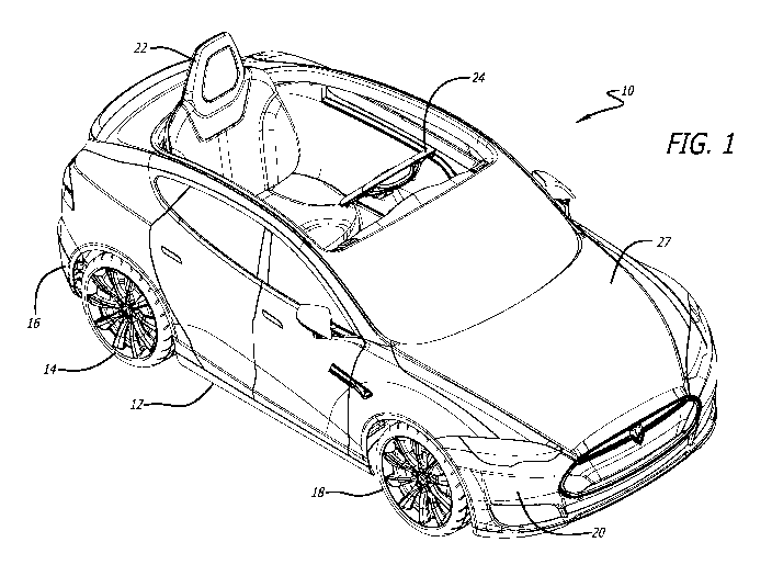
[0041] FIG. I is a front perspective view of a battery-powered vehicle
according to one
embodiment.
[0042] FIG. 2 is a rear perspective view of the battery-powered vehicle of
FIG. 1.
[0043] FIG. 3 is a partial perspective view of one embodiment of a charging
system for a
battery-powered vehicle, with the charger connected to the remote charging
port.
[0044] FIG. 4 is a partial perspective view of one embodiment of a charging
system for a
battery-powered vehicle, with the charger disconnected from the remote
charging port.
[0045] FIG. 5 is a top partial perspective view of a battery-powered
vehicle according to one
embodiment, with the trunk opened to show the battery and the high/low speed
selector switch.
[0046] FIG. 6 is a top partial perspective view of the battery-powered
vehicle of FIG. 5, with
the battery removed from the battery port.
100471 FIG. 7 is a top view of the battery-powered vehicle of FIG. 1.
[0048] FIG. 8 is an exploded top perspective view of one embodiment of a
forward/reverse
switch assembly for a battery-powered vehicle.
[0049] FIG. 9 is an exploded bottom perspective view of the forward/reverse
switch
assembly of FIG. 8.
100501 FIG. 10 is an assembled perspective view of the forward/reverse
switch assembly of
FIGS. 8 and 9.
CA 03014278 2018-08-10
WO 2017/139549 PCT/US2017/017333
[0051] FIG. Ii is a schematic of a forward/reverse switching system
connected to a power
source and motors of a battery-powered vehicle, with the vehicle configured in
the forward
direction and in the high gear, according to one embodiment.
[0052] FIG. 12 is a schematic of a forward/reverse switching system
connected to a power
source and motors of a battery-powered vehicle, with the vehicle configured in
the forward
direction and in the low gear, according to one embodiment.
[0053] FIG. 13A is a schematic of a forward/reverse switching system
connected to a power
source and motors of a battery-powered vehicle, with the vehicle configured in
the reverse
direction and in the high gear, according to one embodiment.
[0054] FIG. 13B is schematic of a forward/reverse switching system
connected to a power
source and motors of a battery-powered vehicle, with the vehicle configured in
the reverse
direction and in the high gear, according to another embodiment.
100551 FIG. 13C is a schematic of a forward/reverse switching system
connected to a power
source and motors of a battery-powered vehicle, with the vehicle configured in
the reverse
direction and in the low gear, according to one embodiment.
[0056] FIG. 14 is a schematic showing a charging system and a dashboard
electronics system
for a battery-powered vehicle according to one embodiment, with the battery
disconnected from
the battery dock and the charger disconnected from the charging dock.
[0057] FIG. 15 is a schematic showing the charging system of FIG. 14,
without the
dashboard electronics system, with the battery connected to the battery dock
and the charger
connected to the charging dock.
[0058] FIG. 16 is a schematic showing the charging system of FIG. 14,
without the
dashboard electronics system, with the battery disconnected from the battery
dock and the
charger disconnected from the charging dock.
[0059] FIG. 17 is a schematic showing a communication system for a charging
system for a
battery-powered vehicle, according to one embodiment.
11
CA 03014278 2018-08-10
WO 2017/139549 PCT/US2017/017333
[0060] FIG. 18 is a flow chart of the logic for a wake-up function for
electronics for a
battery-powered vehicle, according to one embodiment.
DETAILED DESCRIPTION
[0061] While the ride-on vehicle discussed herein is susceptible of
embodiments in many
different forms, there is shown in the drawings, and will herein be described
in detail, preferred
embodiments with the understanding that the present description is to be
considered as an
exemplification of the principles of the ride-on vehicle and are not intended
to limit the broad
aspects of the disclosure to the embodiments illustrated.
100621 The battery-powered vehicle is a ride-on vehicle that is preferably
used by children
and adolescents, but in alternate embodiments may be used by larger
individuals, such as adults.
Referring now to FIGS. 1, 2 and 7, one embodiment the overall battery-powered
vehicle 10 is
shown. The battery-powered vehicle 10 may include a frame 12 supported by a
plurality of
wheels, including in one embodiment, a pair of rear wheels 14 at the rearward
portion 16 of the
frame 12, and a pair of front wheels 18 at the forward portion 20 of the frame
12. Additionally,
the vehicle 10 has a vehicle body 27 supported by the wheels and the frame.
The vehicle 10 also
preferably includes a seat 22 to support the rider, a steering wheel 24
operably connected to the
front wheels 18 via a steering column 26 to assist in steering the vehicle 10,
an accelerator 28,
and one or more motors 38. In a preferred embodiment a pair of motors 38 is
provided. In one
embodiment, the motor(s) are electrically connected to the accelerator 28, and
preferably to an
accelerator switch controller 29. In one embodiment, a first motor 38 is
provided for a first one
of the rear wheels 14 and a second motor 38 is provided for a second of the
rear wheels 14.
Alternately, only one motor may be provided and it may drive two or more
wheels, or alternately
yet, only one motor may be provided and it may drive only one wheel of the
vehicle. The motors
38 may be connected to the frame 12 and underneath the seat 22, as shown in
FIG. 7, and also
are mechanically connected to the wheel(s). As explained herein, in one
embodiment when the
user depresses the accelerator 28, a battery 40, which is electrically
connected to the motor(s),
supplies current to the motor(s) 38 to have the motor(s) 38 rotate the rear
wheels 14 to drive the
vehicle 10. Additionally, after the accelerator 28 is depressed the battery 40
will also supply
current to the various electronics on the vehicle 10 for a period of time. As
further discussed
12
CA 03014278 2018-08-10
WO 2017/139549 PCT/US2017/017333
herein as well, the vehicle 10 may be driven in both the forward mode to
propel the vehicle 10
forward, and in the reverse mode to propel the vehicle 10 backwards. In
various embodiments,
the battery-powered vehicle 10 may also have a charging system 30, as shown in
FIGS. 3-6 and
14-16, a forward/reverse switching system 32, as shown in FIGS. 2 and 8-13, a
motor disabling
system 34, as shown in FIG. 17, and an electronics wakeup system 36, as shown
schematically in
FIGS. 14 and 18.
[0063] Referring now to FIGS. 14-17, in one embodiment, aspects of the
charging system 30
for the battery-powered vehicle 10 comprise one or more of the battery 40, a
battery dock 42, a
remote charging dock 44, and a charger 46.
[0064] In one embodiment, each of the charger 46, the remote charging dock
44, the battery
dock 42 and the battery 40 preferably has a circuit board or controller in
electrical
communication therewith that receives data, transmits data, calculates data
and/or makes
calculations and decisions using the data, and receives and transmits
current/power. For
example, in one embodiment, a remote charging dock circuit board 45, also
referred to as a first
controller 45, is in electrical communication with the remote charging dock
44. Similarly, in one
embodiment a battery dock circuit board 43, also referred to as a second
controller 43, is in
electrical communication with the battery dock 42. Further, in one embodiment,
the charger 46
has a charger circuit board 47, which is also referred to as a third
controller 47. And, in one
embodiment, the battery plug 56 of the battery 40 has a battery or battery
plug circuit board 57,
also referred to as a fourth controller 57. In one embodiment the pedal switch
28 has a pedal
switch circuit board 29, which is also referred to as a pedal switch
controller 29. Finally, the
electronics in the cockpit of the vehicle 10, such as on the vehicle's
dashboard or other locations,
also may have an electronics controller 95.
[0065] The battery 40 is preferably a removable and rechargeable battery 40
having a battery
plug 56 that has a third set of terminals 58, also referred to herein as
battery terminals 58, in a
terminal arrangement. In one embodiment the terminal arrangement of the third
set of terminals
58 of the battery plug 56 is that of a male terminal arrangement. The battery
40 also has a
battery circuit board 57, also referred to as a fourth controller 57. The
fourth controller 57
communicates with one of the second controller in the battery dock when the
battery is
13
CA 03014278 2018-08-10
WO 2017/139549 PCT/US2017/017333
connected to the battery dock, and the third controller in the charger.
Further, when the battery is
connected directly to the charger, the fourth controller communicates with the
third controller in
the charger via communication line 80. The third controller in the charger
monitors battery
parameters based on data transmitted from the fourth controller to the third
controller through the
communication line.
100661 In one embodiment the battery 40 is comprised of a series of
rechargeable battery
cells. Further, in one embodiment the battery 40 may be a rechargeable lithium
ion battery,
however other types of batteries, including other types of rechargeable
batteries, may be
provided. In one embodiment, the battery 40 has a first end 41a and a second
end 41b. A handle
41c may be provided and located at the second end 41b of the battery 40. In a
preferred
embodiment, the battery terminals 58 are provided at the first end 41a of the
battery 40. As
explained herein, the battery 40 is configured to be charged in the battery
port 72 when (a) the
battery 40 is positioned in the battery port 72 and the battery terminals 58
electrically and
mechanically mate with the battery dock terminals 54, and (b) when the charger
terminals 50 of
the charger 46 are connected to the remote charging terminals 62 of the remote
charging dock
44. The battery 40 is also configured to be charged remote from the vehicle 10
when the battery
is removed from the battery port 72 and the battery terminals 58 electrically
and mechanically
mate with the charger terminals 50 for charging outside the battery port 72.
100671 As shown in FIG. 14, in one embodiment the terminal arrangement of
the third set of
terminals 58 of the battery plug 56 of the battery 40 is that of a male
terminal arrangement.
Similarly, in one embodiment the remote charging dock 44 has a remote charging
plug 60 that
has a fourth set of terminals 62 in a terminal arrangement. The fourth set of
terminals 62 are also
referred to as the remote charging terminals 62. In one embodiment the
terminal arrangement of
fourth set of terminals 62 of the remote charging plug 60 is also that of a
male terminal
arrangement. Accordingly, the terminal arrangement of the third set of
terminals 58 of the
battery plug 56 is preferably the same as the terminal arrangement on the
fourth set of terminals
62 of the remote charging plug 60.
100681 Also shown best in FIG. 14, in one embodiment the battery dock 42
has a battery
dock plug 52 that has a second set of terminals 54 in a terminal arrangement.
In one
14
CA 03014278 2018-08-10
WO 2017/139549 PCT/US2017/017333
embodiment the terminal arrangement of the terminals 54 of the battery dock
plug 52 is that of a
female terminal arrangement. Similarly, the charger 46 of the charging system
30 preferably has
a charger plug 48 and associated charger terminals 50, referred to as a first
set of terminals 50,
which are in a terminal arrangement. In one embodiment the terminal
arrangement of the first
set of terminals 50 on the charger plug 48 is that of a female terminal
arrangement. Preferably,
the terminal arrangement of the second set of terminals 54 on the battery dock
plug 52, also
referred to as the battery dock terminals 54, is the same as the terminal
arrangement of the first
set of terminals 50 on the charger plug.
[0069] Accordingly, in one embodiment, the charger terminals 50 and the
battery dock
terminals 54 have a first terminal configuration, and the remote charging
terminals 62 and the
battery terminals 58 have a second terminal configuration. The first terminal
configuration is
preferably different from the second terminal configuration, and most
preferably the terminals of
the first terminal configuration are adapted to mate with the terminals of the
second terminal
configuration.
[0070] As shown in the schematic of FIG. 15, the battery 40 for the battery-
powered vehicle
may be charged while the battery 40 remains connected to the vehicle 10 and
without
removing the battery 40 from the vehicle 10. In one embodiment, the battery 40
is housed in a
battery port 72 that may extend into the vehicle body 27, such as into the
trunk 70 of the vehicle,
as shown in FIG. 5, and in such an embodiment the battery port 72 is
accessible by lifting the
trunk hatch 68 of the vehicle 10. The battery port 72 preferably includes the
battery dock 42 and
the battery dock terminals 54. In such an embodiment, when the battery 40 is
inserted into the
battery housing or battery port 72 in the trunk 70 of the vehicle 10, the
third set of terminals 58
on the battery plug 56 of the battery mate with the second set of terminals 54
on the battery dock
plug 52 of the battery dock 42. Accordingly, in one embodiment, when the
battery 40 is inserted
into the battery port 72, the terminals 58 of the battery 40 electrically
connect to the terminals 54
on the battery dock 42.
[0071] In one embodiment the remote charging dock 44 is adjacent an
exterior of the vehicle
body 27, and the remote charging dock 44 has a remote charging plug 60. As
shown in FIGS. 3
and 4, preferably the remote charging plug 60 of the remote charging dock 44
is accessible from
I/
CA 03014278 2018-08-10
WO 2017/139549 PCT/US2017/017333
the outside of the vehicle 10, and in one embodiment preferably is positioned
behind an openable
door portion 76 of the rear tail light 78. Accordingly, a user can charge the
battery 40 by
plugging one end of the charger 46 into a wall outlet and the other end of the
charger 46 into the
remote charging dock 44. The remote charging dock 44 has a remote charging
dock circuit
board 45, also referred to as a first controller 45. Similarly, the charger 46
has a third controller
47, as explained above. The third controller 47 of the charger 46 is
electrically connected to the
first controller 45 of the remote charging dock 44 when the charger 46 is
connected or plugged
into the remote charging dock.
100721 In a preferred embodiment the remote charging dock 44 is
electrically connected to
the battery dock 42. In one embodiment, the first wiring harness 74
electrically connects the
remote charging dock 44 with the battery dock 42. In one embodiment, the first
wiring harness
74 includes a communication line 82 and power lines 83. Specifically, current
is capable of
flowing from the remote charging dock 44 to the battery dock 42 through the
power lines 83 in
the first wiring harness 74 connecting the remote charging dock 44 with the
battery dock 42.
Similarly, data is able to be transmitted between the first controller 45
(identified herein) in the
remote charging dock 44 and the second controller 43 (identified herein) in
the battery dock,
through the first communication line 82 in the first wiring harness 74.
100731 A communication line 80 is provided in the charger 46 between the
charger circuit
board and the terminals in the charger plug, and a separate communication line
82 is provided in
the wiring harness 74 between the circuit board in the remote charging dock 44
and the battery
dock 42. The communication lines 82 provide for transmitting data between the
charger 46 and
the battery 40. A communication protocol allows the charger 46 to communicate
bi-directionally
with the battery 40 in both the remote charging mode of FIG. 15 as well as the
direct charging
mode of FIG. 16. The charger 46 continually monitors a variety of parameters
such as battery
voltage, cell voltage, cell imbalance, charge time, etc., to provide for a
safe and complete
charging of the battery cells during charging. The first and second
communication lines 80, 82
allow the fourth controller 57 to communicate with the second controller 43 in
the battery dock
42 and the third controller 47 in the charger 46 when the battery 40 is
connected to the battery
dock 42.
16
IV
CA 03014278 2018-08-10
WO 2017/139549 PCT/US2017/017333
[0074] Further, in a preferred embodiment the accelerator/pedal switch 28,
and more
specifically the accelerator controller 29, also referred to as the pedal
switch controller 29, is
electrically connected to the battery dock 42, and more specifically the
battery dock controller
43, via a second wiring harness 75. In one embodiment, the second wiring
harness 75
electrically connects the accelerator controller 29 with the second controller
43 in the battery
dock 42. In one embodiment, the second wiring harness 75 includes a
communication line 92
and power lines 93. Specifically, current/power is capable of flowing from the
battery dock 42
to the accelerator/pedal switch controller 29 through the power lines 93 in
the second wiring
harness 75 connecting the accelerator/pedal switch controller 29 with the
battery dock 42.
Similarly, data is able to be transmitted between the accelerator/pedal switch
controller 29 and
the second controller 43 in the battery dock, through the communication line
92 in the second
wiring harness 75. Further, current/power is also able to flow from the
accelerator/pedal switch
controller 29 and the electronics controller 95 through power lines 97.
[0075] In one embodiment, as shown in FIG. 15, current from a standard
house outlet flows
(i) through the charger 46, (ii) out the first set of terminals 50 in the
charger plug 48, (iii) into the
fourth set of terminals 62 in the remote charging plug 60, (iv) through the
remote charging dock
44, (v) through the wiring harness 74, (vi) into the battery dock 42, (vii)
into the battery dock
plug 52, (viii) through the second set of terminals 54 in the battery dock
plug 52, (ix) into the
third set of terminals 58 in the battery plug 56, and (x) into the cells of
the battery 40.
[0076] Alternately, as shown in FIGS. 6 and 16, the battery 40 for the
battery-powered
vehicle 10 may be charged by removing the battery 40 from the battery port 72
in the vehicle 10
and connecting the battery 40 directly to the charger 46. Accordingly, a user
can charge the
battery 40 by plugging one end of the charger 46 into a wall outlet and the
other end of the
charger 46 directly into the battery 40. In one embodiment, current from a
standard house outlet
flows (i) through the charger 46, (ii) out the first set of terminals 50 in
the charger plug 48, (iii)
into the third set of terminals 58 in the battery plug 56, and (iv) into the
cells of the battery 40.
Such alternate arrangements are possible because both the terminals of the
battery plug and the
remote charging plug have a similar terminal arrangement (a first terminal
arrangement), and
both the terminals of the charger plug and the terminals of the battery dock
plug have a similar
terminal arrangement (a second terminal arrangement), and the terminals of the
first terminal
17
CA 03014278 2018-08-10
WO 2017/139549 PCT/US2017/017333
arrangement are able to physically/mechanically and electrically mate with the
terminals of the
second terminal arrangement.
100771 Referring to FIG. 17, in one embodiment the battery-powered vehicle
10 has a motor
disable system 34. This system is utilized when the battery 40 is connected to
the battery port 72
in the trunk 70 of the vehicle 10, and the battery 40 is being charged via the
charger 46 through
the remote charging dock 44, or alternately merely when the charger 46 is
connected to the
remote charging dock 44 of the vehicle 10. Because in this instance the
vehicle 10 is essentially
connected through the charger 46 to a power source, it would be undesirable
for the motors 38 of
the vehicle 10 to be operable to move the vehicle 10. Accordingly, the motor
disabling system
34 is utilized. In one embodiment, the motor disabling system 34 includes a
communication
protocol that prevents the release of current from the battery 40 to the
motors 38 when the
charger 46 is connected to the remote charging dock 44. As shown in FIG. 17,
and as explained
herein, accelerator switch 28 has a circuit board/controller 29 that is
electrically connected to the
circuit board/controller 43 of the battery dock 42 via a communication line
92. The
communication protocol of the motor disabling system 34 informs the controller
29 in the
accelerator switch 28 as to whether the charger 46 is connected to the remote
charging dock 44.
If the charger 46 is detected as being connected to the remote charging dock
44, the controller 29
of the accelerate switch 28 or the second controller 43 in the battery dock 42
prevents the release
of current to the motors 38, thereby not allowing the motors 38 to be operable
to move the
vehicle 10.
[0078] The electronics wakeup system 36 for the vehicle 10 is shown
schematically in FIGS.
14 and 18. The electronics wakeup system 36 generally allows a user to have
the vehicle 10
power up various electronic components in the vehicle 10 by depressing a
switch, such as the
accelerator pedal switch 28, and for the electronic components to remain on
for a period of time
after the switch (e.g., the accelerator pedal switch 28) was last depressed.
The shape or form of
the accelerator switch/pedal switch is irrelevant and may take any shape or
form, and may be
hand operated, foot operated, or operated by other means. Various electronic
components on the
vehicle 10 may include a music player, such as a MP3 music player, speakers, a
horn, lights,
instrument panel, etc. The electronic components receive power from the
vehicle's battery 40.
18
I r
CA 03014278 2018-08-10
WO 2017/139549 PCT/US2017/017333
[0079] In one embodiment, the electronics wakeup system includes the
accelerator switch
28, an accelerator switch controller 29, and the second wiring harness 75. A
power line 97
connecting the electronics controller 95 is also required. In one embodiment,
the power line 97
connects the electronics controller 95 with the accelerator controller 29 to
allow current to flow
between the accelerator controller 29 and the electronics controller 95. The
electronics controller
95 may also be referred to as a dashboard controller 95 because several of the
electrical
components to that are controlled by the electronics controller 95 and which
receive power from
the electronics controller 95 will be located in the vehicle's dashboard. The
electronics
controller 95 is in electrical communication with the accelerator controller
29 and the electrical
components. In one embodiment, by operating the switch (e.g., accelerator or
pedal switch 28)
current is provided from the battery 40 to the electronics controller 95. In
one embodiment a
circuit is closed to provide power from the battery 40 to the electronics
controller 95 and the
electronic devices through the power lines 97 from the accelerator controller
29 to the electronic
controller 95. In one embodiment, as shown in step 100 in FIG. 18, when the
vehicle 10 is idle
or otherwise in standby mode, the circuit between the electronics on the
vehicle 10 and the
battery 40 is open and thus no current from the battery 40 reaches the
electronic controller 95.
However, as shown in step 102 in FIG. 18, when the user depresses the
accelerator pedal 28 in
the vehicle 10, the circuit between the electronic controller 95 on the
vehicle 10 and the battery
40 closes, thereby "waking up" the vehicle 10 and allowing current to flow
from the battery 40 to
the electronics. At that point all electronics in the vehicle 10 will be
operable as shown in step
104.
[0080] In step 106, a processor or controller of the vehicle 10, such as a
controller having a
timer, will monitor when the timing of when the accelerator switch is 28
depressed and how
much time has elapsed since the switch was last depressed, and will keep the
circuit closed
between the battery 40 and the electronics for a period of time, such as ten
minutes, after the
accelerator switch 28 is depressed. In one embodiment, the accelerator
controller 29 includes the
timer. In an alternate embodiment the timer is provided in either the battery
dock controller 43
or the electronics controller 95. In one embodiment, the timer calculates the
time between
actuations of the accelerator switch 28, and when the time between actuations
of the accelerator
switch 28 is greater than an electronics timer threshold, e.g., ten minutes,
one of the accelerator
19
CA 03014278 2018-08-10
WO 2017/139549 PCT/US2017/017333
controller 29, the battery dock controller 43 or the electronics controller 95
prevents the release
of current to the electronics controller 95 until the accelerator switch 28 is
actuated again. As
shown in step 108, after the defined period of time, which in one embodiment
is ten minutes, in
one embodiment the vehicle's controller/processor will open the circuit
between the battery 40
and the electronics, or otherwise prevent power to flow to the vehicle's
electronics, thereby
removing the supply of current from the battery 40 to the vehicle's
electronics and essentially
powering down all electronics in the vehicle 10. To once again power up the
electronics, the
user will have to depress or actuate the switch 28 as shown in step 102.
Accordingly, no on/off
switch is necessary for each electronic device on the vehicle 10, and no
on/off switch is
necessary to power up the vehicle 10 to either operate an electronic device on
the vehicle 10 or to
drive the vehicle 10. Preferably, a voltage regulator (not shown) is provided
to step down the
voltage from the accelerator controller 29 to the electronics controller 95.
hi one embodiment
the voltage is stepped down from approximately 14.4 volts to about 4 volts.
100811 As discussed above, the vehicle 10 may be driven in both the forward
mode to propel
the vehicle 10 forward, and in the reverse mode to propel the vehicle 10
backwards. In one
embodiment, to assist in controlling whether the vehicle 10 is able to move in
the forward mode
or in the reverse mode and to determine how fast the vehicle 10 may traverse,
the vehicle 10 may
have a forward/reverse switching system 32, as shown in FIGS. 2, 7-13.
Referring to these
figures, in one embodiment the forward/reverse switching system 32 may
comprise one or more
of a forward/reverse switch assembly 120 (also referred to as a direction
switch assembly 120), a
speed control switch 122, the battery 40 and the motors 38. In one embodiment
the
forward/reverse switch assembly 120 includes, among other components described
below, a
toggle switch with two positions, a forward position and a reverse position.
Alternately, the
forward/reverse switch assembly 120 includes two separate buttons, a forward
button 126 and a
reverse button 128. Additionally, in one embodiment the speed control switch
122 includes a
toggle switch with two positions, a high speed position and a low speed
position, or alternately
separate buttons. In one embodiment the direction switch assembly 120 is
electrically connected
between the battery 40 and the motor 38. The speed switch assembly 122 is
preferably
electrically connected between the direction switch assembly 120 and the
motor(s) 38. The
speed switch is preferably separate from the direction switch.
CA 03014278 2018-08-10
WO 2017/139549 PCT/US2017/017333
100821 The vehicle 10 may be operated in a high speed mode and a low speed
mode.
However, in one embodiment the vehicle may not be operated in the high speed
when in the
reverse mode, regardless of whether the speed control switch 122 is set to the
high speed mode.
Put another way, when the reverse button of the direction switch assembly is
actuated it removes
control of a speed of the motor from the speed switch, and when the forward
button of the
direction switch assembly is actuated it causes the speed switch to control
the speed of the motor.
Accordingly, in one embodiment the vehicle may be operated in the high speed
or the low speed
when in the forward mode, but only in the low speed when in the reverse mode.
In a preferred
embodiment, the vehicle may be in high speed when the reverse direction is
selected, but the
vehicle will automatically place the vehicle in low speed for reversing. If
the forward direction
is selected next, the vehicle will once again convert to high speed
automatically unless the low
speed has been selected. In one embodiment where the vehicle 10 has two motors
38, when the
vehicle 10 is in the high speed mode the vehicle 10 provides approximately
14.4 volts from the
battery 40 to each motor 38, but when the vehicle 10 is in the low speed mode
the vehicle 10
only provides approximately 7.2 volts from the battery 40 to each motor 38
(i.e., 14.4 volts in
series to the two motors) to reduce the operating speed of each motor 38 in
the low speed mode.
If only one motor is utilized the system will provide less voltage to the one
motor in the low
speed mode.
[0083] In one embodiment the direction switch assembly 120 and the speed
control switch
122 are provided in separate locations on the vehicle 10. For example, as
shown in FIGS. 2 and
7, the forward/reverse switch assembly 120 may be provided in the cockpit of
the vehicle, such
as on the dashboard or instrument panel 124 of the vehicle 10. Similarly, in
one embodiment the
speed control switch 122 may be provided at a separate location from the
forward/reverse switch
assembly 120 and outside the cockpit of the vehicle 10, such as the trunk 70
of the vehicle 10. In
such a configuration, the user is able to readily control whether the vehicle
10 is in the forward
mode or the reverse mode by operating the forward/reverse switch assembly 120
located in the
dashboard of the vehicle 10, while a parent or other supervisor is able to
control whether the
vehicle 10 is in the high speed or the low speed because the speed control
switch 122 is in the
trunk 70 of the vehicle 10 and is generally not accessible by a rider seated
in the seat 22 of the
vehicle 10. In one embodiment, the direction switch assembly is proximal the
driver's seat in the
21
CA 03014278 2018-08-10
WO 2017/139549 PCT/US2017/017333
vehicle body, and the speed switch is distal the driver's seat and generally
not accessible by a
rider seated in the driver's seat.
100841 One embodiment of the forward/reverse switch assembly 120 is shown
in FIGS. 8-10.
As shown, the forward/reverse switch assembly 120 may comprise a forward
button 126, a
reverse button 128, a pivotable rocker plate 130, a forward/reverse switch 132
(also referred to as
a first switch 132), which may be a toggle switch such as, for example, a two
position toggle
switch, a second switch 134, which also may be a toggle switch such as, for
example, a two
position toggle switch, a switch housing 136 to pivotally retain the rocker
plate 130 and also to
retain the forward/reverse switch 132 and the second switch 134, and a wiring
harness plug 138
to receive a wiring harness to connect, preferably separably, into the
forward/reverse switch 132
and the second switch 134.
[0085] The rocker plate 130 is provided between the two buttons (i.e., the
forward button
126 and the reverse button 128) and the two switches (i.e., the first switch
132 and the second
switch134) so that when one button is depressed, which could be either the
forward button 126
or the reverse button 128, both switches 132 and 134 are operated
simultaneously. In one
embodiment as best shown in FIGS. 8-10, the forward button 126 has a forward
button arm 140
on one side of the forward button 126, and the reverse button 128 has a
reverse button arm 142
that is on the opposite side of the reverse button 128. As such, when the
forward button 126 is
depressed the forward button arm 140 engages a first side 144 of the rocker
plate 130 to pivot the
rocker plate 130 to a first orientation, and when the reverse button 128 is
depressed the reverse
button arm 142 engages an opposite second side 146 of the rocker plate 130 to
pivot the rocker
plate 130 to a second orientation.
[0086] In one embodiment, the first switch 132 determines the polarity of
the first switch 132
which determines the polarity of the current provided to the motors 38 to
place the vehicle 10
either in the forward mode or the reverse mode. For example, when the current
is provided in
one polarity the motors spin in one direction, and when the polarity of the
current is reversed the
motors will spin in the opposite direction, one direction being the forward
direction and the other
direction being the reverse direction. Put another way, when the first switch
is in a first position
the current provided to the motor has a first polarity, and when the first
switch is in a second
position the current provided to the motor has a second polarity opposite the
first polarity. And,
in one embodiment, the second switch 134, sometimes referred to as the reverse
switch,
22
CA 03014278 2018-08-10
WO 2017/139549 PCT/US2017/017333
determines the polarity of the second switch 134 to either allow current to
flow through the speed
control switch 122 (e.g., when the forward/reverse switch 132 is in the
forward mode) or to
bypass the speed control switch 122 (e.g., when the forward/reverse switch 132
is in the reverse
mode) to require voltage to be sent to the motors 38 in series, thereby, in
one embodiment, only
providing approximately 7.2 volts per motor 38. In a preferred embodiment the
first switch 132,
the second switch 124 and the speed control switch 122 are each 6-pin
switches, and by toggling
the switches the middle two pins will either be connected with the first (or
top) two pins, or last
(or bottom) two pins as shown in FIGS. 11-13C. Accordingly, in one embodiment,
a voltage is
provided to the motors in parallel when the forward button is actuated and
when the speed switch
is in the high speed setting; a voltage is provided to the motors in series
when the forward button
is actuated and when the speed switch is in the low speed setting; and, a
voltage is provided to
the motors in series when reverse button is actuated regardless of the setting
of the speed switch.
100871 As shown in FIGS. 11 and 12, the forward button 126 is depressed. In
this first
orientation of the rocker plate 130 (i.e., when the forward button 126 is
depressed) both the
forward/reverse switch 132 and the second switch 134 are operated or toggled
to a first position
together. In one embodiment when the forward/reverse switch 132 is in the
first position that
switch is in the forward mode (e.g., positive polarity of the forward/reverse
switch 132), and
when the second switch 134 is in the first position the polarity of that
switch is also positive such
that an additional loop will be created to pass current through the speed
control switch 122 to
determine whether the motors 38 will be in high speed mode, as shown in FIG.
11, whereby
voltage will be sent from the battery 40 to the motors 38 in parallel (i.e.,
approximately 14.4
volts per motor in one embodiment) or the low speed mode, as shown in FIG. 12,
whereby
voltage will be sent from the battery 40 to the motors 38 in series (i.e.,
approximately 7.2 volts
per motor in one embodiment). As shown in FIGS. 11 and 12, in the forward mode
the middle
two pins of the first switch 132 will be electrically connected with the top
two pins of the first
switch 132. Further, in the high speed the middle two pins of the speed
control switch 122 will
be connected to the top two pins (shown in dashed line in FIG. 11), whereas in
the low speed the
middle two pins of the speed control switch 122 will be connected to the
bottom two pins (shown
in dashed line in FIG. 12). By joining the bottom 4 pins in the speed control
switch 122 a loop is
created that places the motors in series. The arrows in the FIGS. 11 and 12
(as well as FIGS.
13A-13C) show the direction of current flow, and the darker lines in these
figures shown the
23
If
CA 03014278 2018-08-10
WO 2017/139549 PCT/US2017/017333
flow of current (other than to dead ends). Accordingly, both ground and
voltage are separately
provided to the two motors (in parallel) in the circuit of FIG. 11, whereas
ground and voltage are
provided in series to the two motors in the circuit of FIG. 12 (shown
schematically in FIG. 12 as
a dashed line between motors M2 and M3).
[0088] Referring to FIGS. 13A-13C, schematics are provided showing the flow
of current
when the reverse button 128 is depressed on the first switch 120. Accordingly,
in the second
orientation of the rocker plate 130 (i.e., when the reverse button 128 is
depressed) both the
forward/reverse switch 132 and the second switch 134 are operated or toggled
to a second
position together. In one embodiment when the forward/reverse switch 132 is in
the second
position that switch is in the reverse mode (e.g., negative polarity of the
forward/reverse switch
132), and when the second switch 134 is in the second position the polarity of
that switch is also
negative. However, as shown in FIGS. 13A-13C, when the polarity of the second
switch 134 is
reversed (e.g., in this embodiment negative) an additional loop is not created
to pass current to
the motors in parallel. Instead, the current always flows to connect the two
motors 38 in series,
which is the low speed. In the low speed approximately 7.2 volts are provided
to each motor 38.
Accordingly, in the reverse mode the vehicle 10 will always be in the low
speed. Specifically,
when the reverse button 128 is depressed and the speed control switch 122 is
in the high mode,
two different loops are created as shown in FIGS. 13A and 13B, both of which,
however, place
the motors in series as shown schematically by the dashed line between the
motors M2 and M3.
Additionally, as shown in FIG. 13C, when the reverse button 128 is depressed
and the speed
control switch 122 is in the low mode, a similar loop to that created in the
forward/low speed of
FIG. 12 is created as shown in FIG. 13C, which places the motors in series as
shown
schematically by the dashed line between the motors M2 and M3. The main
difference between
the schematic of FIG. 12 and the schematic of FIG. 13C is that the polarity of
the current to the
motors is reverse in the two figures so that in FIG. 12 the motors rotate in
the forward direction,
and in FIG. 13C the motors rotate in the opposite or reverse direction.
[0089] Several alternative embodiments and examples have been described and
illustrated
herein. A person of ordinary skill in the art would appreciate the features of
the individual
embodiments, and the possible combinations and variations of the components. A
person of
ordinary skill in the art would further appreciate that any of the embodiments
could be provided
in any combination with the other embodiments disclosed herein. Additionally,
the terms "first,"
24
CA 03014278 2018-08-10
WO 2017/139549 PCT/US2017/017333
"second," "third," and "fourth" as used herein are intended for illustrative
purposes only and do
not limit the embodiments in any way. Further, the term "plurality" as used
herein indicates any
number greater than one, either disjunctively or conjunctively, as necessary,
up to an infinite
number. Additionally, the term "having" as used herein in both the disclosure
and claims, is
utilized in an open-ended manner.
[0090] It will be understood that the disclosed embodiments may be embodied
in other
specific forms without departing from the spirit or central characteristics
thereof. The present
examples and embodiments, therefore, are to be considered in all respects as
illustrative and not
restrictive, and the disclosed embodiments are not to be limited to the
details given herein.
Accordingly, while the specific embodiments have been illustrated and
described, numerous
modifications come to mind without significantly departing from the spirit of
the disclosure and
the scope of protection is only limited by the scope of the accompanying
Claims.