Note: Descriptions are shown in the official language in which they were submitted.
Mesh Fitting Algorithm
COPYRIGHT NOTICE
[0001] A portion of the disclosure of this patent document contains mate-
rial that is subject to copyright protection. The copyright owner has no
objection
to the facsimile reproduction by anyone of the patent document or the patent
disclosure, as it appears in the Patent and Trademark Office patent file or
rec-
ords, but otherwise reserves all copyright rights whatsoever.
BACKGROUND OF THE INVENTION
1. Field of the Invention.
[0002] This invention relates to image data processing. More particular-
ly, this invention relates to modeling and registration of 3-dimensional
images of
the heart.
2. Description of the Related Art.
[0003] Medical catheterizations are routinely carried out today, for ex-
ample, in cases of cardiac arrhythmias, such as atrial fibrillation, which
occur
when regions of cardiac tissue abnormally conduct electric signals to adjacent
tissue, thereby disrupting the normal cardiac cycle and causing asynchronous
rhythm. Procedures for treating arrhythmia include surgically disrupting the
origin of the signals causing the arrhythmia, as well as disrupting the
conducting
pathway for such signals. By selectively ablating cardiac tissue by
application of
energy, e.g., radiofrequency energy via a catheter, it is sometimes possible
to
cease or modify the propagation of unwanted electrical signals from one
portion
of the heart to another. The ablation process destroys the unwanted electrical
pathways by formation of non-conducting lesions. It is desirable in such proce-
dures to provide a convenient representations of the cardiac anatomy to the op-
erator.
[0004] Catheters containing position sensors may be used to determine
the trajectory of points on the cardiac surface. These trajectories may be
used to
infer motion characteristics such as the contractility of the tissue. As
disclosed in
U.S. Pat. No. 5,738,096, issued to Ben Haim, which is incorporated herein by
ref-
1 of 22
CA 3015087 2018-08-23
erence, maps depicting such motion characteristics may be constructed when
the trajectory information is sampled at a sufficient number of points in the
heart.
[0005] Electrical activity at a point in the heart is typically measured by
advancing a catheter containing an electrical sensor at or near its distal tip
to
that point in the heart, contacting the tissue with the sensor and acquiring
data at
that point. One drawback with mapping a cardiac chamber using a catheter con-
taining only a single, distal tip electrode is the long period of time
required to
accumulate data on a point-by-point basis over the requisite number of points
required for a detailed map of the chamber as a whole. Accordingly, multiple-
electrode catheters have been developed to simultaneously measure electrical
activity, such as local activation times (LAI) at multiple sampled points in
the
heart chamber.
[0006] For example, commonly assigned U.S. Patent Application Publica-
tion No. 2017/0103570 to Zar et al., which is herein incorporated by
reference,
discloses 3-dimensional cardiac reconstruction is carried out by catheterizing
a
heart using a probe with a mapping electrode, and acquiring electrical data
from respective locations in regions of interest in the heart, representing
the lo-
cations of the electrical data as a point cloud, reconstructing a model of the
heart
from the point cloud, applying a set of filters to the model to produce a
filtered
volume, segmenting the filtered volume to define components of the heart, and
reporting the segmented filtered volume.
[0007] U.S. Patent No. 8,428,700 to Harley et al., proposes generating an
electroanatomic representation of a patient's heart based on the signals meas-
ured at the electrodes and information about the positions of the electrodes.
The
method includes performing a catheter registration procedure with other imag-
ing modalities, such as MRI, annotating the measured signals, and adjusting
the
annotations for other measured signals in spatial proximity to the specified
measured signal.
SUMMARY OF THE INVENTION
[0008] A typical catheterization session involves registration of a scanned
CT/MRI image with a 3-dimensional electroanatomic map. However, after regis-
tration there are still differences between the CT/MRI image and the real time
2 of 22
CA 3015087 2018-08-23
anatomy determined in a current position map. During the procedure real-time
catheter positions are established, and it is verified that the catheter
electrodes
are in contact with the heart wall, for example by a force threshold
measurement
or by tissue proximity indications. The current position map is registered
with a
CT/MRI image.
[0009] A mesh fitting algorithm to identify and resolve the differences in
real-time. A 3-dimensional matrix is constructed to model the current position
map. Points on the matrix are then adjusted to more closely approximate points
on the current position map.
[0010] There is provided according to embodiments of the invention a
method, which is carried out by inserting a multi-electrode probe into a
heart,
constructing a position map of the electrodes, and simulating a 3-dimensional
surface of the heart. The method is further carried out by placing the
position
map in registration with an acquired image of the heart, constructing, based
on
the position map, a mesh that models the 3-dimensional surface of the heart,
and
adjusting positions of vertices of the mesh relative to mapped points in the
posi-
tion map to improve a registration of the mesh with the acquired image.
[0011] According to a further aspect of the method, the mesh is a triangu-
lar matrix.
[0012] In one aspect of the method adjusting positions of the vertices in-
cludes identifying all vertices of the mesh that are within a predetermined
dis-
tance from a selected mapped point, calculating respective weight factors
based
on distances between the identified vertices and the selected mapped point,
calculating new positions for the identified vertices that represent a shift
toward
the selected mapped point according to the respective weight factors, and de-
fining a new mesh based on the new positions.
[0013] According to yet another aspect of the method, the respective
weight factors are calculated according to an inverse square of the distances
be-
tween the identified vertices and the selected mapped point.
[0014] In still another aspect of the method, the new positions are deter-
mined as a vector sum of shifts toward respective mapped points determined in
performances of identifying all vertices and calculating new positions.
3 of 22
CA 3015087 2018-08-23
[0015] According to an additional aspect of the method, the distances be-
tween the identified vertices and the selected mapped point are geodesic dis-
tances.
[0016] According to another aspect of the method, inserting a probe in-
cludes ascertaining tissue contact of the electrodes and a wall of the heart.
[0017] There is further provided according to embodiments of the inven-
tion an apparatus, including a multi-electrode probe adapted for insertion
into a
heart of a living subject, and a processor, which is configured to receive an
elec-
trical signal from the electrodes and to perform the steps of: constructing a
posi-
tion map of the electrodes, simulating a 3-dimensional surface of the heart,
plac-
ing the position map in registration with an acquired image of the heart, con-
structing, based on the position map, a mesh that models the 3-dimensional sur-
face of the heart, and adjusting positions of vertices of the mesh relative to
mapped points on the position map to improve a registration of the mesh with
the acquired image.
[0018] There is further provided according to embodiments of the inven-
tion a computer software product including a non-transitory computer-readable
storage medium in which computer program instructions are stored, which in-
structions, when executed by a computer, cause the computer to perform the
steps of: constructing a position map of the electrodes, simulating a 3-
dimensional surface of the heart, placing the position map in registration
with an
acquired image of the heart, constructing, based on the position map, a mesh
that models the 3-dimensional surface of the heart, and adjusting positions of
vertices of the mesh relative to mapped points on the position map to improve
a
registration of the mesh with the acquired image.
BRIEF DESCRIPTION OF THE SEVERAL VIEWS OF THE DRAWINGS
[0019] For a better understanding of the present invention, reference is
made to the detailed description of the invention, by way of example, which is
to
be read in conjunction with the following drawings, wherein like elements are
given like reference numerals, and wherein:
4 of 22
CA 3015087 2018-08-23
[0020] Fig. 1 is a pictorial illustration of a system for evaluating
electrical
activity in a heart of a living subject in accordance with an embodiment of
the
invention;
[0021] Fig. 2 is a schematic diagram of an ablation and active current lo-
cation (ACL) circuit in accordance with an embodiment of the invention;
[0022] Fig. 3 is a block diagram of aspects of a processor in accordance
with an embodiment of the invention;
[0023] Fig. 4 is a sectional view along the length of the distal segment of a
cardiac catheter, in accordance with an embodiment of the invention;
[0024] Fig. 5 is a schematic illustration of a mesh in accordance with an
embodiment of the invention;
[0025] Fig. 6 is a flow chart of a method of fitting a 3-dimensional model
of a heart to a CT/MRI image in accordance with an embodiment of the inven-
tion;
[0026] Fig. 7 is a schematic diagram of a portion of a triangular mesh can
be processed in accordance with an embodiment of the invention;
[0027] Fig. 8 shows a simulated matrix in registration with a mapped
point in accordance with an embodiment of the invention; and
[0028] Fig. 9 shows the matrix of Fig. 8 following a displacement of verti-
ces in accordance with an embodiment of the invention.
DETAILED DESCRIPTION OF THE INVENTION
[0029] In the following description, numerous specific details are set
forth in order to provide a thorough understanding of the various principles
of
the present invention. It will be apparent to one skilled in the art, however,
that
not all these details are necessarily needed for practicing the present
invention.
In this instance, well-known circuits, control logic, and the details of
computer
program instructions for conventional algorithms and processes have not been
shown in detail in order not to obscure the general concepts unnecessarily.
[0030] Documents incorporated by reference herein are to be consid-
ered an integral part of the application except that, to the extent that any
terms
are defined in these incorporated documents in a manner that conflicts with
def-
5 of 22
CA 3015087 2018-08-23
initions made explicitly or implicitly in the present specification, only the
defini-
tions in the present specification should be considered.
Overview.
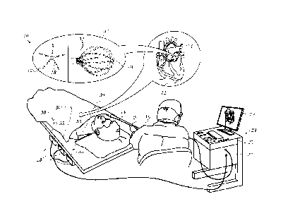
[0031] Turning now to the drawings, reference is initially made to Fig. 1,
which is a pictorial illustration of a system 10 for performing diagnostic and
therapeutic procedures on a heart 12 of a living subject, which is constructed
and operative in accordance with a disclosed embodiment of the invention. The
system comprises a catheter 14, which is percutaneously inserted by an opera-
tor 16 through the patient's vascular system into a chamber or vascular
structure
of the heart 12. The operator 16, who is typically a physician, brings the
cathe-
ter's distal tip 18 into contact with the heart wall, for example, at an
ablation tar-
get site. Electrical activation maps may be prepared, according to the methods
disclosed in U.S. Patent Nos. 6,226,542, and 6,301,496, and in commonly as-
signed U.S. Patent No. 6,892,091, whose disclosures are herein incorporated by
reference.
[0032] The system 10 may comprise a general purpose or embedded
computer processor, which is programmed with suitable software for carrying
out the functions described hereinbelow. Thus, although portions of the sys-
tem 10 shown in other drawing figures herein are shown as comprising a num-
ber of separate functional blocks, these blocks are not necessarily separate
physical entities, but rather may represent, for example, different computing
tasks or data objects stored in a memory that is accessible to the processor.
These tasks may be carried out in software running on a single processor, or
on
multiple processors. The software may be provided to the processor or proces-
sors on tangible non-transitory media, such as CD-ROM or non-volatile memory.
Alternatively or additionally, the system 10 may comprise a digital signal pro-
cessor or hard-wired logic. One commercial product embodying elements of
the system 10 is available as the CARTO 3 System, available from Biosense
Webster, Inc., 3333 Diamond Canyon Road, Diamond Bar, CA 91765. This system
may be modified by those skilled in the art to embody the principles of the in-
vention described herein.
6 of 22
CA 3015087 2018-08-23
[0033] Areas determined to be abnormal, for example by evaluation of
the electrical activation maps, can be ablated by application of thermal
energy,
e.g., by passage of radiofrequency electrical current through wires in the
cathe-
ter to one or more electrodes at the distal tip 18, which apply the
radiofrequency
energy to the myocardium. The energy is absorbed in the tissue, heating it to
a
point (typically above 50 C) at which it permanently loses its electrical
excita-
bility. When successful, this procedure creates non-conducting lesions in the
cardiac tissue, which disrupt the abnormal electrical pathway causing the ar-
rhythmia. The principles of the invention can be applied to different heart
chambers to diagnose and treat many different cardiac arrhythmias.
[0034] The catheter 14 typically comprises a handle 20, having suitable
controls on the handle to enable the operator 16 to steer, position and orient
the
distal end of the catheter as desired for the ablation. To aid the operator
16, the
distal portion of the catheter 14 contains position sensors (not shown) that
pro-
vide signals to a processor 22, located in a console 24. The processor 22 may
ful-
fill several processing functions as described below.
[0035] The catheter 14 is a multi-electrode catheter, which can be a bal-
loon or basket catheter as shown in the right portion of balloon 37, or a
spline
catheter as shown in the left portion. In any case there are multiple elec-
trodes 32, which are used as sensing electrodes and have known locations on
the basket or spline, and known relationships to one another. Thus, once the
catheter is located in the heart, for example by constructing a current
position
map, the location of each of the electrodes 32 in the heart is known. One
method
for generation of a current position map is described in commonly assigned
U.S.
Patent No. 8,478,383 to Bar-Tal et al., which is herein incorporated by
reference.
[0036] Electrical signals can be conveyed to and from the heart 12 from
the electrodes 32 located at or near the distal tip 18 of the catheter 14 via
ca-
ble 34 to the console 24. Pacing signals and other control signals may be con-
veyed from the console 24 through the cable 34 and the electrodes 32 to the
heart 12.
[0037] Wire connections 35 link the console 24 with body surface elec-
trodes 30 and other components of a positioning sub-system for measuring loca-
tion and orientation coordinates of the catheter 14. The processor 22 or
another
7 of 22
CA 3015087 2018-08-23
processor (not shown) may be an element of the positioning subsystem. The
electrodes 32 and the body surface electrodes 30 may be used to measure tissue
impedance at the ablation site as taught in U.S. Patent No. 7,536,218, issued
to
Govari et al., which is herein incorporated by reference. A temperature sen-
sor (not shown), typically a thermocouple or thermistor, may be mounted near
the distal tip 18 of the catheter 14.
[0038] The console 24 typically contains one or more ablation power
generators 25. The catheter 14 may be adapted to conduct ablative energy to
the heart using any known ablation technique, e.g., radiofrequency energy, ul-
trasound energy, and laser-produced light energy. Such methods are disclosed
in commonly assigned U.S. Patent Nos. 6,814,733, 6,997,924, and 7,156,816,
which are herein incorporated by reference.
[0039] In one embodiment, the positioning subsystem comprises a mag-
netic position tracking arrangement that determines the position and
orientation
of the catheter 14 by generating magnetic fields in a predefined working
volume
and sensing these fields at the catheter, using field generating coils 28. A
suita-
ble positioning subsystem is described in U.S. Patent No. 7,756,576, which is
hereby incorporated by reference, and in the above-noted U.S. Patent
No. 7,536,218.
[0040] As noted above, the catheter 14 is coupled to the console 24,
which enables the operator 16 to observe and regulate the functions of the
catheter 14. Console 24 includes a processor, preferably a computer with ap-
propriate signal processing circuits. The processor is coupled to drive a moni-
tor 29. The signal processing circuits typically receive, amplify, filter and
digit-
ize signals from the catheter 14, including signals generated by the above-
noted
sensors and a plurality of location sensing electrodes (not shown) located
distal-
ly in the catheter 14. The digitized signals are received and used by the con-
sole 24 and the positioning system to compute the position and orientation of
the
catheter 14 and to analyze the electrical signals from the electrodes as de-
scribed in further detail below.
[0041] Typically, the system 10 includes other elements, which are not
shown in the figures for the sake of simplicity. For example, the system 10
may
include an electrocardiogram (ECG) monitor, coupled to receive signals from
8 of 22
CA 3015087 2018-08-23
one or more body surface electrodes, so as to provide an ECG synchronization
signal to the console 24. As mentioned above, the system 10 typically also in-
cludes a reference position sensor, either on an externally applied reference
patch attached to the exterior of the subject's body, or on an internally-
placed
catheter, which is inserted into the heart 12 and maintained in a fixed
position
relative to the heart 12. The system 10 may receive image data from an
external
imaging modality, such as an MRI unit or the like and includes image
processors
that can be incorporated in or invoked by the processor 22 for generating and
displaying images.
[0042] Reference is now made to Fig. 2, which is a schematic diagram of
an ablation and active current location (ACL) circuit for use with the system
shown in Fig. 1. This arrangement is similar to that described in U.S. Patent
Ap-
plication Publications 2006/0173251, to Govari et al., and 2007/0038078, to
Osadchy, which are herein incorporated by reference. The arrangement can be
modified to operate in accordance with the principles of the present
invention. A
brief description follows for convenience of presentation.
[0043] A plurality of body surface electrodes 42, which can be adhesive
skin patches, are coupled to a body surface 44 (e.g., the skin) of subject 46.
The
body surface electrodes 42 are sometimes referred to herein as "patches". In
cardiac applications the body surface electrodes 42 are usually distributed so
as
to surround the heart, three on the chest of the subject and three on the
back.
However, the number of the body surface electrodes 42 is not critical, and
they
may be placed at convenient locations on the body surface 44 in the general vi-
cinity of the site of the medical procedure.
[0044] A control unit 48, normally disposed in the console 24 (Fig. 1), in-
cludes current measurement circuitry 50 and one or more catheter electrode
transmitters 52 for driving a current through one or more of the electrodes 42
to
one or more of the body surface electrodes 42 at respective working frequen-
cies. The control unit 48 is linked to a positioning processor (Fig. 1). The
control
unit 48 is linked to an ablator 54, which comprises at least one ablation
genera-
tor 56. Currents through the body surface electrodes 42 and an ablator body
sur-
face electrode 58 flow in a circuit with the ablation generator 56 and are
meas-
ured by respective current measurement circuits that are disposed within body
9 of 22
CA 3015087 2018-08-23
electrode receivers 60, sometimes referred to herein as "patch measurement
circuits". The body electrode receivers 60 are typically incorporated in the
con-
trol unit 48. Alternatively, they may be affixed to the body surface
electrodes 42.
Catheter electrodes are represented as measurement electrodes 62 (circles)
and a dual-purpose electrode 64 (ellipse). The dual-purpose electrode 64 func-
tions as an ablation electrode and also serves as one of the measurement elec-
trodes.
[0045] The body surface electrodes 42 are connected to the body elec-
trode receivers 60 via a patch box 66, which protects the system from ablation
and defibrillation currents. Typically the system is configured with six body
electrode receivers 60. The patch box parasitic impedances 68 (Z), are meas-
ured during production and thus known a priori. These impedances are dis-
cussed below.
[0046] Typically, although only two measurement electrodes 62 are
shown for convenience, about 80 measurement electrodes are used for imped-
ance measurements. Typically there are one or two ablation electrodes. The co-
ordinates of a catheter inside the body are determined in the positioning sys-
tem by passing currents between electrodes on the catheter and the body sur-
face electrodes 42.
[0047] The control unit 48 may also control an ablation circuit, compris-
ing ablator 54, and the dual-purpose electrode 64. The ablator 54 is typically
disposed externally to the control unit 48 and incorporates the ablation
genera-
tor 56. It connects with the ablator body surface electrode 58 and to an
ablator
filter 70, which in this example is shown within the control unit 48. However
this
location is not essential. A switch 72 configures the ablator circuit for
different
modes of operation as described below. Voltage measurement circuitry is pro-
vided for determining the output of the catheter electrode transmitters 52. It
will
be noted from inspection that the ablation circuit is connected to one of the
cath-
eter electrode transmitters 52.
[0048] Reference is now made to Fig. 3, which is a block diagram of as-
pects of the processor 22 in accordance with an embodiment of the invention.
Typically the processor 22 is located in the console 24 (Fig. 1), but it can
be re-
mote or distributed among several sites. The processor 22 may use a tracking
10 of 22
CA 3015087 2018-08-23
module, such as tracking module 74, to convert signals from the above-noted lo-
cation-sensing devices to location coordinates in a 3-dimensional frame of
refer-
ence defined by the field generating coils 28 (Fig. 1). Processor 22 is linked
to a
graphics processor 76. The graphics processor 76 is a parallel processing unit
that usually has approximately 2,000 processors.
[0049] In order determine the location of the electrodes with respect to
the wall of the heart, it is necessary to ascertain tissue contact. One useful
tech-
nique is a thermometry-based method as shown in Fig. 4, which is a sectional
view along the length of distal segment 78 of a cardiac catheter in accordance
with an embodiment of the invention. The distal segment 78 is in proximity to
tis-
sue 80, and is assumed to be immersed in fluid 82, so that tissue 80 has a
surface
29 contacting the fluid. Fluid 82 typically comprises a mixture of blood and
sa-
line solution. By way of example, distal segment 78 is assumed herein to be
formed from an insulating substrate 84 in the shape of a cylinder 86 closed by
a
generally flat surface 88 at one end. Cylinder 86 has an axis of symmetry 90.
A
curved section 92 joins flat surface 88 and cylinder 86. A typical diameter of
cyl-
inder 86 is 2.5 mm, and a typical radius of the curved section 92 is 0.5 mm.
[0050] Distal segment 78 comprises three electrodes 94, 96, 98, the elec-
trodes being insulated from each other. The electrodes 94, 96, 98 typically
com-
prise thin metal layers formed over insulating substrate 84. Typically, the
distal
tip has other electrodes, insulated from the electrodes 94, 96, 98, which for
sim-
plicity are not shown in the diagram. Tip electrode 94 has the shape of a cup
with
a flat base, and is herein also referred to as the cup electrode. Cup
electrode 94
typically has a thickness in a range from approximately 0.1 mm to
approximately
0.2 30 mm. Second and third electrodes 94, 96, are usually in the form of
rings,
and are also known as ring electrodes.
[0051] Electrodes 94, 96, 98 are connected to a controller in console 24
(Fig. 1) by wires (not shown). At least one of the electrodes is used to
ablate tis-
sue 80. Typically, during ablation, heat is generated in the ablating
electrode
and in the surrounding region. In order to dissipate the heat, small
irrigation ap-
ertures 100 in the cup electrode. The apertures 100 typically have diameters
in
an approximate range 0.1 - 0.2 ram. An irrigation tube 102 supplies saline
solu-
tion to the apertures 100, and the rate of flow of the saline solution through
the
11 of 22
CA 3015087 2018-08-23
apertures 100 (causing fluid 82 to be a mixture of blood and saline solution)
is
controlled by an irrigation module (not shown) in the console 24 (Fig. 1). The
sa-
line rate of flow is typically in the range of approximately 2 - 20 cc/minute,
but
may be higher or lower than this range.
[0052] A saline temperature sensor 104, typically a thermocouple, is lo-
cated in tube 102, and provides a signal to circuitry in the console 24 (Fig.
1)
module 56 enabling the console 24 to measure a temperature of the saline solu-
tion input to apertures 100. While the saline solution may be provided at room
ambient temperature, e.g., in a range of approximately 19 - 25 C, the solution
may be heated slightly during its flow through the catheter, so that the final
irri-
gation temperature may be slightly higher.
[0053] Typically, one or more location sensing devices 106 are incorpo-
rated in the distal tip. Devices 106 are configured to provide signals to the
pro-
cessor 22 (Fig. 1) enabling the system to ascertain the position and/or
orienta-
tion of distal segment 78,
[0054] In one embodiment distal segment 78 comprises one or more
generally similar temperature sensors 108 (by way of example, two are shown in
the diagram), which are fixedly connected, by an insulator, to the outer
surface
of cup electrode 94, so as to protrude from the surface. Sensors 108 have a
typi-
cal diameter of approximately 0.3 mm and a length of 10 approximately 1.5 mm.
In one embodiment sensors 108 are thermistors NTC Type AB6, produced by
General Electric Company of Schenectady, New York. In an alternative embod-
iment, sensors 108 comprise "F" type thermistors produced by Semitec USA
Corporation of Torrance, 15 California. By way of example, the following de-
scription assumes there are three sensors 108 symmetrically distributed with
re-
spect to axis 51, and located on a curved section 110 of the cup electrode.
Curved section 110 of the cup electrode overlays curved section 92 of the 20
dis-
tal tip. Curved section 110 is in the shape of a partial toroid, typically a
partial
torus having a tube radius of approximately 0.5 mm.
[0055] A magnified section 112 of Fig. 4 illustrates one of sensors 108 in
more detail. As shown in section 112, an insulator 114 separates sensors 108
from curved section 110 of the cup electrode 94. Insulator 114 is selected to
pro-
vide good thermal and electrical insulation, and in some embodiments insulator
12 of 22
CA 3015087 2018-08-23
114 may comprise an adhesive that bonds sensors 108 to curved section 110.
Wires 116 connect sensors 108 to the console 24 (Fig. 1).
[0056] By having sensors 108 protrude from the outer surface of cup elec-
trode 94, the sensors 108 are able to intimately contact tissue 80. The proces-
sor 22 (Fig. 1) is thus able to use signals from the sensors 108 to provide
direct
temperature measurements of the tissue 80 In one embodiment the sensors 108
protrude from the outer surface of the electrode 94 by no more than 0.7 mm,
and
typically by approximately 0.5 mm.
[0057] Additional details of thermometry based determination of tissue
contact are found in commonly assigned U.S. Patent Application Publication No.
20170079738, which is herein incorporated by reference. Alternatively, tissue
contact can be determined using a contact force sensor as described, for exam-
ple, in commonly assigned U.S. Patent Application Publication No. 20170127974,
which is herein incorporated by reference. Further alternatively tissue
contact
can be determined using impedance-based methods as described U.S. Patent
Application Publication Nos. 2008/0288038 and 2008/0275465, both by Sauarav
et al., which are herein incorporated by reference, or using ultrasonic
transduc-
ers, as described in copending, commonly assigned Application No. 15637191,
which is herein incorporated by reference. The methods may be combined with
other filters, for example respiratory gating to exclude artefacts.
[0058] Reference is now made to Fig. 5, which is a schematic illustration
of points 118 of a mesh in accordance with an embodiment of the invention.
Points are registered by electrodes 32 (Fig. 1), when in contact with the endo-
cardial surface of the heart 12. Typically during the mapping referred to
above,
processor 22 initially stores 3-dimensional coordinates of points 118 as meas-
ured in a 3-dimensional frame of reference 120 defined by the field generating
coils 28. The processor 22 then connects 3-dimensional coordinates of points
118, herein also termed 3-dimensional vertices, by line segments 122 to pro-
duce a set of connected 3-dimensional triangles, e.g., triangles 124, 126,
128.
.. The procedures described in commonly assigned U.S. Patent Application Publi-
cation No. 20150164356, entitled Dynamic Feature Rich Anatomical
Reconstruction
from a Point Cloud, which is herein incorporated by reference, may be used to
produce a mesh 130. Other suitable algorithms include the ball-pivoting algo-
13 of 22
CA 3015087 2018-08-23
rithm to produce the mesh 130. Typically, if the ball-pivoting algorithm is
used, a
size of the ball is set to correspond to the size of the voxels referred to
below.
Alternatively, the mesh may be generated as a Delaunay triangulation. Elements
of the mesh each have 3-dimensional coordinates.
[0059] In one application the triangular mesh 130 models the endocardial
surface. The processor 22 (Fig. 3) uses the graphics processor 76 to render
the
mesh 130 into an image for display on the monitor 29 (Fig. 1).
[0060] Initially, realtime positions on the mesh 130 are placed in registra-
tion with an image of the heart that was obtained by other modalities, such as
computed tomography or magnetic resonance imaging (referred to herein as a
"CT/MRI image"). Once this is done points of interest may be transformed from
coordinates of the image to coordinates of the mesh 130.
[0061] Nevertheless, residual differences between the CT/MRI image
and the mesh remain after the registration procedure. These differences are re-
duced according to embodiments of the invention. Reference is now made to
Fig. 6, which is a flow chart of a method of fitting a 3-dimensional model of
a
heart to a CT/MRI image in accordance with an embodiment of the invention.
The process steps are shown in a particular linear sequence for clarity of
presen-
tation. However, it will be evident that many of them can be performed in
paral-
lel, asynchronously, or in different orders. Those skilled in the art will
also ap-
preciate that a process could alternatively be represented as a number of
inter-
related states or events, e.g., in a state diagram. Moreover, not all
illustrated
process steps may be required to implement the method. The algorithm com-
prises:
[0062] For each mapped point, preferably filtered by cardiorespiratory
gating:
[0063] 1. Identify all the vertices in the original mesh that are within a
specified radius from the filtered point.
[0064] 2. For each identified vertex calculate a weight factor based on its
distance to the filtered point. In one embodiment the weight factor is the
inverse
square of the distance
[0065] 3. Shift each identified vertex towards the filtered point by the
weight calculated in step 2.
14 of 22
CA 3015087 2018-08-23
[0066] At initial step 132 the heart is catheterized conventionally, typical-
ly with a multi-electrode mapping catheter, such as a balloon or basket
catheter
in which the electrodes have known locations on the basket or spline, and have
known relationships to one another.
[0067] Next, at step 134 it is ascertained that the electrodes are in contact
with the wall of the heart, using one of the above-described methods. After
com-
pletion of step 134 current readings are taken at step 136 to determine the
loca-
tions of the electrodes in current position map in order to construct a
current po-
sition map that identifies the location of each of the electrodes 32 in the
heart.
One method for generation of a current position map employs the circuitry
shown in Fig. 2. Details are described in the above-noted U.S. Patent No.
8,478,383.
[0068] Next, at step 138 the current position map is placed in registration
with a CT/MRI image. The teachings of U.S. Patent Nos. 7517318 and 8320711
and in U.S. Patent Application Publication No. 20160120426, all of which are
commonly assigned and herein incorporated by reference, may be used to ac-
complish this step. Alternatively, the CARTOMERGETM module and other facili-
ties of the above-noted CARTO system can accomplish this step using images of
the heart prepared at the same or a different session.
[0069] Next, at step 140 a 3-dimensional model, for example the triangu-
lar mesh 130 (Fig. 5), is prepared based on the ACL readings and the current
position map. This can be accomplished using the teachings of the above-
noted U.S. Patent Application Publication No. 20150164356. Vertices of the ma-
trix are assigned mapping coordinates corresponding to the electrodes of the
catheter 14.
[0070] Next a mesh-fitting algorithm is performed. For each vertex in the
mesh all mapped points within a geodesic distance GD are identified and re-
spective weights for the mapped points (1/GDA2) assigned with respect to that
vertex. A mapped point may lie within an influence radius of a more than one
vertex, in which case respective weights for the vertices are assigned for
that
mapped point. The vertices are shifted toward mapped points within respective
15 of 22
CA 3015087 2018-08-23
influence radii in accordance with the assigned weights. The actual shift of a
ver-
tex can be represented as a 3-dimensional vector sum.
[0071] The algorithm is repeated so long as significant changes in the
vertices continue to occur, or some other termination criterion is reached.
[0072] At step 142 a mapped point is selected. All original vertices within
a predefined distance, typically 2-15 mm, of the current mapped point will be
evaluated in the following steps. "Original vertices" refers to the positions
of the
vertices at the beginning of the current iteration of the algorithm.
[0073] At step 143 an original vertex of the mesh 130 is chosen. Then, at
step 144 a geodesic distance to the closest corresponding map location (in an
appropriately transposed 3-dimensional coordinate system) is determined.
[0074] Next, at decision step 146, it is determined if the distance deter-
mined in step 144 is less than the predetermined distance. If the
determination
at step 144 is affirmative, then control proceeds to step 148. Weights are as-
signed according to the inverse square of the distance between the vertex and
the map location.
[0075] After performing step 148 or if the determination at decision
step 146 is negative, then at decision step 150, it is determined if more
vertices
need to be adjusted. If the determination at decision step 150 is affirmative,
then
.. control returns to step 143 to iterate the loop.
[0076] If the determination at decision step 150 is negative then, at deci-
sion step 151 it is determined if more mapped points remain to be evaluated.
If
the determination at decision step 151 is affirmative, then control returns to
step 142.
[0077] If the determination at decision step 151 is negative, then at deci-
sion step 153 it is determined if vertex shifts are required, i.e., whether
the algo-
rithm has converged so that all required shifts are less than some minimal
value,
or some other termination condition has occurred, e.g., a given number of
itera-
tions have been performed.
[0078] If the determination at decision step 153 is negative then, the pro-
cedure ends at final step 152. Otherwise, the calculated shifts are carried
out at
step 155. The mesh 130 is adjusted by shifting the vertices toward the corre-
16 of 22
CA 3015087 2018-08-23
sponding map locations in accordance with the assigned weights. Control then
returns to step 142 to iterate the algorithm using the new mesh positions.
[0079] Reference is now made to Fig. 7, which is a schematic diagram of
a portion of a triangular mesh can be processed in accordance with an embodi-
ment of the invention. The mesh as originally constructed in step 140 (Fig. 6)
has
vertices 154, 156, 158. Mapped points according to the ACL, which has been
placed in registration with a CT/MRI image are indicated as points 160, 162,
164,
166. The radii of identical circles 168, 170, 172 centered on the vertices
154, 156,
158 represent the maximum distance between the vertices and the mapped
points that produce a shift in the vertices.
[0080] Points 162, 164 and vertex 154 lie within circle 172. However,
point 162 is closer than point 164 to vertex 154. Accordingly vertex 154 is
shifted
toward point 162 a distance DI, and vertex 154 assumes a first new position.
Point 164 is also within the circle 172. Therefore a new weighting is
calculated
based on the original distance between the point 164 and vertex 154. A second
shift in the direction of point 164 is performed. The final position 174 is
equiva-
lent to the sum of weighted vectors directed from vertex 154 toward point 162
and from vertex 154 toward point 164 as indicated by vector diagram 165.
[0081] The distance between vertex 156 and the closest mapped
point 160 exceeds the radius of circle 168. Vertex 156 is therefore not
shifted.
[0082] Vertex 158 and point 166 lie within circle 170. It will be noted that
point 166 is nearly at the boundary of circle 170, while the point 162 is
relatively
closer to the vertex 154, being approximately half-way between the vertex 154
and the boundary of circle 172. Vertex 158 is shifted toward point 166 by a
dis-
tance D2 to a position 176. The distances Dl and D2 are aligned at the left of
the
figure. It is evident that distance D2 is less that than distance Dl.
[0083] The adjusted matrix is indicated by broken lines joining the posi-
tions 174, 176 and the vertex 156.
[0084] It will be apparent that when a vertex is shifted, its neighbors are
also affected. This effect can be seen in Fig. 8 and Fig. 9, which show a
portion of
a matrix 178 that simulates a portion of a 3-dimensional surface of a heart in
reg-
istration with a mapped point 180. Vertex 182 is the closest vertex to the
mapped
point 180.
17 of 22
CA 3015087 2018-08-23
[0085] Fig. 8 illustrates the relationship between the mapped point 180
and vertex 182 prior to the first vertex shift in step 155 (Fig. 6). Fig. 9
shows ma-
trix 178 after performance of step 155 (the effects are intentionally
exaggerated
for clarity). Vertex 182 has now been displaced toward mapped point 180.
Neighboring vertices 184, 186, 188 are also influenced by proximity to mapped
point 180 and hence are displaced toward mapped point 180. The displacements
of vertices 184, 186, 188 are less than that of vertex 182, as they are more
distant
from the mapped point 180, and their assigned weights in step 148 (Fig. 6) are
correspondingly lower than that of vertex 182.
[0086] An effect of the displacements is to draw vertices 184, 186, 188
away from vertices that are even more distant from mapped point 180, as evi-
denced by the difference in relationship between vertex 184 and distant ver-
tex 196 in Fig. 8 and Fig. 9, and also by distortion of areas 190, 192, 194 in
Fig. 9.
Vertex 196 is unaffected by mapped point 180 and would be ignored in decision
step 146 (Fig. 6).
[0087] It will be appreciated by persons skilled in the art that the present
invention is not limited to what has been particularly shown and described
hereinabove. Rather, the scope of the present invention includes both
combinations and sub-combinations of the various features described
.. hereinabove, as well as variations and modifications thereof that are not
in the
prior art, which would occur to persons skilled in the art upon reading the
foregoing description.
18 of 22
CA 3015087 2018-08-23