Note: Descriptions are shown in the official language in which they were submitted.
CA 03015230 2018-08-21
WO 2017/147711
PCT/CA2017/050283
1NTAKE FILTER FOR WATER COLLECTION SYSTEM WITH PRESSURE ACTIVATED
BACKWASH VALVE
RELATED APPLICATIONS
[0001] This application claims priority from US provisional patent
application
62/302,988 filed on March 3, 2016 and US provisional patent application
62/305,625 filed on
March 9, 2016, both of which are incorporated herein by reference.
FIELD
[0002] This specification relates to water filtration.
BACKGROUND
[0003] US Patent 8,377,291 describes a water recycling system that
can be used for
reclaiming and recycling grey water to provide water for landscaping or
sanitary facilities
such as a toilet. The water recycling system includes a tank, an influx pipe
with a filter
screen, and a pump. The filter screen covers an opening in the bottom of the
influx pipe.
The part of the influx pipe containing the filter screen is sloped. At least
some influent water
passing through the influx pipe falls through the filter screen to be
collected in the tank. Any
excess influent water continues past the filter screen and flows through the
influx pipe to an
external sanitary drain. When filtered water is drawn from the tank, a portion
of it is sprayed
against the bottom of the screen to force material off the filter screen and
into the influx pipe.
INTRODUCTION
[0004] This specification describes an intake filter. The intake
filter may be used, for
example, in a grey water collection and recycling system, in particular a
system that collects
grey water from baths or showers or both for re-use in toilet flushing. The
following
paragraphs describe various features of the intake filter. However, a claimed
invention may
involve only a subset of the features in this summary, or a subset of features
in this summary
combined with one or more features in the detailed description to follow.
[0005] In brief, the intake filter provides essentially dead-end filtration
during normal
operation. An influent by-pass may be provided, but the by-pass is located at
a material
elevation (for example 10 cm or more above the top of the screen) or so as to
provide a
material upstream hold-up volume (for example 10 liters or more above the top
of the
- 1 -
CA 03015230 2018-08-21
WO 2017/147711
PCT/CA2017/050283
screen). With such an elevated by-pass or hold-up volume, it is more likely
that at least most
of the water released from a shower (about 65 liters on average) will pass
through the intake
filter even if its filter element is partially fouled when compared to a
system with open
channel flow past the filter element. The ability to process the water
released from a shower
through a partially fouled filter element in turn allows the filter element to
be cleaned less
frequently. Cleaning a filter element consumes product or fresh water, and so
every filter
cleaning reduces the net amount of water collected through the intake filter.
Preferably,
cleaning is performed on an on-condition basis (based on an assessment of the
condition of
the filter element), for example when permeability of the filter element
declines to a point at
.. which the influent by-pass is being used, or is likely to be used soon. The
condition of the
filter can be determined indirectly by monitoring one or more hydraulic
conditions (i.e. the
presence or pressure of water) upstream of the filter element or in the
influent by-pass.
When the filter element is cleaned, for example by backwashing, a lower feed
side outlet
(lower than the influent by-pass) is opened to more efficiently remove solids
from the intake
filter. In an embodiment, a stream of pressurized water is used to backwash
the filter and
also moves one or more valves to direct backwash water to a sanitary drain.
The water may
move the one or more valves, and/or solids retained by the screen, by way or
impulse,
entraining a valve or solids in flow, flotation, or a combination of forces.
[0006] In a process described herein, influent water is filtered
through a filter element.
One or more sensors upstream of the filter element are monitored to determine
if filter
permeability has declined. For example, a sensor may check for the presence of
water at a
selected location upstream of the filter. If filter permeability has declined,
the filter is cleaned,
for example by releasing pressurized water on the downstream side of the
filter. Optionally,
pressurized water also impinges against, and moves, at least one valve. In one
example, an
effluent outlet valve is closed, which can cause the water to flow in a
reverse direction
through the screen, and a waste drain valve is opened.
[0007] In an apparatus described herein, a filter element is located
between
upstream and downstream conduit systems. The downstream conduit system has an
effluent drain with a cooperating effluent drain valve. The upstream conduit
system has a
waste drain with a cooperating waste drain valve. The effluent drain valve is
mechanically
linked to the waste drain valve. A nozzle supplied with pressurized water is
directed at the
effluent drain valve. Optionally, the upstream conduit system has a sensor,
for example a
water proximity sensor.
- 2 -
CA 03015230 2018-08-21
WO 2017/147711
PCT/CA2017/050283
[0008] Optionally, the pressurized water used to clean the filter may
be assisted by
air. The air can be mixed with the water to create a two-phase flow or there
may be separate
streams of air and water. The water can be mixed with air upstream of a
nozzle, within a
nozzle, or downstream of a nozzle that sprays the pressurized water into the
filter.
BRIEF DESCRIPTION OF THE FIGURES
[0009] Figure 1 is a schematic overview of a grey water recycling
system in a house.
[0010] Figure 2A is a front view of an intake filter.
[0011] Figure 2B is a front view of the intake filter of Figure 2A
with a front panel
removed.
[0012] Figure 20 is a back view of the intake filter of Figure 2A.
[0013] Figure 3A is sectioned view of the intake filter of Figure 2A
showing an effluent
valve in an open position.
[0014] Figure 3B is a sectioned view of the intake filter of Figure
2A showing an
effluent valve in a closed position.
[0015] Figure 30 is a front view of the intake filter of Figure 2A
with a front panel
removed (a duplicate of Figure 2B) reproduced for convenience and showing the
effluent
valve in an open position and a waste drain valve closed.
[0016] Figure 3D is a front view of the intake filter of Figure 2A
with a front panel
removed showing the effluent valve in a closed position and the waste drain
valve in an open
position.
[0017] Figure 4 is a schematic drawing of a control system for the
intake filter of
Figure 2A or Figure 5A.
[0018] Figure 5A is a front view of another intake filter.
[0019] Figure 5B is a back view of the intake filter of Figure 5A.
[0020] Figure 5C is a front view of the intake filter of Figure 5A
with a front panel
removed, an effluent valve closed and a waste drain valve open.
[0021] Figure 5D is a sectioned view of the intake filter of Figure
5C.
[0022] Figure 5E is a front view of the intake filter of Figure 5A
with a front panel
removed, an effluent valve open and a waste drain valve closed.
[0023] Figure 5F is a sectioned view of the intake filter of Figure
5E.
- 3 -
CA 03015230 2018-08-21
WO 2017/147711
PCT/CA2017/050283
DETAILED DESCRIPTION
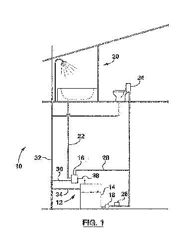
[0024] Figure 1 shows a house 10 with a grey water recycling system
12. Grey water
recycling system 12 has a collection tank 14, an intake filter 16 and a pump
18. Grey water
collected from a bathtub or shower 20 flows down grey water drain 22 to the
intake filter 16.
Intake filter 16 filters the grey water and releases it through an effluent
drain 38 to collection
tank 14. For example, the intake filter 16 may separate solids, for example,
hair, pieces of
soap and other debris, from the grey water. Optionally, further treatment may
occur in the
collection tank 14, between the intake filter 16 and the collection tank 14 or
after the
collection tank 14. Pump 18 draws filtered water from the collection tank 14
and delivers it
under pressure to a toilet 24. Pressure control unit 26 starts pump 18 when it
senses a
pressure at or below a pre-selected minimum and stops pump 18 when it senses a
pressure
at or above a pre-selected maximum. A pressurized supply line 28 directs
pressurized water
for backwashing to the intake filter 16 from the outlet of pump 18 or from
another source, for
example a municipal water supply or a well. A waste drain line 30 connects the
intake filter
.. to a sanitary drain stack 32. Sanitary drain stack 32 is connected to a
sewer, septic system
or other wastewater treatment system in or outside of the house 10. The
collection tank 14
may also have a connection to a plumbing vent and an overflow line 34
connected to the
sanitary drain stack 32.
[0025] Grey water flows automatically by gravity through the intake
filter 16 to the
collection tank 14 as the grey water is produced or soon after. Cleaning of
the intake filter 16
occurs on an on-condition basis, for example based on the permeability of a
filter element
within the intake filter 16, which may be indicated by the use or anticipated
use of a by-pass
within the intake filter 16. Cleaning the intake filter 16 can be by way of a
backwash using
pressurized water, optionally assisted by air. Backwash waste water and water
in the by-
pass flow to the sanitary drain stack 32.
[0026] Figure 4 shows a control system 36 for the intake filter 16.
The control system
includes a sensor 39, controller 40 and supply valve 42. The sensor 39
monitors a condition
related to the condition, for example permeability, of the intake filter 16
and sends signals to
the controller 40. The controller 40 receives the signals and determines
whether a backwash
is required. When a backwash is required, the controller 40 opens supply valve
42, for
example by energizing a solenoid. Water under pressure is then provided under
pressure to
the intake filter 16 for backwashing. Optionally, when a backwash is required,
the controller
turns on air pump 100 (if air pump 100 is not already on, for example to
assist in a further
- 4 -
CA 03015230 2018-08-21
WO 2017/147711
PCT/CA2017/050283
treatment process) and opens air valve 102. Compressed air flows through air
supply line
104 to the intake filter 16. The compressed air may mix with water provided to
the intake
filter before reaching the intake filter 16, in a nozzle injecting the water
and air into the intake
filter 16, or after entering the intake filter 16. Further details of the flow
of grey water and
backwash water through examples of the intake filter 16 will be provided
below.
[0027] Figures 2A to 3D show further details of a first example of an
intake filter 16.
Referring to Figures 2A, 2B and 2C, forward path 52 indicates the path of grey
water through
the intake filter during ordinary operation. Grey water from showers or baths
enters the
intake filter 16 through a grey water inlet 50. The grey water passes through
a filter element
56, for example a cylindrical screen. After passing through the filter element
56, the filtered
grey water passes by an effluent outlet valve 60 and leaves the intake filter
16 through a
collection tank inlet connection 62. The filter element 56 can be removed for
replacement or
repair through access cover 94.
[0028] In the example shown, effluent outlet valve 60 is one flapper
of a dual flapper
assembly 80. The other flapper is waste valve 78. The two flappers 60, 78
share and
extend from a common pin 70 rotating in bushings 72. Outlet valve 60, when
moved to the
position shown in Figure 3D, covers and substantially seals the collection
tank inlet
connection 62. Under normal operation, the dual-flapper assembly 80 is in the
position
shown in Figures 3C and 2B. In this position, the dual-flapper assembly 80
allows incoming
grey water to flow into the grey water inlet 50, through the filter element
56, and into the
collection tank 14.
[0029] Depending on the condition of the filter element 56, incoming
grey water may
rise temporarily in part of a by-pass 54. Optionally, a portion of the by-pass
54 above the
filter element 56 is made of a larger diameter pipe to provide a by-pass tank
58. When the
filter element 56 begins to clog, part of the by-pass 54, and in particular
the bypass tank 58,
will temporarily retain a certain volume of water below the point of highest
elevation of the by-
pass 54. The part of the by-pass 54 upstream of its highest elevation acts as
a buffer to
allow more time, and increased static pressure, for the incoming grey water to
pass through
the filter element 56 instead of leaving the intake filter 16 through the by-
pass 54. If the filter
element 56 clogs completely, or nearly so, water may rise up above the bypass
tank 58 to
the level of sensor 38, which in this example is a water proximity sensor.
Sensor 38 may be
any sort of sensor that can send a signal when water is at, or near, the
sensor. For example,
sensor 38 could be a capacitive proximity sensor or an optical sensor.
- 5 -
CA 03015230 2018-08-21
WO 2017/147711
PCT/CA2017/050283
[0030] Any grey water rising above the sensor 38 can by-pass the
filter element 56
and leave through the rest of the by-pass 54 to a sanitary drain connection
64, as shown by
the dashed overflow path 66 in Figure 2B. Optionally, overflow line 34 from
collection tank
14 can be connected to the by-pass 54 through collection tank overflow
connection 92
.. (shown in Figure 20). Any collection tank overflow water then passes
through sanitary drain
connection 64 rather than being connected directly to sanitary drain stack 32
as shown in
Figure 1. An optional collection tank purge connection 96 to the by-pass 54
can be
connected to pump 18 through a valve and pressurized supply line 28.
Optionally, collection
tank purge connection 96 can be connected to a separate, dedicate collection
tank purge
pump, particularly if there are intervening treatment units between collection
tank 14 and
pump 18. With either pump, the collection tank 14 can be drained through the
sanitary drain
connection 64 if required.
[0031] Water sensed at the elevation of sensor 38 indicates that grey
water has by-
passed the filter element 56 or is likely to by-pass the filter element 56
soon if the filter
.. element 56 continues to foul. The filter element 56 is therefore cleaned
after the sensor 39
detects water, for example by backwashing the filter element 56.
Alternatively, a sensor
could be placed in another location, for example in the by-pass 54 downstream
of its point of
highest elevation or in the grey water drain 22. In other alternatives, a
sensor could measure
water pressure, for example static head of water anywhere upstream of the
filter element 56
.. or the activation of a one way valve (i.e. a sanitary check valve) in or
downstream of the by-
pass 54. In another alternative, a sensor could detect the presence of water
at a location
upstream of the filter element 56 and the controller 40 could measure the time
that water is
present in this location. This would provide a means of determining the time
taken for water
from a shower to pass through the filter element 56, which is an indicator of
permeability or
.. fouling condition.
[0032] Preferably, the controller 40 waits after receiving a signal
from sensor 38
before cleaning the filter element 56. Optionally, a short wait period (for
example 5 or 10
minutes) may allow grey water in the by-pass tank 58 to be filtered or allow
water above
waste valve 78 to drain. Alternatively, a longer wait period can be provided
to delay cleaning
.. until a time of day when a shower during the backwash is unlikely. After
the wait period,
controller 40 opens supply valve 42. Preferably, supply valve 42 is a solenoid
connected to
the outlet of pump 18, which allows the filter element 56 to be cleaned using
filtered grey
water. The pressurized supply line 28 is connected to a backwash water
connection 76.
- 6 -
CA 03015230 2018-08-21
WO 2017/147711
PCT/CA2017/050283
When a backwash is activated, pressurized water pushes the outlet valve 60
into a position
that prevents flow into the collection tank 14 and instead directs the
pressurized water
backwards through the filter element 56. Closing the outlet valve 60
preferably also opens a
waste valve 78, the waste valve 78 being the other flapper of the dual flapper
assembly 80.
Waste valve 78, when closed, covers a port leading to the sanitary drain
connection 64.
Opening waste valve 78 connects the upstream side of the filter element 56 to
the sanitary
drain connection 64. This allows backwashed debris from filter element 56 to
drain under
gravity into the waste drain line 30 without having to flow over the point of
highest elevation
in by-pass 54. The controller 40 closes supply valve 42 to end the backwash,
for example
.. after a predetermined time from opening supply valve 42. In the absence of
flowing water
from the supply valve 42, the dual flapper assembly 80 returns to its normal
position, for
example by gravity or a spring, and the regular flow of grey water through the
filter element
56 to the collection tank inlet 14 resumes with the next shower.
[0033] The position of the dual flapper assembly 80 during a backwash
is shown in
Figure 3D. In this position, pressurized water enters backwash water inlet 76
and then flows
through the screen element 56 to the sanitary drain stack 32. The path of
flowing water
through the intake filter 16 is shown as backwash flow path 90 in Figure 3D.
As shown in
Figures 3A and 3B, the backwash water inlet 76 may be connected to a nozzle 92
aimed at
the outlet valve 60. The nozzle 90 helps direct the impulse of incoming
pressurized water
against the outlet valve 60. Optionally, a partition 94 separating the outlet
valve 60 from
waste valve 78 can have a small hole at or near its bottom edge, or the
partition 94 could be
porous and act as the filter element 56. This allows water above waste valve
78 to drain into
the collection tank between showers, which makes it easier for incoming
pressurized water to
lift the waste valve 78.
[0034] Figures 5A to 5F show details of a second example of an intake
filter 16. This
second example will be referred to as second intake filter 16' in the
description below and
Figures 5A to 5F. Elements that are substantially unchanged from the features
shown in
Figures 2A to 3D will be given the same reference numbers in Figures 5A to 5F.
Unless it is
inconsistent with anything below, the description of an element of the first
intake filter 16 of
Figures 2A to 3D will apply to an element having the same reference number in
Figures 5A
to 5F.
[0035] The second intake filter 16' has a second filter element 56'.
Second filter
element 56' is a flat screen oriented horizontally. Optionally, second filter
element 56' may
- 7 -
CA 03015230 2018-08-21
WO 2017/147711
PCT/CA2017/050283
slope downwards towards the waste valve 78. An optional dam 57, preferably
extending
above the highest point of second filter element 56', temporarily retains a
small volume of
water over the second filter element 56' during backwashing. This small volume
of water can
help wet solids that were retained by the screen. The small volume of water
can also reduce
the tendency for water to flow preferentially through relatively un-fouled or
more easily
cleaned parts of the second filter element. The dam 57 may optionally have a
notch or spout
(not shown) to help backwashed solids flow over the dam 57. Mixing the
backwash water
with air also helps backwashed solids flow over the dam 57. Solids retained by
the second
filter element 56' are removed primarily by being lifted upwards by water and
air rising
through the second filter element 56' after the volume within the second
intake filter 16'
downstream of the second filter element 56' is filled. Optionally, one or both
of the water or
air streams, or parts of one or both of the water or air stream, could be
directed at the second
filter element 56' to help dislodge retained solids.
[0036] The by-pass 54 of second intake filter 16' does not include a
bypass tank 58.
The part of the by-pass 54 upstream of its highest elevation has a plurality
of sensors 38, for
example 2, at different elevations. A lower sensor 38 may be used to activate
a backwash.
An upper sensor 38 may be used to send an alert that the second intake filter
16' should be
inspected. A bathtub might be used for exceptional purposes, for example
washing off paint
or other chemicals or bathing a muddy, shedding dog, that in some combinations
could
require the second filter element 56' to need to be removed for manual
cleaning.
[0037] During a backwash, the controller 40 opens supply valve 42,
turns on air
pump 100 and opens air valve 102, for example for a predetermined time. The
air supply
line 104 is connected to an air inlet 77. In the example shown, air inlet 77
and backwash
water inlet 76 are connected to a nozzle 93 passing through a floor of the
second intake filter
16' downstream of the second filter element 56'. The nozzle 93 does not mix
the air and
water but instead releases generally parallel streams of air and water both
directed at the
outlet valve 60. Optionally, the outlet valve 60 has a hood 61 to intercept
the air and water
even when the outlet valve 60 is closed. The water and air mix inside the
second intake filter
16', generally before rising through the second filter element 56'.
Alternatively, the air and
water could be mixed together before they are injected into the second intake
filter 16'.
[0038] The figures are intended to shown just some optional examples
of an intake
filer 16. An intake filter could also be made with various modifications. For
example,
additional or alternative pressurized water nozzles could clean a filter
element by directing
- 8 -
CA 03015230 2018-08-21
WO 2017/147711
PCT/CA2017/050283
water across the upstream side of a filter element rather than backwashing the
filter element.
The filter element could be located within a pipe section rather than a
rectangular box as
shown. A flappers could extend downwards from an axle, open outwards rather
than
inwards, be orthogonal to another flapper, or be linked by a pushrod or other
mechanical
means to another flapper instead of having a common axle. One or more flappers
could be
actuated by mechanical, electrical, pneumatic or other actuators instead of
moving in
response to flowing water. In one option, an influx body with a filter element
at the bottom
(for example as described in US 8,377,291) could have a flapper valve
downstream of the
filter element. A rotational sensor on the flapper valve can provide a signal
(caused for
.. example by a certain degree of rotation during a shower) indicating that an
undesirable
amount of water is flowing over rather than through the filter element, and
that the filter
element needs to be cleaned. An intake filter as described herein may be part
of a grey
water treatment system as described in US provisional patent application
62/305,625 filed on
March 9, 2016.
- 9 -