Note: Descriptions are shown in the official language in which they were submitted.
CA 03015511 2018-08-22
WO 2017/147199 PCT/US2017/018968
Title: Fibers for Reinforcing Concrete
This application claims priority to and the benefit of, and incorporates the
entirety of, US Provisional Application No. 62/298,287 filed on February 22,
2016.
The field of the invention is discrete macrosynthetic fibers for use in
reinforcing concrete.
The macrosynthetic fiber, the invention disclosed herein, comprises a blend of
polypropylene and polyethylene resins, or can comprise one or the other of
these
materials. As used herein, "macrosynthetic fiber" is a fiber having a linear
density
equal to or greater than 580 deniers and a diameter equal to or greater than
three
millimeters (3 mm). In a preferred embodiment of the fiber, it is i80o deniers
with
an approximate range of +/- 30%. ASTM standard D7508 is hereby incorporated by
reference. The fiber is flexible compared to other fibers, as can be
demonstrated in
testing of the individual fiber's modulus of elasticity. The flexibility of
the fiber, along
with its other properties and configuration, aid in the workability of the
fiber into the
concrete in a uniform manner, adding to the strength of the hardened concrete.
Brief Description of the Figures
CA 03015511 2018-08-22
WO 2017/147199 PCT/US2017/018968
Figs. 1A-1C are cross-sections of some examples of fibers comprising a U-
shape embodiment, and Fig. 1D is a schematic of the axes of the U-shape
embodiments.
Figs. 2A-2B are cross-sections of some examples of fibers comprising an H-
shape embodiment, and Fig. 2C is a schematic of the axes of the H-shape
embodiment.
Fig. 3 is a cross section of the fiber embodiment of Fig. iB, showing
additional
detail.
Fig. 4 is a cross-section of the fiber embodiment of Fig. 2B, showing
additional
detail.
Fig. 5 is a perspective view of a shortened section of the fiber in an
additional
U-shape embodiment.
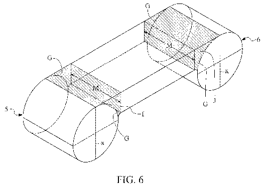
Fig. 6 is the same as Fig. 5, with the areas of joinder shaded.
Fig. 7 is a perspective view of a short section of a U-shape embodiment with
indentations from scoring.
Fig. 7A is a perspective view of a U-shape embodiment of an entire fiber as
shown in cross-section in Fig. iB. Here, no indentations are depicted as
depicted in
Fig. 7.
Fig. 8 is s side view of the scoring tool and a fiber (before cutting) in the
process of being scored with indentations.
Fig. 9 shows test results of the present invention fiber at a dose of 3.0
pounds
per cubic yard of concrete, as further described in Table 3.
Fig. lo shows test results of the present invention fiber at a dose of 5.0
pounds
per cubic yard of concrete, as further described in Table 4.
Fig. 11 shows test results of the present invention fiber at a dose of 7.0
pounds
per cubic yard of concrete, as further described in Table 5.
Fig. 12 shows test results of the present invention fiber at a dose of 10.0
pounds per cubic yard of concrete, as further described in Table 6.
Fig. 13 shows comparative test results of the present invention and prior art
fibers A-I with loading values at L/600 and L/150 at a dose of 5.0 pcy, with
data from
Table 8.
Fig. 14 shows test results of prior art fiber A at a dose of 5.0 pounds per
cubic
yard of concrete, as further described in Table 9.
2
CA 03015511 2018-08-22
WO 2017/147199 PCT/US2017/018968
Fig. 15 shows test results of prior art fiber B at a dose of 5.0 pounds per
cubic
yard of concrete, as further described in Table 10.
Fig. 16 shows test results of prior art fiber C at a dose of 5.0 pounds per
cubic
yard of concrete, as further described in Table
Fig. 17 shows test results of prior art fiber D at a dose of 5.0 pounds per
cubic
yard of concrete, as further described in Table 12.
Fig. 18 shows test results of prior art fiber E at a dose of 5.0 pounds per
cubic
yard of concrete, as further described in Table 13.
Fig. 19 shows test results of prior art fiber F at a dose of 5.0 pounds per
cubic
yard of concrete, as further described in Table 14.
Fig. 20 shows test results of prior art fiber G at a dose of 5.0 pounds per
cubic
yard of concrete, as further described in Table 15.
Fig. 21 shows test results of prior art fiber H at a dose of 5.0 pounds per
cubic
yard of concrete, as further described in Table 16.
Fig. 22 shows test results of prior art fiber I at a dose of 5.0 pounds per
cubic
yard of concrete, as further described in Table 17.
Fig. 23 is a depiction of summary test results on the present invention fibers
at
doses of fiber at 3.0, 5.0, 7.0 and 10.0 pounds per cubic yard of concrete
with data
taken from Table 2.
Fig. 24 depicts an embodiment of the present invention without areas of
joinder.
Fig. 25 is a photograph of individual fibers of the present invention, as well
as
in pucks, or packages, for mixing in concrete.
The present invention embodies a number of unique configurations to
maximize surface area to enhance mechanical bonding of the fiber to hardened
concrete. The cross-section of one embodiment of the invention comprises a "U-
shape" as shown, for example, in Figs. 1A-1C to allow the un-hardened concrete
mix
to enter a single valley 22 (i.e., open space) defined by the walls 5, 6 and
the central
panel 2 of the fiber embodiment. The cross-section of another embodiment
comprises an "H-shape" as shown, for example, in Figs. 2A-B which also allows
the
un-hardened concrete mix to enter the two valleys 22 of this embodiment of the
fiber
and bond to the walls 5, 6, central panel 2 and the area of joinder I, J,
particularly
the radius 17 or two or more angles. These embodiments provide extra surface
area
for bonding and also allow the concrete hardened inside the valley(s) 22 and
exterior
3
CA 03015511 2018-08-22
WO 2017/147199 PCT/US2017/018968
to the valley(s) to provide pressure to the walls 5, 6 of the fiber to reduce
the effect of
Poisson's Ratio. Poisson's Ratio is the ratio of the transverse contraction
strain to the
longitudinal extension strain in the direction of stretching force, i.e., the
fiber
becomes thinner as it is elongated. For example, gripping a rubber band
between the
thumb and forefinger of both hands and stretching is a simple demonstration of
Poisson's Ratio. With the present invention fibers, hardened concrete which is
bonded to both sides of the walls 5, 6 in the U-shape embodiment or the H-
shape
embodiment resists the elongation of the fiber and thus adds to the strength
of the
reinforced concrete. The hardened concrete bonded in the valley(s) 22 of the U-
shape or of the H-shape coupled with the hardened concrete bonded to the
exterior
to the walls (including upper and lower) forms a vise grip on the walls. In
most cases
with a prior art fiber (either flat or round) a slip plane develops at the
surface of the
fiber, if there is no deformation to create a mechanical bond. The surface
area and
any surface deformations will affect the amount of friction forces. The
present
invention does employ surface friction but also employs mechanical bonding.
An embodiment of the invention as shown in Fig. 7A is an entire
macrosynthetic fiber for reinforcing concrete comprising two ends 29, 30
defining a
length 31 and two sides 32, 33 defining a width 34, a central panel 2 spanning
the
length 31 of the fiber and comprising a central panel axis 35 (Fig. IA) and
two
borders C, D, two areas of joinder I, J spanning the length 31 of each fiber
and each
said area of joinder I, J comprising two faces G, M and two walls 5, 6
spanning the
length of the fiber and each said wall 5, 6 comprising a wall axis X
substantially
parallel to the other wall axis X, each border C, D of said central panel 2
being
integral to one of said areas of joinder I, J at one of said faces M, and the
other face
G of each said area of joinder I, J being integral to one of the walls 5, 6.
In Figs. 5
and 6, face G is denoted with dot/dash lines instead of dash lines which
illustrate
unseen structures and, in these two figures, face G is approximately one
quarter of
the circumferential area of the cylinder. The walls 5, 6 may extend only to
one side of
the central panel 2 (as in Figs. 1A-1C, 3, 5, 6, 7, 7A) having a U-shape cross-
section or
to both sides of the central panel 2 (as in Figs. 2A-2C and 4) having an H-
shape
cross-section along the width. In one embodiment each of the wall axes X is
positioned in relation to the central panel axis 35 at an angle of
approximately 90
degrees, although the walls and the central panel need not actually intersect
where
the axes would intersect. The fiber further comprises indentations 36 along
the
4
CA 03015511 2018-08-22
WO 2017/147199 PCT/US2017/018968
length of the fiber on the ends 37 of the walls or on the central panel, and
the
indentations provide additional mechanical bonding. The walls may comprise an
object selected from the group consisting of a cylinder, a rectangular prism,
and an
elliptical prism. At least one of said areas of joinder I, J may comprise a
radius 17 of
approximately 0.0040 inches and at least one of said areas of joinder may
comprise
two or more angles having a sum totaling 90 degrees, as shown for example in
Fig.iC. As a result of the above configuration and properties, when the fiber
is mixed
at a dose exceeding three pounds per cubic yard of concrete, the concrete when
hardened has a greater load value in a net deflection of L/150 than in a net
deflection
of L/600. Moreover, the difference in the load value in the net deflection of
L/150
over the net deflection of L/600 increases as the dose of the fiber increases.
As to
overall dimensions, the fiber length 31 is preferably within a range of
approximately
1.0 - 3.0 inches (25 mm ¨75 mm) the fiber width 34 is preferably within a
range of
approximately 0.020 - 0.060 inches (0.5 mm - 1.5 mm).
The invention shown, for example, in embodiments 1A-1C, 3, 5, 6, 7, 7A is a
macrosynthetic fiber comprising a cross-section comprising a U-shape, wherein
the walls 5, 6 extend only to one side of the central panel 2, said cross-
section
comprising a central panel 2 comprising two borders C, D (depicted in Fig. 5)
and a
central panel axis 35, two walls 5, 6 each comprising a wall axis X, and two
areas of
joinder I, J comprising two faces G, M (as depicted in Fig. 6) , each border
C,D
being integral to one of the areas of joinder at one of the faces M and the
other face G
being integral to one of the walls, one of said wall axes X being
substantially parallel
to the other wall axis X. The central panel and said walls define a valley 22,
i.e., a
space between said central panel and said walls. At least one of the areas of
joinder I,
J comprises a radius 17 in a range of 0.0020 ¨ 0.0060 inches (o.5 mm - 1.5
mm), or
at least one of the areas of joinder comprises two or more angles having a sum
totaling 90 degrees, as shown in Fig. iC. The fiber walls 5, 6 further appear
in cross-
section to comprise an object selected from the group consisting of a circle,
a
rectangle and an ellipse. The fiber in cross-section comprises a width within
a range
of 0.020 to o.060 inches (0.5 mm - 1.5 mm).
The invention in another embodiment is a macrosynthetic fiber in cross-
section comprising an H-shape as in Figs. 2A, 2B and 4, said cross-section
comprising a central panel 2, two borders (depicted as C, D in Fig. 5) and a
central
panel axis 35, two walls 5, 6 and each of said walls extending to opposite
sides of the
CA 03015511 2018-08-22
WO 2017/147199
PCT/US2017/018968
central panel axis 35 and comprising a wall axis X, and two areas of joinder
I, J each
comprising two faces G, M, each border C, D being integral to one of the areas
of
joinder at one of the faces and the other face of each area of joinder being
integral to
one of the walls, each said wall axis being substantially parallel to the
other wall axis.
The central panel and said walls 5, 6 define a two valleys 22. At least one of
the areas
of joinder comprises a radius in a range of 0.020 to 0.060 inches (0.5 mm -
1.5 mm),
and at least one of the areas of joinder comprises two or more angles having a
sum
totaling go degrees (as in Figs. iC, 2B and 4). In cross-section, the walls
appear to
comprise an object selected from the group consisting of a circle, a rectangle
and an
ellipse. In another embodiment, in cross-section the walls may appear to be an
amorphous object. As to overall dimension, the cross-section comprises a width
within a range of 0.020 to 0.060 inches 0.020 to 0.060 inches (0.5 mm - 1.5
mm).
In Fiber Reinforced Concrete the present invention fills a void created by
itself
in the properly consolidated fresh/plastic concrete. When the concrete
hardens,
there is a mechanical bond created between the hardened concrete and the
invention.
If a fiber intercepts a crack, there is a stress applied to the fiber, and the
fiber then
can break or it can de-bond thereby losing its bond to the concrete. If de-
bonding
occurs, the fiber will stretch/decrease in cross-section and vacate the volume
it
occupies in the hardened concrete. The fiber pulls out of the concrete on one
side of
the crack while remaining anchored to some degree on the other side of the
crack.
Since there is typically an uneven length of the fiber on either side of the
crack, the
side with the longest "bond length" will control. Bond length is a percentage
of the
overall length of the fiber that occupies one side of the crack or the other.
Thus, by
way of example only, if there is a 1" long fiber and 3/4" is on one side of
the crack and
1/4" o the other, then the 3/4" long fiber with a bond length of 5/8" would
control.
The embodiment of the present invention fiber for which data is presented
herein comprises a blend of polyethylene and polypropylene extruded in a
single
from a die opening. In the "U" shaped embodiment of the present invention
comprising walls comprising cylinders, the overall width of the die opening
from one
side to another is approximately .200 inches (5.0 mm). In the die opening in
one
embodiment, the thickness of the die opening at the central panel (between
planes B
and E) is approximately.0200 inches (0.50 mm), the diameter of the die opening
for
the circles is approximately 0.0530 inches (1.235 mm), the radius of the die
at the
intersection of the central panel and the bottom plane of the central panel
are
6
CA 03015511 2018-08-22
WO 2017/147199
PCT/US2017/018968
approximately 0.0040 inches (0.1 mm). The distance between the centers of the
circles in the die opening is 0.1470 (3.675 mm) in one embodiment. From the
die
opening with the dimensions listed above, after being drawn in a water bath
and
stretched in an oven, final dimensions for one embodiment of the fiber cross-
section
is approximately 0.040 inch (1.0 mm) wide from the farthest extending points
on
each circle and approximately o.o13 inches (0.325 mm) thick at the central
panel. All
of these values are exemplary and may be varied from embodiment to embodiment.
After extrusion from a die, the fiber cross-section dimensions are reduced
from the dimensions of the die opening as the polymer is drawn into a water
bath
and also when it is stretched in an oven. After extrusion, the extruded fiber
is cut into
discrete fibers 1 whose preferred length in one embodiment is within a range
of
approximately 1.0-3.0 inches (25 mm ¨ 75 mm), and in one embodiment,
approximately 1.5 inches (38 mm). A portion of a single fiber is depicted in
Fig. 7
showing scoring in one embodiment on the ends 37 of walls 5, 6 (in one
embodiment centered at points 11, 12 on Fig. 5) and, in another embodiment,
the
scoring can be on the opposite side (along top plane 7, or centered on points
9 or 143
on Figure 5). In the embodiment in Figs. 5, 6, 7, 7A, the width of a single
fiber is from
element 13 to element 16 in Fig. 5. A single fiber, after it has been extruded
and later
cut, has a preferred length within a range of approximately 1.0-3.0 inches and
an
overall width of 0.040, within a range of 0.020-0.060 inches. The diameter of
the
walls is approximately .013 inches. The thickness of the central panel from
the top
plane A to the bottom plane B, in one embodiment, is about 0.007 inch, within
a
range of about 20% +/-. All of these values are exemplary and may be varied.
The fiber 1 in one embodiment shown in Fig. 5 comprises a central panel 2,
two areas of joinder I, J and two walls 5, 6. In this embodiment the central
panel is
bounded and defined by planes A, B, C, D, E and F and each end C, D of the
central
panel is integral to one face M of one of the areas of joinder I, J, and the
other face G
of each of the areas of joinder I, J is integral to one of the walls 5, 6.
Planes E and F
are the two ends of a fiber as shown in truncated form in Figs. 5 and 6, or
are the
planes at the end of the normal fiber length, approximately 1.5 -2.0 inches
(38 mm ¨
50 mm) in one embodiment, as shown in Fig. 7A.
Figs. 5 and 6 depict a small section of a single fiber comprising a U-shape.
Although none of the figures herein is to scale, the length of the entire
fiber (Fig. 7A)
appears much greater than it does in Figs. 5 and 6. That is, the lines at
element 9 and
7
CA 03015511 2018-08-22
WO 2017/147199 PCT/US2017/018968
element 10 would be much longer in relation to the width of the fiber 34 (also
portrayed as the distance from element 13 to element 16 in Figure 5) for an
entire
fiber than these lines are in Figure 2. The central panel 2, in the embodiment
as in
Figs. 5, 6, may comprise a rectangle, as shown by planes A-F. In this
embodiment,
the top-most plane 7 comprises plane A of the central panel 2 but also
comprises a
surface of the areas of joinder I, J beyond both ends of side A and extending
to the
topmost point 9, ico of each cylinder 11, 12. Figs. 5, 6 show an embodiment
with
walls 5, 6 comprising a cylinder 11, 12 integral to one area of joinder I, J
at one face
G and the other face of the area of joinder M is adjacent to a border C,D of
the
central panel. The cylinders have a top-most point 9, io opposite a bottom-
most
point 11, 12, said topmost and bottom-most points being on opposite ends of
the wall
axis X which is a diameter bisecting the cylinder. In this embodiment and the
H-
shape embodiment, but not in all embodiments, the two wall axes X are
substantially
embodiment. That is, the angles between the central panel axes and the wall
axes
may exceed 90 degrees. In Figs. 5 and 6, these top-most 9, 10 and bottom-most
11,
12 points are also described as ends 37 of walls. There are also two points 13-
14, 15-
16 on opposite ends of line Y (also a diameter) which bisects wall axis X,
line Y
comprising points 14 and 15 toward the central panel. The bottom-most plane B
also
extends to the wall in the approximate area of the side point. When the wall
is in the
embodiment of a cylinder, each end of the bottom plane B extends to near one
of the
two side points 14, 15. As shown in Figure 5 and 6, approximately one quarter
of
each cylinder is integral to face G of the area of joinder integral to the end
of the
central panel, from point 9 to point 14, and from point 10 to point 15. In
Fig. 5, said
top plane A and bottom plane B are, in one embodiment, substantially parallel
to
one another, but they need not be substantially parallel in all embodiments.
In other
embodiments, the exterior surfaces of the central panel connecting the areas
of
joinder need not be planar, but may be irregular in shape. In the embodiment
depicted in Fig. 5, at the area of joinder, there is a radius 17 which, in one
embodiment is preferably 0.0040 inch, or within a range of 0.002 to 0.008
inch. The
radius must be large enough to allow the components of the concrete to
substantially
fill the radius. The sieve for a sand typical of concrete has its smallest
holes with an
opening of 0.0029 inches so the sand grains do not exceed that dimension. A
radius
where the area of joinder is exposed to the valley 22 increases the ability of
the
concrete components to fill the joint between the central panel and the wall,
but an
8
CA 03015511 2018-08-22
WO 2017/147199 PCT/US2017/018968
angle of at least 90 degrees is also acceptable in some embodiments. The areas
of
joinder I, J may comprise a radius 17 or at least two angles whose sum totals
90
degrees.
In Fig. 5, the distance of wall axes X and lines Y, in one embodiment, is
approximately 0.013 inches. The depth of the indentations is affected by the
gap
setting on the texturizer 23 and a fiber's tendency to return to its original
dimension. In one embodiment the present invention fibers are .013 inches
thick
and are processed with a gap of .0o6 to .007 inches, and the thickness at the
impression measures .0095 inches.
Fig. 6 depicts the same embodiment as in Fig. 5, but two areas of joinder I, J
are represented as shaded areas in Fig. 6 for better viewing. In this
embodiment
where the walls 5, 6 project only to one side of the profile (i.e., bottom
plane B) of
the central panel 2, and the walls and central panel define a U-shaped valley
22, as
shown in the embodiments depicted in Figures 1A-1C, 3 and 5, 6, 7, 7A. The
cross-
section of the central panel 2 may comprise any shape selected from the group
consisting rectangle, ellipse, oval and squoval. In another embodiment, in
cross-
section the walls may appear to be an amorphous object.
As shown in the scoring tool 23, or texturizer, in Figure 8, one side of the
extruded fiber is scored to produce indentions. The scoring may also be on the
side of
the fiber opposite what is shown. The shape of the scoring tool may be
rectangular in
one embodiment but it can vary. In the embodiment shown in Figure 7, the
length of
the indentations is approximately 0.0315 inches (0.0137 mm). The depth in this
embodiment is approximately 0.040 inches. In one embodiment, the depth of the
scoring is about one third of the wall shown in the embodiment in Figure 7,
although
this depiction is not to scale. The scoring shown in Fig. 6 shows the
approximate
location of the indentions in one embodiment but Fig. 6 is not to scale
showing the
depth of the indentions. The percentage of scored surface of the extruded
fiber may
be within a range of 30 to 70%.
In another embodiment of the fiber, as shown in Figure 24, each border C, D
of the central panel 2 is integral directly with one of the walls 5, 6 so that
there is no
area of joinder present. The cross-section of the walls may embody any of a
number
of shapes which project to either side or to both sides of the central panel,
so that this
embodiment may have the cross-section of the U-shape or the H-shape.
9
CA 03015511 2018-08-22
WO 2017/147199 PCT/US2017/018968
As shown generally in Fig. 5A where the central panel axis 35 is intersected
on
either end by a wall axis X, so that the wall axes (and the walls themselves)
extend
beyond planes A and B of the central panel. Wall axes X represent the general
orientation of a wall which intersects central panel axis 35, as long as each
wall
comprises a shape which reduces or inhibits the forces expressed in Poisson's
Ratio.
The angles at which wall axes X intersect central panel axis 35 may vary.
The invention has demonstrated unexpected results in testing to evaluate its
performance at dosages of 3.00, 5.00, 7.00 & 10.00 pounds per cubic yard of
concrete (hereinafter "PCY") in a typical slab concrete mix with a compressive
strength of 4,000 ¨ 5,000 psi at an age of 7 days. The concrete was batched
and
mixed in accordance with ASTM C192-15 Standard Practice for Making and Curing
Concrete Test Specimens in the Laboratory, which standard is incorporated
herein
in its entirety. The fibers were added at the beginning of the batch sequence
and
mixed with the rock and sand for 1 minute prior to the addition of the
cementitious
material. The concrete was then mixed for 3 minutes, allowed to rest for 3
minutes, and mixed for 2 additional minutes. Plastic properties were then
determined and recorded in accordance with the applicable standards. Three 6"
x 6"
X 20" beams were cast for testing in accordance with ASTM C1609/C1609M-12
Standard Test Method for Flexural Performance of Fiber-Reinforced Concrete
(Using Beam With Third- Point Loading), which standard is also incorporated
herein in its entirety. Three 6" x 12" cylinders were also cast for
compressive
strength determination. Mix proportions, plastic, and hardened properties are
CA 03015511 2018-08-22
WO 2017/147199 PCT/US2017/018968
reported in Tablet
Table 1- Concrete Mix Design and Properties
Mix I Mix 2 Mix 3 Mix 4
ASTM Classification Source Weight Vol.
Weight Vol. Weight Vol. Weight Vol.
(pry) (fri) (pry) (ft) (pry) (ft3)
(pry) (r)
Type I/II
C150 Lehigh - Leeds, AL 675 3.43 675 3.43 675
3.43 675 3.43
Cement
C33 Natural Sand Lambert Sand Co. 1241 7.56 1237 7.54
1231 7.50 1223 7.45
#57 Stone -
C33 Vulcan - Lithonia 1630 9.96 1630 9.96 1630
9.96 1630 9.96
Granite GA
Lawrenceville, GA 340 340 340 340
C94 Water - Potable ____ 5.45 ___ 5.45 ___ 5.45 5.45
wic Ratio 0.504 0.504 0.504 0.504
C1116 Synthetic Fiber Omni HP 3.00 0.05 5.00 0.08 7.00
0.11 10.00 0.16
Design Air
C192 2.00% NA 0.54 NA 0.54 NA 0.54 NA 0.54
Content
Totals 3889 27.00 3887 27.00 3883 27.00 3878 27.00
C143 Shunp (in.) After Fiber Addition 6.00 5.00
4.00 2.50
C231 Air Content (%) After Fiber Addition 1.5
1.4 1.5 1.6
Unit Weight
C138 After Fiber Addition 145.0 145.0 145.1
144.9
(pcf)
C1064 Concrete Temperature F 75.0 74.0 74.0 77.0
C1064 Air Temperature F 74.0 76.0 72.0 77.0
4,280 4,750 4,350 4,230
Compressive
Strength (psi)
C39 7 days 4,640 4,470 4,880 4,830 4,100 4,220
3,960 Ø80
Cylinders .
4,490 4,850 4,220 4,350
Concrete comprises a mixture of sand and larger crushed rock in various sizes.
The concrete mix used to evaluate the performance of the present invention
consisted of cement, coarse aggregate, natural sand and water without
admixtures or
additives. The coarse aggregate was a size #57 (max top size 1.5") and the
sand was a
concrete sand (3/8" to zero). The cement was a Portland cement Type I and the
water
was potable. The proportions of the mix and the cement content were typical
for a
4,000 psi compressive strength target at 28 days. Additional details about the
mix
are set forth in Table 1. The present invention's improvement in performance
of the
mix identified, however, is not limited to the mix in Table 1, but it will
perform in a
similar fashion for other types of mix as well, including those containing
admixtures
and additives.
11
CA 03015511 2018-08-22
WO 2017/147199 PCT/US2017/018968
Casting of the beam specimens was performed by discharging the concrete
directly from the wheel barrow into the mold and filling to a height of
approximately
1-2 inches above the rim. The 6" x 12" cylinder molds were filled using a
scoop to a
height of approximately 1-2 inches above the rim of the mold. Both the beam
and
cylinder specimens were then consolidated by means of an external vibrating
table at
a frequency of 60 Hz. The consolidation was determined to be adequate once the
mortar contacted all of the interior edges, as well as the corners of the
mold, and no
voids greater than 1/8" diameter were observed. Care was taken to ensure that
all
specimens were vibrated for the same duration of time and in concurrent sets.
The specimens were then finished with an aluminum trowel and moved to a level
surface. Specimens were covered with wet burlap and plastic in a manner as to
not
disturb the surface finish and prevent moisture loss. After curing in the mold
for 24
hours the hardened specimens were removed from the molds and placed in a
saturated lime bath at 73 3.5 F until the time of testing.
Three beams specimens were tested per ASTM C1609 at an 18" span
length using roller supports meeting the requirements of ASTM C1812-15
Standard
Practice for Design of Journal Bearing Supports to be Used in Fiber Reinforced
Concrete Beam Tests, which standard is hereby incorporated herein in its
entirety. The
test machine used was a Satec- Model 5590- HVL closed-loop, dynamic servo-
hydraulic, testing machine conforming to the requirements of ASTM E4-14
Standard Practices for Force Verification of Testing Machines, which standard
is
hereby incorporated herein in its entirety. Load and deflection data were
collected
electronically at a frequency of 5 Hertz. The load was applied perpendicular
to the
molded surfaces after the edges were ground with a rubbing stone. Net
deflection
values, for both data acquisition and rate control, were obtained at the mid-
span and
mid-height of the beams. The rate of loading was held constant at 0.002 in/min
of
average net deflection for the entire duration of each test.
The testing uses third point loading, the two rockers in contact with the top
side of the beam apply the load. The crack will appear at the mid-span of the
beam.
In this test closed-loop loading was employed. Instead of loading the beam at
a
constant rate per time increment, the beam was loaded based on the deflection
of the
beam. The point of L/600 first was reached and then L/150 thereafter.
Measurements of deflection were made from the harness at the mid height of the
12
CA 03015511 2018-08-22
WO 2017/147199 PCT/US2017/018968
beam. The standard beam is 6" x 6" x 20" and the clear span length (between
the
rockers in contact with the bottom of the beam) was 18". Tests were conducted
at 7
days after casting.
In testing there was an unexpected beneficial anomaly found in the ASTM
C16o9 data. The load carrying results at the L/150 deflection were higher than
the
results for the lower deflection data at L/600. In the part of the program
where the
invention was compared to prior art products at 5.0 pcy, only the invention
showed
an increase in load carrying capability at the higher deflection, L/150. A
summary of
test results for the present invention fiber at doses of 3.0, 5.0, 7.0 and
10.0 pounds
per cubic yard (pcy) are set forth in Table 2:
13
CA 03015511 2018-08-22
WO 2017/147199 PCT/US2017/018968
Table 2¨ ASTM C1609 ¨ Summary Test Results ¨7 days
Fiber Designation Present Invention
Dosage (pcy) 3.00 5.00 7.00 10.00
Speci-
Width (in.) 6.05 6.00 6.00 6.05
men Depth (in.) 6.00 6.00 5.95 6.00
Dimen
-sion
8/ - Deflection at First Crack (in.) 0.0025 0.0024 0.0026
0.0026
Initial
Deflections 8p - Deflection at Peak Load (in.) 0.0027 0.0026
0.0028 0.0028
P1- First Crack Load (lbf.) 6,736 6,536 6,207 6,508
P - Peak Load (lbf.) 6,963 6,782 6,299 6,645
Loads
P1500 - Load at L/600 (lbf.) 951 1,714 2,241 3,272
PI5 0 - Load at L/150 (lbf.) 919 1,831 2,461 4,013
/s
f/ - First Crack Stress (psi) 555 550 520 535
Stress fp- Peak Stress (psi) 575 570 530 545
f1650 0- Stress at L/600 (psi) 80 145 190 270
f - Stress at L/150 (psi) 75 155 205 330
/so
T15 - Toughness (in-lbs) 140 237 307 450
/so
Toughness ,50
rT,150 or Fe3mm (psi) 96 166 215 307
R150 or Re (%) 17.5 30.1 41.3 57.8
T,150 3
Table 2 contains averages of results for each dose of the present invention
fiber, and
all the data for each dose is shown in Tables 3 ¨ 6 below:
14
CA 03015511 2018-08-22
WO 2017/147199
PCT/US2017/018968
Table 3 ¨ ASTM C1609 ¨ Present Invention at 3.00 pcy ¨7 days
Specimen ID 1 2 3 Avg
Width (in.) 6.05 6.00 6.05 6.05
Specimen
Dimensions Depth (in.) 6.05 6.00 6.00 6.00
- Deflection at First Crack 0.0024 0.0024 0.0027
0.0025
Initial (in.)
Deflections - Deflection at Peak Load 0.0028 0.0026 0.0028
0.0027
(in.)
- First Crack Load (lbf.) 6,779 6,106 7,322 6,736
- Peak Load (lbf.) 7,155 6,282 7,451 6,963
Loads
- Load at L/600 (lbf.) 963 965
926 951
-Load at L/150 (lbf.) 993 977 786 919
- First Crack Stress (psi) 550 510
605 555
- Peak Stress (psi) 580 525
615 575
Stress
- Stress at L/600 (psi) 80 80 75
80
- Stress at L/150 (psi) 80 80 65 75
- Toughness (in-lbs) 150 140
130 140
or, (psi) 102 97 90 96
Toughness
or, ' (%) 18.5 19.0 14.9 17.5
CA 03015511 2018-08-22
WO 2017/147199
PCT/US2017/018968
Table 4¨ ASTM C1609 Present Invention at 5.00 pcy ¨7 days
Specimen ID 1 2 3 Avg ,
Width (in.) 6.00 5.95 6.00 6.00
Specimen
Dimensions Depth (in.) 5.95 6.00 6.00 6.00
- Deflection at First Crack 0.0020
0.0027 0.0024 0.0024
Initial (in.)
Deflections - Deflection at Peak Load 0.0023 0.0028 0.0027
0.0026
(in.)
- First Crack Load (lbf.) 6,472
7,058 6,079 6,536
- Peak Load (lbf.) 6,770 7,129 6,446 6,782
Loads
- Load at L/600 (lbf.) 1,703 1,920 1,518 1,714
- Load at L/150 (lbf.) 1,940 2,040 1,513 1,831
- First Crack Stress (psi) 550
595 505 550
- Peak Stress (psi) 575 600 535 570
Stress
- Stress at L/600 (psi) 145
160 125 145
-Stress at L/150 (psi) 165 170 125
155
- Toughness (in-lbs) 240 260 210 237
Toughness Or, (psi) 169 182 146 166
Or, (%) 30.7 30.6 28.9 30.1
16
CA 03015511 2018-08-22
WO 2017/147199
PCT/US2017/018968
Table 5¨ ASTM C1609 ¨ Present Invention at 7.00 pcy ¨7 days
Specimen ID 1 2 3 Avg
Width (in.) 6.00 5.95 6.05 6.00
Specimen
Dimensions Depth (in.) 5.95 5.95 6.00 5.95
- Deflection at First Crack (in.) 0.0027 0.0024 0.0026 0.0026
Initial
Deflections - Deflection at Peak Load (in.) 0.0027 0.0028 0.0030
0.0028
- First Crack Load (lbf.) 6,503 5,919 6,199 6,207
- Peak Load (lbf.) 6,520 6,090
6,287 6,299
Loads
- Load at L/600 (lbf.) 2,158 2,241
2,324 2,241
- Load at L/150 (lbf.) 2,499 2,347 2,538 2,461
- First Crack Stress (psi) 550
505 510 520
- Peak Stress (psi) 550 520 520 530
Stress
- Stress at L/600 (psi) 185
190 190 190
-Stress at L/150 (psi) 210 200 210
205
-Toughness (in-lbs) 300 300 320 307
Toughness Or, (psi) 212 214 220 215
Or, (%) 38.5 42.4 43.1 41.3
17
CA 03015511 2018-08-22
WO 2017/147199 PCT/US2017/018968
Table 6¨ ASTM C1609 ¨ Present Invention at 10.00 pcy ¨7 days
Specimen ID 1 2 3
Avg
Width (in.) 6.05 6.10 6.05
6.05
Specimen
Dimensions Depth (in.) 6.00 6.00 6.05
6.00
- Deflection at First Crack 0.0027 0.0023 0.0028
0.0026
Initial (in.)
Deflections
- Deflection at Peak Load (in.) 0.0029 0.0026 0.0029
0.0028
- First Crack Load (lbf.) 6,763 5,758 7,004
6,508
- Peak Load (lbf.) 6,907 5,968 7,059
6,645
Loads
- Load at L/600 (lbf.) 3,362 2,990 3,463
3,272
-Load at L/150 (lbf.) 4,268 3,583 4,187
4,013
- First Crack Stress (psi) 560 470 570
535
- Peak Stress (psi) 570 490 575
545
Stress
- Stress at L/600 (psi) 280 245 280
270
- Stress at L/150 (psi) 355 295 340
330
- Toughness (in-lbs) 470 410 470
450
Or (psi) 324 280 318
307
Toughness ,
Or (%) 57.9 59.6 55.8
57.8
,
The fibers of the present invention continued to hold their original shape and
did not de-bond from the hardened concrete. Thus, the unique configuration of
the
invention provides superior performance when compared to prior art products
utilizing a consensus standard test method, ASTM C16o9.
,
18
CA 03015511 2018-08-22
WO 2017/147199 PCT/US2017/018968
In the C1609 graphs presented and discussed herein for the present invention
fibers, the peak load at the point of first crack of the beam was around 7,250
lbf. The
load carried by the fibers after first crack was in the neighborhood of 1,750
lbf for 3
pcy and 2,250 lbs for 5 pcy. For the Re3 numbers in Table 2 the basic residual
strength was 17.5% for 3.0 pcy and 30.1% for 5.0 pcy. These numbers show the
quantity, in percentages the fibers are capable of supporting in respect to
the first-
crack load of the beam.
The dosage level of the macrosynthetic fibers has a direct bearing on the data
generated. Round robin testing conducted by ASTM Subcommitee Co9.42 has
determined that the accuracy of the test decreases as the quantity of fiber
decreases.
As the dosage rate decreases the standard deviation and CoV (Coefficient of
Variation) increase. Thus the validity of the test is compromised when the
dosage
level of fiber in the beams is below 3 pcy. Thus 3 pcy is the borderline for
obtaining
accurate test data. As the dosage rate increases above 3 pcy the L/150 value
of the
present invention accelerates over the L/600 value. This measured increase is
unexpected. As the load is continued to be applied the deflection of the beam
increases.
Prior art fibers A-I have also been critiqued in tests similar to those
described
above for the present invention fibers. As a result of their unique
configuration and
properties, when the present invention fibers are mixed in concrete which is
hardened, bonding of the fibers is increased, the modulus of elasticity is
increased
and the Poisson's Ratio is decreased compared to hardened concrete containing
the
prior art fibers. Support for this conclusion includes, without limitation,
the data for
ASTM standard C39 testing for compressive strength as shown in Table 7
With prior art fibers A-I, as the deflection of the beam increases more of the
fibers become less effective by either de-bonding or breaking at the crack, as
summarized in Tables 7 and 8, and as depicted in Figure 13.
19
CA 03015511 2018-08-22
WO 2017/147199 PCT/US2017/018968
Table 7- Concrete Mix Design and Properties
Source Applicant A B C D E F
Mix 1 Mix 2 Mix 3 Mix 4 Mix 5 Mix 6 Mix 7 Mix 8 Mix 9 Mix
AST Material
(NY) (p') (p') (NY) (NY) (PcY) (NY) (pi) (NY) 10
M Source
(3cY)
C150 Type I/II
675 675 675 675 675 675 675 675 675 675
Cement
Lehigh
Leeds, AL
Natural
C33 1237 1237 1237 1237 1237 1237 1237 1237 1237 1237
Sand
Lambert
Sand Co.
#57 Stone
C33 1630 1630 1630 1630 1630 1630 1630 1630 1630 1630
Granite
Vulcan
Lithonia,
GA
Water
340 340 340 340 340 340 340 340 340 340
C94 Potable
Lawrencevi
lle, GA
w/c Ratio 0.504 0.504 0.504 0.504
0.504 0.504 0.504 0.504 0.504 0.504
Synthetic
C1116 5.00 5.00 5.00 5.00 5.00 5.00 5.00 5.00
5.00 5.00
Fiber
Various
Design Air
C192 NA NA NA NA NA NA NA NA NA NA
Content
2.00%
Totals
3887 3887 3887 3887 3887 3887 3887 3887 3887 3887
C143 Slump (in.) 6.00 6.75 5.75 3.75 6.00 4.00 4.00
6.50 5.50 5.75
C231 Air Content 1.5 1.4 1.6 1.4 1.5 1.5
1.5 1.4 1.3 1.7
(%)
C138 Unit Weight 145.0 145.4 145.2
145.6 145.2 145.2 145.2 145.6 145.6 145.0
(pcf)
C1064 Concrete 75.0 77.0 76.0 75.0 78.0 72.0 72.0
74.0 74.0 72.0
Temp F
C1064Air Temp F 74.0 78.0 76.0 72.0 78.0 72.0 72.0
72.0 74.0 72.0
Compressive 4,750 4,530 3,950 4,320
4,540 4,680 4,100 4,250 4,060 3,850
Strength
4,880 4,320 4,050 4,690
4,250 4,970 4,160 4,260 3,820 3,750
(psi)
C39
6" x 12" 4,850 4,700 4,150 4,500
4,310 5,110 4,270 4,090 3,830 3,700
Average 4,830
4,520 4,050 4,500 4,370 4,920 4,180 4,200 3,900 3,770
CA 03015511 2018-08-22
WO 2017/147199 PCT/US2017/018968
Table 8- ASTM C1609 - Summary Test Results
Source Applicant A
Width (in.) 6.00 5.90 6.00 6.10 6.00 5.95 5.95 5.90
6.00 5.95
Depth (in.) 6.00 5.95 6.00 6.00 5.95 5.95 5.95 5.95
6.00 6.00
81 - Deflection 0.0024 0.0025 0.0024 0.0023 0.0025 0.0022 0.0024 0.0023
0.0024 0.0020
at First Crack
(in.)
8P - 0.0026 0.0030 0.0027 0.0030 0.0028 0.0026 0.0026 0.0027 0.0026
0.0021
Deflection at
Peak Load
(in.)
P1 - First 6,536 6,362 6,236 6,073 6,063 5,892 5,885
6,178 6,369 5,270
Crack Load
(lbf.)
PP -Peak 6,782 6,690 6,439 6,852 6,373 6,164 6,098 6,510
6,484 5,971
Load (lbf.)
P150 -Load at 1,714 1,533 1,118 1,542 1,846 1,405 1,584
1,189 1,322 1,215
L/600 (lbf.)
600
P150 - Load at 1,831 1,428 1,016 1,272 1,567 1,319 1,404
1,071 1,031 1,219
L/150 (lbf.)
150
fl-First 550 550 525 495 515 500 495 530 530 475
Crack Stress
(psi)
fP - Peak 570 580 540 565 540 525 515 555 540
490
Stress (psi)
f150 - Stress at 145 130 95 130 155 120 135 100 110
105
L/600 (psi)
600
f150 - Stress at 155 125 85 105 130 110 120 95 85
105
L/150 (psi) 150
T150- 237 207 157 203 233 193 203 163 170 160
Toughness (in-
lbs) 150
f150 or Fe (psi) 166 149 110 139 164 137 143 117 118
112
T,150 3mm
R150 or Re 30.1 27.1 20.9 28.1 32.2 27.4 28.9 22.0
22.3 23.5
(%) T,150
3mm
21
CA 03015511 2018-08-22
WO 2017/147199 PCT/US2017/018968
Full test results for prior art fibers A-I (names and manufacturers recorded
in
the test report) are presented in Tables 9-17 below:
Table 9¨ ASTM C1609 ¨ Prior Art Fiber A at 5.00 pcy ¨7 days
Specimen ID 1 2 3 Avg
Specimen Width (in.) 5.90 5.90 5.95 5.90
Dimensions Depth (in.) 5.90 5.90 6.00 5.95
Initial 81- Deflection at First Crack (in.) 0.0024 0.0025 0.0026
0.0025
Deflections 8p - Deflection at Peak Load (in.) 0.0028 0.0029 0.0032
0.0030
P1- First Crack Load (lbf.) 6,087 6,366 6,632 6,362
P - Peak Load (lbf.) 6,343 6,792 6,936 6,690
Loads
P150 - Load at L/600 (lbf.) 1,543 1,607 1,448 1,533
600
P150 - Load at L/150 (lbf.) 1,535 1,274 1,475 1,428
150
fi -First Crack Stress (psi) 535 560 555 550
fp-Peak Stress (psi) 555 595 585 580
Stress
f165000- Stress at L/600 (psi) 135 140 120 130
fl_15500- Stress at L/150 (psi) 135 110 125 125
T15 - Toughness (in-lbs) 220 200 200 207
150
Toughness iT51050 or Fe 3rnm (psi) 161 146 140 149
R150 or Re (%) 30.1 26.1 25.2 27.1
T,150 3mm
22
CA 03015511 2018-08-22
WO 2017/147199
PCT/US2017/018968
Table 10¨ ASTM C1609 ¨ Prior Art Fiber B at 5.00 pcy
= Specimen ID 1
2 3 Avg
Specimen Width (in.) 6.05 6.00 5.90
6.00
Dimensions Depth (in.) 6.00 6.00 5.95
6.00
Initial 8/ - Deflection at First Crack (in.) 0.0023 0.0024
0.0025 0.0024
Deflections 8p - Deflection at Peak Load (in.) 0.0027 0.0027 0.0028
0.0027
P1 - First Crack Load (lbf.) 6,319 6,005 6,385
6,236
P - Peak Load (lbf.) 6,605 6,151 6,562
6,439
Loads
/3150 - Load at L/600 (lbf.) 1,196 947 1,210
1,118
600
P150 - Load at L/150 (lbf.) 1,187 855 1,005
1,016
150
fi - First Crack Stress (psi) 520 500 550
525 _
fp- Peak Stress (psi) 545 515 565
540
Stress
f15 - Stress at L/600 (psi) 100 80 105
95
600
45500- Stress at L/150 (psi) 100 70 85
85
T15 - Toughness (in-lbs) 170 140 160
157
150
Toughness flT51050 or Fe3mm (psi) 117 97 115
110 _
R15 or Re (%) 22.5 19.4 20.9
20.9
7;150 3mm
23
CA 03015511 2018-08-22
WO 2017/147199 PCT/US2017/018968
Table 11¨ ASTM C1609 ¨ Prior Art Fiber C at 5.00 pcy
Specimen ID 1 2 3 Avg
Specimen Width (in.) 6.30 6.00 6.00 6.10
Dimensions Depth (in.) 6.00 6.00 6.00 6.00
Initial 8/ - Deflection at First Crack (in.) 0.0023 0.0021
0.0025 0.0023
Deflections 8p - Deflection at Peak Load (in.) 0.0029 0.0031
0.0031 0.0030
/31 - First Crack Load (lbf.) 6,016 5,768 6,436 6,073
P - Peak Load (lbf.) 6,784 7,066 6,706 6,852
Loads
13150 - Load at L/600 (lbf.) 1,674 1,594 1,358 1,542
600
13150 - Load at L/150 (lbf.) 1,259 1,346 1,212 1,272
150
f1-First Crack Stress (psi) 475 480 535 495
fp- Peak Stress (psi) 540 590 560 565
Stress
fl" - Stress at L/600 (psi) 135 135 115 130
600
f150 - Stress at L/150 (psi) 100 110 100 105
150
T15 - Toughness (in-lbs) 210 210 190 203
150
Toughness rT51050 or Fe3rnm (psi) 139 146 132 139
R15 or Re (%) 29.3 30.4 24.7 28.1
T,150 3
24
CA 03015511 2018-08-22
WO 2017/147199
PCT/US2017/018968
Table 12¨ ASTM C1609 ¨ Prior Art Fiber D at 5.00 pcy
Specimen ID 1 2 3 Avg
Specimen Width (in.) 6.05 5.90 6.00 6.00
Dimensions Depth (in.) 6.00 5.90 6.00 5.95
Initial 8/ - Deflection at First Crack (in.) 0.0025 0.0026
0.0024 0.0025
Deflections
8p - Deflection at Peak Load (in.) 0.0028 0.0029 0.0028
0.0028
Pi - First Crack Load (lbf.) 6,099 6,296 5,795 6,063
Loads
P - Peak Load (lbf.) 6,423 6,546 6,151 6,373
P15 - Load at L/600 (lbf.) 1,887 1,575 2,076 1,846
600
P150 - Load at L/150 (lbf.) 1,632 1,340 1,729 1,567
150
f1 - First Crack Stress (psi) 505 550 485 515
Stress
fp- Peak Stress (psi) 530 575 515 540
f-165000- Stress at L/600 (psi) 155 140 175 155
455 0- Stress at L/150 (psi) 135 115 145 130
T15 - Toughness (in-lbs) 240 200 260 233
150
Toughness
f150 or Fe (psi) 165 146 181 164
T150 3mm
R15 or R e (%) 32.7 26.5 37.3 32.2
T,150 3
CA 03015511 2018-08-22
WO 2017/147199
PCT/US2017/018968
Table 13¨ ASTM C1609 ¨ Prior Art Fiber D at 5.00 pcy
Specimen ID 1 2 3 Avg
Width (in.) 6.00 5.95 5.90 5.95
Specimen
Dimensions Depth (in.) 6.00 6.00 5.90 5.95
Initial 13.1 - Deflection at First Crack (in.) 0.0020 0.0024
0.0023 0.0022
Deflections 8p - Deflection at Peak Load (in.) 0.0023 0.0028 0.0027
0.0026
P1 - First Crack Load (lbf.) 5,736 5,821 6,120 5,892
P - Peak Load (lbf.) 5,959 6,090 6,442 6,164
Loads
P15 - Load at L/600 (lbf.) 1,440 1,520 1,256 1,405
600
P15 - Load at L/150 (lbf.) 1,309 1,553 1,094 1,319
150
fi - First Crack Stress (psi) 480 490 535 500
fp-Peak Stress (psi) 495 510 565 525
Stress
450 - Stress at L/600 (psi) 120 130 110 120
600
f115:500- Stress at L/150 (psi) 110 130 95 110
T15 - Toughness (in-lbs) 200 210 170 193
/so
Toughness f1T5150 or Re3 (psi) 139 147 124 137
R150 or Re (%) 29.0 30.0 23.2 27.4
T,150 3
26
CA 03015511 2018-08-22
WO 2017/147199
PCT/US2017/018968
Table 14 ¨ ASTM C1609 ¨ Prior Art Fiber F at 5.00 pcy
Specimen ID 1 2 3 Avg
Specimen Width (in.) 5.90 6.00 6.00 5.95
Dimensions Depth (in.) 5.95 6.00 5.95 5.95
Initial 13/ - Deflection at First Crack (in.) 0.0023 0.0026 0.0023
0.0024
Deflections 8p - Deflection at Peak Load (in.) 0.0025 0.0026 0.0027
0.0026
/31 - First Crack Load (lbf.) 5,594 6,253 5,807 5,885
P - Peak Load (lbf.) 5,763 6,254 6,278 6,098
Loads P150 - Load at L/600 (lbf.) 1,482 1,613 1,658 1,584
600
13150 - Load at L/150 (lbf.) 1,304 1,438 1,471 1,404
150
fi - First Crack Stress (psi) 480 520 490 495
fp- Peak Stress (psi) 495 520 530 515
Stress
f-15 - Stress at L/600 (psi) 130 135 140 135
600
/50150-Stress at L/150 (psi) 110 120 125 120
Tm - Toughness (in-lbs) 190 210 210 203
150
Toughness /7,510.50 or Fe 3mm (psi) 136 146 148 143
R150 or Re (%) 28.3 28.1 30.2 28.9
T,150 3mm
27
CA 03015511 2018-08-22
WO 2017/147199
PCT/US2017/018968
Table 15 ¨ ASTM C1609 ¨ Prior Fiber Art G at 5.00 PCY
Specimen ID 1 2 3 Avg
Width (in.) 5.90 5.90 5.90 5.90
Specimen
Dimensions Depth (in.) 5.95 5.95 6.00 5.95
Initial 81 - Deflection at First Crack (in.) 0.0025 0.0021 0.0024
0.0023
Deflections 8p - Deflection at Peak Load (in.) 0.0027 0.0028 0.0027
0.0027
P1 - First Crack Load (lbf.) 6,559 5,700 6,276 6,178
_
P - Peak Load (lbf.) 6,579 6,636 6,315 6,510
Loads
P150 - Load at L/600 (lbf.) 1,352 1,049 1,167 1,189
600
P150 - Load at L/150 (lbf.) 1,317 921 975 1,071
150
fi - First Crack Stress (psi) 565 490 530 530
fp-Peak Stress (psi) 565 570 535 555
Stress
po - Stress at L/600 (psi) us 90 100 100
600
45:0 _ Stress at L/150 (psi) 115 80 85 95
T15 - Toughness (in-lbs) 190 140 160 163
150
Toughness flT51 50 or Fe 3nim (psi) 136 101 113 117
R15 or Re (%) 24.1 20.6 21.3 22.0
T,150 3mm
28
CA 03015511 2018-08-22
WO 2017/147199 PCT/US2017/018968
Table 16¨ ASTM C1609 ¨ Prior Art Fiber H at 5.00 pcy
Specimen ID 1 2 3 Avg
Specimen Width (in.) 6.00 5.95 6.00 6.00
Dimensions Depth (in.) 6.00 6.00 6.00 6.00
Initial 81 - Deflection at First Crack (in.) 0.0023 0.0025 0.0024
0.0024
Deflections 8p - Deflection at Peak Load (in.) 0.0025 0.0026 0.0026
0.0026
Pi - First Crack Load (lbf.) 6,170 6,671 6,265 6,369
_
P - Peak Load (lbf.) 6,329 6,740 6,384 6,484
Loads
P150 - Load at L/600 (lbf.) 1,384 1,262 1,321 1,322
600
P150 - Load at L/150 (lbf.) 1,232 949 913 1,031
150
fi -First Crack Stress (psi) 515 560 520 530
Stress
fp-Peak Stress (psi) 525 565 530 540
f160050-Stress at L/600 (psi) 115 105 110 110
455 0 - Stress at L/150 (psi) 105 80 75 85
T15 - Toughness (in-lbs) 180 160 170 170
150
Toughness
f150 or Fe (psi) 125 112 118 118
T,150 3mm
R15 or Re (%) 24.3 20.0 22.7 22.3
T,150 3mm
29
CA 03015511 2018-08-22
WO 2017/147199 PCT/US2017/018968
Table 17¨ ASTM C1609 ¨ Prior Art Fiber I at 5.00 PCY
Specimen ID 1 2 3 Avg
-
Specimen Width (in.) 5.90 5.95 6.00 5.95
Dimensions Depth (in.) 5.90 6.05 6.00 6.00
Initial 8/ - Deflection at First Crack (in.) 0.0023 0.0021
0.0017 0.0020
Deflections 8p - Deflection at Peak Load (in.) 0.0024 0.0023
0.0017 0.0021
P1 - First Crack Load (lbf.) 5,866 5,712 4,232 5,270
P - Peak Load (lbf.) 5,930 6,078 5,904 5,971
Loads
P150 - Load at L/600 (lbf.) 1,262 1,191 1,191 1,215
600
P15 - Load at L/150 (lbf.) 1,204 , 1,267 1,185
1,219
150
fi - First Crack Stress (psi) 480 470 480 475
fp- Peak Stress (psi) 485 500 490 490
Stress
f-1650 0 - Stress at L/600 (psi) 110 100 100 105
455:- Stress at L/150 (psi) 105 105 100 105
T15 - Toughness (in-lbs) 140 170 170 160
150
Toughness flT51050 or Fe 3mrn (psi) 102 117 118 112
R150 or Re (%) 21.2 24.9 24.5 23.5
7;150 3mm
All industry standards referred to herein are incorporated by reference in
their
entireties.
'