Note: Descriptions are shown in the official language in which they were submitted.
CA 03016732 2018-09-06
WO 2017/160342
PCT/US2016/053706
ROTOR ASSEMBLY AND METHOD OF MANUFACTURING
BACKGROUND
1. Field of the Invention
The present invention relates generally to rotors.
2. Discussion of the Related Art
Many different types of machines incorporate magnetic rotors. The use of
magnetic rotors extends to numerous different applications. Rotor stresses
resulting
from centrifugal force can, however, limit the speed and power density of
motors,
generators and other machinery incorporating rotors.
SUMMARY OF THE INVENTION
Several embodiments of the invention advantageously address the needs above
as well as other needs by providing rotor assemblies. In some embodiments, a
rotor
assembly comprises: a rotor core barrel comprising a wall extending between
lateral
ends, and at least two compression bridges each formed in the wall proximate
one of
the lateral ends and separated by a distance; an array of a plurality of
magnets
positioned on and spaced along the wall between the compression bridges and
about a
circumference of the rotor core barrel; and one or more pre-stress wraps
wrapped over
the plurality of magnets and about the rotor core barrel along at least a
portion of a
length of the rotor core barrel between the compression bridges, wherein the
compression bridges enable radial compression deflection, induced by radial
compression of the rotor core barrel by the one or more pre-stress wraps, of
the wall
of the rotor core barrel at the compression bridges relative to the wall of
the rotor core
barrel proximate the lateral ends.
Further some embodiments provide methods of constructing a rotor assembly,
comprising: cooperating a rotor core barrel at each of two lateral ends with
one of two
stub shafts each cooperated with and secured with the rotor core barrel at the
lateral
ends, wherein the rotor core barrel comprises a wall extending between the
lateral
-1-
CA 03016732 2018-09-06
WO 2017/160342
PCT/US2016/053706
ends and at least two compression bridges each formed in the wall proximate
one of
the lateral ends and separated by a distance; cooperating an array of a
plurality of
magnets on and spaced along and circumferentially about a wall of a rotor core
barrel
between two compression bridges located proximate lateral ends of the rotor
core
barrel; wrapping one or more pre-stress wraps over the plurality of magnets
and about
the rotor core barrel along at least a portion of a length of the rotor core
barrel
between the compression bridges, at a pressure inducing a radial compression
deflection of the wall of the rotor core barrel at least along the portion of
the length of
the rotor core barrel; and enabling through the compression bridges radial
compression deflection, induced by the one or more pre-stress wraps, of the
wall of
the rotor core barrel at the compression bridges relative to the wall of the
rotor core
barrel proximate the lateral ends.
BRIEF DESCRIPTION OF THE DRAWINGS
The above and other aspects, features and advantages of several embodiments
of the present invention will be more apparent from the following more
particular
description thereof, presented in conjunction with the following drawings.
FIG. 1 illustrates a simplified cross-sectional view of an exemplary rotor
assembly having a rotor core barrel cooperated with stub shafts, in accordance
with
some embodiments.
FIG. 2 illustrates a simplified cross-sectional view of the rotor core barrel
cooperated with the stub shafts and further illustrating a plurality of
magnets
positioned on and spaced along the rotor core barrel, in accordance with some
embodiments.
FIG. 3 illustrates a magnified cross-sectional view of a portion of the rotor
core barrel of FIG. 1 proximate a lateral end, in accordance with some
embodiments.
FIG. 4 illustrates a magnified cross-sectional view of a portion of the rotor
assembly of FIG. 2, in accordance with some embodiments.
FIG. 5 illustrates a perspective, cross-sectional view of an exemplary rotor
assembly, in accordance with some embodiments.
FIG. 6 illustrates a perspective end view of an exemplary rotor assembly, in
accordance with some embodiments.
FIG. 7 illustrates a simplified flow diagram of a process of constructing
and/or
-2-
CA 03016732 2018-09-06
WO 2017/160342
PCT/US2016/053706
assembling a rotor assembly, in accordance with some embodiments.
Corresponding reference characters indicate corresponding components
throughout the several views of the drawings. Skilled artisans will appreciate
that
elements in the figures are illustrated for simplicity and clarity and have
not
necessarily been drawn to scale. For example, the dimensions of some of the
elements in the figures may be exaggerated relative to other elements to help
to
improve understanding of various embodiments of the present invention. Also,
common but well-understood elements that are useful or necessary in a
commercially
feasible embodiment are often not depicted in order to facilitate a less
obstructed view
of these various embodiments of the present invention.
DETAILED DESCRIPTION
The following description is not to be taken in a limiting sense, but is made
merely for the purpose of describing the general principles of exemplary
embodiments. The scope of the invention should be determined with reference to
the
claims.
Reference throughout this specification to "one embodiment," "an
embodiment," "some embodiments," "some implementations" or similar language
means that a particular feature, structure, or characteristic described in
connection
with the embodiment is included in at least one embodiment of the present
invention.
Thus, appearances of the phrases "in one embodiment," "in an embodiment," "in
some embodiments," and similar language throughout this specification may, but
do
not necessarily, all refer to the same embodiment.
Furthermore, the described features, structures, or characteristics of the
invention may be combined in any suitable manner in one or more embodiments.
In
the following description, numerous specific details are provided, such as
examples of
programming, software modules, user selections, network transactions, database
queries, database structures, hardware modules, hardware circuits, hardware
chips,
etc., to provide a thorough understanding of embodiments of the invention. One
skilled in the relevant art will recognize, however, that the invention can be
practiced
without one or more of the specific details, or with other methods,
components,
materials, and so forth. In other instances, well-known structures, materials,
or
operations are not shown or described in detail to avoid obscuring aspects of
the
-3-
CA 03016732 2018-09-06
WO 2017/160342
PCT/US2016/053706
invention.
Many industrial electrical generators, motors and other such machinery
include one or more rotational rotors that are either mechanically rotated
(e.g.,
through water, steam, etc.) or electromagnetically rotated. Often, the rotor
stresses
resulting from centrifugal force limit the speed and power density of motors,
generators and other machinery. As such, some implementations utilize fiber
pre-
stressing of the rotor in manufacturing and/or assembling the rotor. The fiber
pre-
stressing in part includes the wrapping of the magnets that are distributed
about the
circumference and at least a portion of the length of the rotor with one or
more high
tension strength fibers, ribbons, bands or the like under relatively high
force to induce
a radially inward compression force on at least the magnets positioned on the
rotor.
Fiber pre-stressing the rotor in manufacture and/or assembly can increase
speed and power density capability, but in some instances can introduce
problems
such as with attachment to a shaft or other support to allow rotation of the
rotor,
reduced rotor bending stiffness, reduced high speed rotor stability, reduced
rotor
cooling, other such problems, and often a combination of two or more of such
problems. For example, the radial compression can cause a radially outward
deflection of the rotor core proximate the lateral ends, which can adversely
affect the
cooperation of the rotor core with stub shafts at the lateral ends. Some
embodiments,
however, allow the rotor to be fiber pre-stressed while substantially lowering
the
impact of those issues, facilitating higher speed and power density rotor
designs. In
part, some embodiments reduce the deflection at the lateral ends of the rotor
core
allowing for an improved cooperation with stub shafts or other such terminal
ends that
support the rotation of the rotor.
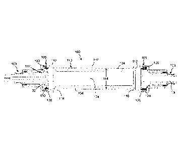
FIG. 1 illustrates a simplified cross-sectional view of an exemplary rotor
assembly 100 having a rotor core barrel 102 cooperated with stub shafts 103,
in
accordance with some embodiments. The rotor core barrel 102 includes a wall
104
extending between lateral ends 106, with the stub shafts secured with the
rotor core
barrel at the lateral ends. The rotor core barrel further includes magnet
receiving area
110 extending along a portion of a length of the rotor core barrel, and
typically along
a majority of the length of the rotor core barrel. The rotor core barrel
further includes
one or more compression bridges 112 each formed in the wall proximate one of
the
lateral ends and separated by a distance, which is typically at least the
length of the
-4-
CA 03016732 2018-09-06
WO 2017/160342
PCT/US2016/053706
magnet receiving area.
FIG. 2 illustrates a simplified cross-sectional view of the rotor core barrel
102
cooperated with the stub shafts 103, in accordance with some embodiments. The
cross-sectional view further illustrates a plurality of magnets 202 positioned
on and
spaced along the wall 104 of the magnet receiving area 110, and typically
between the
compression bridges 112, and about a circumference of the rotor core barrel.
In some
instances, the magnet receiving area 110 may be formed with a smaller diameter
114
or width than at the lateral ends 106 of the rotor core barrel. The reduced
diameter
allows magnets to be cooperated with the rotor core barrel while limiting a
diameter
of the rotor upon final assembly. As introduced above, in some embodiments,
the
magnets 202 are further wrapped with one or more pre-stress wraps 204 that are
wrapped over the plurality of magnets and about the rotor core barrel.
In some implementations, the pre-stress wraps are wrapped about the magnets
along at least a portion of a length of the rotor core barrel between the
compression
bridges 112, and typically about all of the magnets of the array of magnets.
Further,
the one or more wraps can be a fiber, a ribbon, bands, other such elements or
combination of two or more of such elements. For example, in some
implementations, the one or more wraps are ultra-high strength fibers
repeatedly
wrapped around the circumference of the rotor core barrel and the array of
magnets
positioned on the rotor core barrel multiple times while under high tension
force to
induce a compression force on the magnets and the rotor core barrel at least
along the
length of the rotor core barrel where the magnets are positioned. As described
above,
the one or more wraps 204 are ovenvrapped at sufficient force to cause an
inward
radial compressive pre-stress of the wall 104 of the rotor core barrel causing
a
reduction of the diameter 114 of the rotor core barrel at least along a
portion of the
length of the rotor core barrel. The wraps, in part help to affix the magnets
to rotor
core barrel and apply compressive hoop stress at 0 revolutions-per-minute
(rpm). The
compression force further allows for low hoop stresses at high rotation
speeds.
Further, the pre-stressed rotor core barrel can improve a fatigue life of the
rotor
assembly and the generator, motor or other system into which the rotor
assembly is
cooperated. The fiber pre-stress wraps 204 can be made from substantially any
relevant material capable of being wrapped or clamped at the desired force to
achieve
the desired compression force about the magnets 202 and rotor core barrel,
such as but
-5-
CA 03016732 2018-09-06
WO 2017/160342
PCT/US2016/053706
not limited to Kevlar , carbon fiber, fiberglass, other such material, or
combination
of two or more of such wraps.
FIG. 3 illustrates a magnified cross-sectional view of a portion of the rotor
core barrel 102 proximate a lateral end 106 (e.g., a left end as illustrated
in FIG. 1), in
accordance with some embodiments. FIG. 4 illustrates a magnified cross-
sectional
view of a portion of the rotor assembly 100 of FIG. 2, in accordance with some
embodiments. Referring to FIGS. 1-4, in some embodiments the rotor core barrel
102
includes two or more compression bridges 112, with at least one compression
bridge
proximate each lateral end. The compression bridges 112 are radially flexible
structural elements formed proximate the longitudinal ends of the pre-stressed
section
of the rotor core barrel. Further, the compression bridges are configured to
flex or
elastically yield in response to the radial compression deflection of the
portion of the
rotor core barrel under the fiber pre-stress, while preventing rotational and
axial
misalignment between lateral ends and maintaining the bending stiffness of the
rotor
assembly for the intended implementation and rotational speed.
In some embodiments, the compression bridges 112 are formed in the wall
104 at least in part through a reduced thickness 302 of the wall of at least a
portion of
the compression bridge relative to a thickness 304 of the adjacent wall along
the
magnet receiving area 110 and between the compression bridges 112. Further, in
some implementations, the thickness 302 of the wall of at least a portion of
the
compression bridges is less than a thickness 306 of the wall at the lateral
ends 106.
Some embodiments may include one or more boundary extensions 314 that extend
radially away from the extension bridge and the central rotational axis of the
rotor
core barrel proximate one or both side boundaries of the compression bridge.
As
such, in at least some implementations the wall 104 comprises at least
compression
bridges defined by thin regions of the wall and/or two channels
circumferentially
extending about the rotor core barrel.
This reduced thickness 302 of the compression bridges provides for increased
flexibility along the compression bridges. The flexibility of the compression
bridges
limit, as a function of the radial compression deflection enabled by the
compression
bridges, radial expansion deflection of the wall proximate the lateral ends
away from
a central axis of the rotor core barrel that would otherwise be caused by the
radial
deflection of the rotor core barrel along at least the portion of the length
of the rotor
-6-
CA 03016732 2018-09-06
WO 2017/160342
PCT/US2016/053706
core barrel induced by the one or more pre-stress wraps 204. Similarly, during
rotation of the rotor assembly, in some embodiment the compression bridges at
least
in some implementations allow radial expansion of the rotor core barrel at
least along
the magnet receiving area in response to centrifugal force while maintaining
rotational
and axial alignment, rotational stiffness and rotor dynamics of the rotor core
barrel
and rotor assembly.
In some applications, as introduced above, the diameter of the rotor core
barrel
is reduced along at least a portion of the magnet receiving area 110. As such,
the wall
adjacent the compression bridges tapers toward a central axis of the rotor
core barrel.
The tapering of the wall can be at substantially any angle to achieve the
change in
diameter. In some implementations, the wall thickness 304 of the magnet
receiving
area is increased to be greater than a thickness of the compression bridges.
Further, in
some instances, an exterior surface of the wall may include circumferential
shoulders
118 at distal ends of the magnet receiving area 110, which in some instances
define
the boundaries of the magnet receiving area. The thickness 304 of the wall of
the
magnet receiving area is such that it allows radially inward compression in
response
to the one or more fiber pre-stress wraps 204 being wrapped about the magnets
while
still maintaining the structural integrity of the rotor core barrel to
withstand the
intended rotational speeds and induced centrifugal forces. The thicknesses can
depend on the intended implementation of the rotor assembly, including but not
limited to one or more of: intended rotational speed, weight of the rotor core
barrel,
weight of the magnets, type and quantity of fiber wrap, compression force
induced by
the fiber wrap, material of the rotor core barrel, other such factors, and
typically a
combination of two or more of such factors. In some implementations, the rotor
core
barrel is formed of a single material, such as a metal or metallic alloy. For
example,
in some implementations the rotor core barrel is formed from heat treated
steel, or
other such material configured to withstand the rotational forces while
further
enabling the flexing through the compression bridges formed in the wall of the
rotor
core barrel. Typically, the rotor core barrel is further formed from a
ferromagnetic
material.
Still referring to FIGS. 1-4, the stub shafts 103 cooperate with the rotor
core
barrel 102 at the lateral ends 106. In some implementations, multiple bolts
120, pins,
or other such fasteners are utilized to affix the stub shafts with the rotor
core barrel.
-7-
CA 03016732 2018-09-06
WO 2017/160342
PCT/US2016/053706
In some implementations, the bolts thread through a circumferential flange of
each of
the stub shafts to threadedly cooperate with the thicker portion of the wall
at the
lateral ends 106 of the rotor core barrel securing the stub shafts with the
rotor core
barrel. The stub shafts, in some instances, may further include an extended
shoulder
210 that abuts against respective interior edges 310 of the lateral ends 106
of the rotor
core barrel and provides an interference fit. The extended shoulders 210 can
be
configured to aid in providing alignment of the stub shafts with the rotor
core barrel,
and in some implementations in maintaining positioning of the lateral ends
relative to
the stub shafts. In some embodiments, the stub shafts at least partially
extend into a
central cavity 124 of the rotor core barrel.
As introduced above, the flexing of the compression bridges 112 significantly
reduces, and in some instances prevents the radial expansion deflection of the
rotor
core barrel at the lateral ends 106 that may occur as a result of the radial
deflection
induced by the fiber wrap 204. Further, the compression bridges 112 limit
and/or
isolate the radially inward deflection in pre-stressed barrel from stub shafts
103. As
such, the stub shafts and/or the bolts 120 do not have to constrain such
radial
deflection and/or the force associated with any radial deflection is
significantly
reduced. This further maintains the high critical bending speed of the rotor
core
barrel. The compression bridges further concurrently provide high bending
stiffness
for shaft stability.
Some embodiments include one or more lateral restraining fiber wraps 212,
ribbons, clamps or the like that are further circumferentially wrapped or
otherwise
clamped about the rotor core barrel 102 proximate the lateral ends. The stub
shafts
103 are cooperated with and secured with the rotor core barrel prior to the
restraining
wraps 212 being applied to the rotor core barrel. The use of the additional
composite
restraining wrap 212 in affixing the rotor core barrel with the stub shafts
aids in
restraining the lateral ends of the rotor core barrel at intended high
rotational speeds.
The restraining wraps can further inhibit the radial outward deflection of the
lateral
ends of the rotor core barrel that is not inhibited by the compression bridge
112. Still
further, the restraining wraps can further help in maintaining a positioning
of the ends
of the rotor core barrel with the stub shafts (e.g., maintaining the interior
edges 310 of
the lateral ends 106 against the extended shoulder 210 of the stub shafts).
Additionally, the restraining wraps 212 can further help in allowing the bolts
120 to
-8-
CA 03016732 2018-09-06
WO 2017/160342
PCT/US2016/053706
predominantly carry torque loads while limiting or preventing radial loads.
Further, in some implementations, the rotor core barrel 102 includes one or
more restraining wrap grooves or channels 126 extending circumferentially
about the
rotor core barrel proximate each of the lateral ends, and configured to
receive and
position a restraining wrap wrapped about the rotor core barrel. In some
implementations, the restraining wrap grooves are formed between a respective
one of
the lateral ends and one of the compression bridges. One or more extensions
312 can
be included that are separated by a width of the restraining wrap groove 126
and
extend radially away from the central rotational axis of the rotor core
barrel. The
extensions 312 can be formed as part of the wall or can couple with the wall
(e.g.,
through a circular clamp or the like). The depth and/or width of the
restraining wrap
grooves can depend on the type and size of the wrap used for the restraining
wrap
212, amount of wrapping, and other such factors. Similarly, the width of the
restraining wrap groove typically depends on the width of the compression
bridge and
the location of the compression bridge relative to the lateral ends.
The restraining wrap grooves 126 help to locate the restraining wrap and
maintain a position of the restraining wraps about the rotor core barrel as
they are
wrapped about the rotor core barrel. Similar to the fiber wraps 204, the
restraining
wraps 212 can be made from substantially any relevant material capable of
being
wrapped or clamped at the desired force to achieve the desired cOmpression
force
about the rotor core barrel proximate the lateral ends 106 (e.g., Kevlark,
carbon fiber,
fiberglass, etc.).
Still referring to FIGS. 1-4, in some implementations, the rotor assembly 100
is further configured to provide internal cooling of the assembly. In many
applications, the rotor assembly can heat up during use. Often, the composite
pre-
stress wrap 204 limits thermal conduction on the outer diameter of the rotor
core
barrel. As such, it can be advantageous to cool the rotor assembly to achieve
desired
operating rotational speeds while avoiding damage to the rotor assembly. In
some
embodiments, internal cooling is achieved through the flow of air or other
cooling gas
through the rotor core barrel 102.
FIG. 5 illustrates a perspective, cross-sectional view of an exemplary rotor
assembly 100, in accordance with some embodiments. FIG. 6 illustrates a
perspective
end view of an exemplary rotor assembly 100, in accordance with some
embodiments.
-9-
CA 03016732 2018-09-06
WO 2017/160342
PCT/US2016/053706
Referring to FIGS. 1-6, in some embodiments, the rotor core barrel includes a
cavity
124 extending the length of the rotor core barrel and/or the rotor core barrel
is hollow.
The cavity 124 cooperates with one or more inlet cooling conduit 130,
passages, bore,
ducts, channels or the like formed in one of the two stub shafts 103. For
example, in
some implementations, the non-driving end (NDE) stub shaft (illustrated in
FIGS. 1-2
and 5-6 as the right side stub shaft) may include an inlet cooling conduit 130
that
cooperates with the cavity 124 of the rotor core barrel allowing air to flow
through the
inlet cooling conduit and into the cavity. Further in this example, the inlet
cooling
conduit is illustrated as being aligned with the central rotational axis of
the rotor core
barrel. Other embodiments may include one or more inlet cooling conduits that
are
positioned offset from the rotational axis.
The other stub shaft 103 (e.g., a driving end (DE) illustrated in FIGS. 1-2
and
5-6 as the left stub shaft) can be configured to include one or more outlet
cooling
conduits 132, bores, ducts, passages, channels or the like that extend through
a
thickness of the stub shaft with an interior end of each of the cooling bores
interfacing
with the cavity 124 of the rotor core barrel. Air or other coolant gas travels
through
the cavity and exits through the one or more outlet cooling conduits 132. In
some
implementations, the outlet cooling conduits are configured at an angle
relative to
central rotational axis of the rotor core barrel. For example, in some
instances, the
outlet cooling conduits taper such that interior apertures of the outlet
cooling conduits
are closer to the central axis and exterior apertures of the outlet cooling
conduits are
further from the central axis. The angle can vary and in some instances may
depend
on an expected operational rotation speed. Further, in some instances, the
outlet
cooling conduits may be curved and/or angled relative to an expected direction
of
travel to further enhance the air flow.
The air flow, indicated in the exemplary embodiment by arrow 502 in FIG. 5,
flows from the inlet cooling conduit 130 along the length of the cavity 124 of
the rotor
core barrel 102 to exit through the outlet cooling conduits 132. The
cooperation
between the inlet cooling conduit, the configuration of the outlet cooling
conduits, and
the rotation and centrifugal force of rotation of the rotor assembly induces
the air flow
into the inlet cooling conduit, along the cavity and exits through the outlet
cooling
conduits. In implementations, the rotation of the rotor core barrel draws air
through
the inlet cooling conduit of the second stub shaft, along the cavity and out
of the
-10-
CA 03016732 2018-09-06
WO 2017/160342
PCT/US2016/053706
multiple outlet cooling conduits decreasing an internal temperature of at
least the rotor
core barrel.
Accordingly, the cooling operates in concert with the pre-stress wrap to
reduce
the heat that may be conducted through the pre-stress wraps and/or the thermal
conduction that may be limited by least the pre-stress wraps. Additionally,
the
rotation of the rotor core barrel in cooperation with the coolant or cooling
airflow
paths through the cavity of the rotor core barrel and the outlet cooling
conduits creates
pressure gradients to cause the airflow through the rotor core barrel. As
such, the
cooling airflow is achieved without the additional complexity of adding a fan
or
blower to the system.
FIG. 7 illustrates a simplified flow diagram of a process 700 of constructing
and/or assembling a rotor assembly 100, in accordance with some embodiments.
In
step 702, a rotor core barrel 102 is cooperated at each of two lateral ends
106 with one
of two stub shafts 103 with each of the two stub shafts being cooperated with
and
secured with the rotor core barrel at the lateral ends. The rotor core barrel
comprises a
wall 104 extending between the lateral ends and at least two compression
bridges 112
each formed in the wall proximate one of the lateral ends and separated by a
distance.
In some implementations, the rotor core barrel further includes the magnet
receiving
area 110 positioned between two compression bridges. Additionally, in some
instances, rotor core barrel has a step at each end of the magnet receiving
area such
that a diameter of the rotor core barrel is less along the magnet receiving
area than a
diameter at the lateral ends. The rotor core barrel is further formed with a
first
thickness defining at least a portion of the compression bridges, and at least
a second
thickness adjacent to each compression bridge and between the compression
bridges.
The second thickness is greater than the first thickness. In some embodiments,
at
least two channels or grooves are formed in the wall that extend
circumferentially
about the rotor core barrel defining the at least two compression bridges. The
channels, in some implementations, are formed from a recess or depression in
the wall
that extends about the circumference of the rotor core barrel. In some
embodiments,
the channel has a rectangular cross-section. Other implementations, however,
may
utilize one or more channels with different cross-sectional shapes, such as
but not
limited to semi-circular, semi-oval, triangular, or other such shapes to
achieve a
desired deflection through the compression bridges. Similarly, the bottom or
floor of
-11-
CA 03016732 2018-09-06
WO 2017/160342
PCT/US2016/053706
the compression bridge may include multiple relatively small semi-circular,
triangular
or other such grooves that extend circumferentially about the rotor core
barrel and
parallel with the compression bridge.
In step 704, an array of a plurality of magnets is cooperated on and spaced
along and circumferentially about the wall of a rotor core barrel between two
compression bridges located proximate lateral ends of the rotor core barrel.
Again,
the magnets are typically positioned along and about the magnet receiving
area. In
some instances, the magnets are equally distributed about the circumference of
the
rotor core barrel. The type, number, size, strength of magnetic field, and
other such
characteristics of one or more of the magnets can vary depending on one or
more
factors, such as an intended implementation of the rotor assembly.
In step 706, one or more pre-stress wraps are wrapped over the plurality of
magnets and about the rotor core barrel along at least a portion of a length
of the rotor
core barrel between the compression bridges. The pre-stress wraps are wrapped
at a
pressure that induces a radial compression deflection of the wall of the rotor
core
barrel at least along the portion of the length of the rotor core barrel.
In step 708, radial compression deflection is enabled through the compression
bridges, induced by the one or more pre-stress wraps, of the wall of the rotor
core
barrel at the compression bridges relative to the wall of the rotor core
barrel proximate
the lateral ends. Further, some embodiments limit, as a function of the radial
compression deflection enabled by the compression bridges, radial expansion
deflection of the wall proximate the lateral ends away from a central axis
that would
otherwise be caused by the radial compression deflection of the rotor core
barrel along
the at least the portion of the length of the rotor core barrel induced by the
one or
more pre-stress wraps.
In some embodiments, the rotor core barrel is further configured with at least
two restraining wrap grooves 126 that are form in the wall 104. At least one
restraining wrap groove each extends circumferentially about the rotor core
barrel
proximate each of the lateral ends. At least one restraining wrap is wrapped
one or
more times about the circumference of the rotor core barrel and within each of
the
restraining wrap grooves, wherein the restraining wrap grooves are configured
to
receive and position the restraining wrap wrapped about the rotor core barrel
proximate each of the lateral ends. The wrapping of the restraining wraps
about the
-12-
CA 03016732 2018-09-06
WO 2017/160342
PCT/US2016/053706
wall of the rotor core barrel proximate each of the lateral ends induces a
radially
compression force and inhibits radial expansion deflection of the wall 104 at
the later
ends away from a central axis of the rotor core barrel.
As described above, some embodiments are configured to provide a cooling of
the rotor assembly. In some implementations, a first stub shaft (e.g., a drive
end) is
formed with multiple outlet cooling conduits that interface at an interior end
with the
one or more cavities 124 of the rotor core barrel when the stub shaft is
secured with
the rotor core barrel. The outlet cooling conduits extend through the stub
shaft to
provide airflow out of the cavity. A second stub shaft (e.g., the non-drive
end) can be
configured with one or more inlet cooling conduits that extend through a
thickness of
the second stub shaft and provide an inflow of air into the cavity. In some
implementations, an inlet cooling conduit is formed to align with a central
rotational
axis of the second stub shaft and extends the length of the second stub shaft.
In some embodiments, a first stub shaft (e.g., a non-drive end stub shaft) can
be cooperated with a first lateral end of the rotor core barrel such that an
interior end
of each of one or more outlet cooling conduits 132 extending through a
thickness of
the first stub shaft communicates with at least one cavity 124 extending
through a
length of the rotor core barrel. In some instances, the outlet cooling
conduits are
formed through a shoulder of the stub shaft that radially extends from a
central shaft
of the stub shaft. A second stub shaft (e.g., a drive end stub shaft) can be
cooperated
with a second lateral end of the rotor core barrel such that an inlet cooling
conduit
formed in the second stub shaft communicates with at least one cavity 124 of
the rotor
core barrel. The cooperation of the inlet cooling conduit and the outlet
cooling
conduits with the cavity 124 establishes a coolant flow path through the inlet
cooling
conduit of the second stub shaft, along the at least one cavity and out of the
multiple
outlet cooling conduits enabling coolant flow in response to rotation of the
rotor core
barrel to decrease an internal temperature of at least the rotor core barrel.
In some
implementations, causing the rotor core barrel and array of magnets to rotate
causes
air to be drawn through an inlet cooling conduit 130 of a second stub shaft,
along the
hollow cavity 124 of the rotor core barrel extending along the length of the
rotor core
barrel, and expelling the air drawn in out of multiple outlet cooling conduits
132
formed in the second stub shaft.
Some embodiments provided rotor assemblies, comprising: a rotor core barrel
-13-
CA 03016732 2018-09-06
WO 2017/160342
PCT/US2016/053706
comprising a wall extending between lateral ends, and at least two compression
bridges each formed in the wall proximate one of the lateral ends and
separated by a
distance; an array of a plurality of magnets positioned on and spaced along
the wall
between the compression bridges and about a circumference of the rotor core
barrel;
and one or more pre-stress wraps wrapped over the plurality of magnets and
about the
rotor core barrel along at least a portion of a length of the rotor core
barrel between
the compression bridges, wherein the compression bridges enable radial
compression
deflection, induced by radial compression of the a rotor core barrel by the
one or more
pre-stress wraps, of the wall of the rotor core barrel at the compression
bridges
relative to the wall of the rotor core barrel proximate the lateral ends.
Further some embodiments provide methods of constructing rotor assemblies,
comprising: cooperating a rotor core barrel at each of two lateral ends with
one of two
stub shafts each cooperated with and secured with the rotor core barrel at the
lateral
ends, wherein the rotor core barrel comprises a wall extending between the
lateral
ends and at least two compression bridges each formed in the wall proximate
one of
the lateral ends and separated by a distance; cooperating an array of a
plurality of
magnets on and spaced along and circumferentially about a wall of a rotor core
barrel
between two compression bridges located proximate lateral ends of the rotor
core
barrel; \\Tapping one or more pre-stress wraps over the plurality of magnets
and about
the rotor core barrel along at least a portion of a length of the rotor core
barrel
between the compression bridges, at a pressure inducing a radial compression
deflection of the wall of the rotor core barrel at least along the portion of
the length of
the rotor core barrel; and enabling through the compression bridges the radial
compression deflection, induced by the one or more pre-stress wraps, of the
wall of
the rotor core barrel at the compression bridges relative to the wall of the
rotor core
barrel proximate the lateral ends.
While the invention herein disclosed has been described by means of specific
embodiments, examples and applications thereof, numerous modifications and
variations could be made thereto by those skilled in the art without departing
from the
scope of the invention set forth in the claims.
-14-