Note: Descriptions are shown in the official language in which they were submitted.
I
HANDRAIL WALL MOUNT ADAPTER
=
TECHNICAL FIELD
The technical field generally relates to handrails, and more precisely to
wall mount adapters for handrail wall mounting brackets.
BACKGROUND
Handrails are adapted to be grasped by the hand of a user to provide
1,0 stability or support to the user. Handrails are commonly used on
stairways, but
can also be used in leveled areas such as along a corridor.
When the handrail is disposed along a wall, the handrail is usually
mounted to the wall by a generally L-shaped bracket which connects to the
underside of the handrail to allow a hand of the user to grip the handrail
from
above.
When mounting the handrail to the wall, the user may want to position the
handrail at a certain distance from the wall, or may be required to do so by
local
legislation. For example, local legislation may require the handrail to be at
a
minimum distance of 38 mm from the wall. According to other legislation, the
handrail may be required to be at a minimum distance of 57 mm from the wall.
Once the handrail is installed to the wall, the user may want to move the
handrail away from the wall, to conform to a change in legislation for
example, or
to replace the handrail with a handrail with different dimensions. In this
case, the
user would unfortunately have to replace all of the brackets with brackets of
.. different dimensions.
Furthermore, the wall surface to which the handrail is mounted may not be
even. For example, certain features of the wall may create depressions on the
wall surface, thereby creating the need for different brackets with different
dimensions to support the handrail along its entire length, which creates
additional costs for the user and for the manufacturer.
CA 3017159 2018-09-12
2
In some cases, the bracket may also be adapted to receive screws such
as decorative screws which may not be sufficiently strong to properly secure
the
bracket to the wall. In these cases, the user may use additional securing
fasteners such as toggle bolts, wall anchors, expansion bolts, lag bolts,
masonry
screws or the like to secure the bracket, which would detract from the
appearance of the brackets and/or handrail if left exposed.
There is therefore a need for a device which would overcome at least one
of the above-identified drawbacks.
SUMMARY
According to one aspect, there is provided a handrail wall mount adapter
for mounting a handrail wall mounting bracket of a handrail assembly to a
wall,
the bracket including a mounting plate having a plurality of mounting openings
extending therethrough, the adapter comprising: a body having a front face
configured for matingly receiving the mounting plate and a rear face for
abutting
the wall, the body further having at least one unthreaded opening extending
between the front face and the rear face of the body, each unthreaded opening
being configured for receiving a wall mounting fastener therethrough, the body
further having a plurality of bracket mounting openings defined in the front
face
for receiving at least one bracket mounting fastener, the body being
selectively
positionable relative to the mounting plate in a first orientation in which
the at
least one unthreaded opening is aligned with the mounting openings of the
mounting plate to allow the mounting fasteners to extend through the mounting
openings and through the unthreaded openings and securely engage the wall,
and in a second orientation in which the bracket mounting openings are aligned
with the mounting openings of the mounting plate to allow the bracket mounting
fasteners to extend through the mounting openings and the bracket mounting
openings to thereby secure the mounting bracket to the adapter.
In one embodiment, each bracket mounting opening includes a threaded
bore to threadably receive the bracket mounting screws.
CA 3017159 2018-09-12
3
In one embodiment, the first, second and third bracket mounting bores are
unthreaded and the bracket mounting screws include self-tapping screws.
In one embodiment, the at least one unthreaded opening includes a
plurality of offcentered unthreaded holes disposed around a center of the
front
face.
In one embodiment, the plurality of offcentered unthreaded holes includes
first, second and third offcentered unthreaded holes.
In one embodiment, the at least one unthreaded opening includes a
central unthreaded hole centered on the front face.
In one embodiment, the first, second and third offcentered unthreaded
holes have the same diameter and the central unthreaded hole has a diameter
larger than the diameter of the offcentered unthreaded holes.
In one embodiment, each unthreaded opening is counterbored.
In one embodiment, each unthreaded opening includes a cylindrical
recess extending from the front face towards the rear face and a bore
extending
from the cylindrical recess towards the rear face.
In one embodiment, the body further includes a front recess which extends
into the body from the front face towards the rear face and which defines a
front
peripheral edge surrounding the front recess, the front recess being sized and
shaped to receive the mounting plate.
In one embodiment, the body further includes a body sidewall extending
between the front and rear faces, the body sidewall being tapered from the
rear
face towards the front face.
In one embodiment, the body is hollow.
In one embodiment, the front face of the body is closed and the rear face
is open.
In one embodiment, the body further includes a rear peripheral edge
facing away from the front face for abutting the wall.
CA 3017159 2018-09-12
4
In one embodiment, the body further includes a rear lip extending along
the inside of the body sidewall near the rear peripheral edge, the rear lip
being
configured for abutting a front peripheral edge of an additional adapter to
allow
the adapter to be stacked over the additional adapter.
In one embodiment, the body is rectangular.
According to another aspect, there is also provided a kit for mounting a
handrail wall mounting bracket of a handrail assembly to a wall, the bracket
including a mounting plate having a plurality of mounting openings extending
therethrough, the kit comprising: a first handrail wall mount adapter as
described
above; and a second handrail wall mount adapter as described above, the
second adapter being selectively stackable over the first adapter such that
the
rear face of the second handrail wall mount adapter engages the front face of
the
first handrail wall mount adapter and each unthreaded openings of the second
handrail wall mount adapter is aligned with a corresponding bracket mounting
opening of the first handrail wall mount to receive a corresponding adapter
mounting screw therethrough.
In one embodiment, the body of each one of the first and second handrail
wall mount adapters further includes a body sidewall extending between the
front
and rear faces of the corresponding body, the body sidewall being tapered from
the rear face towards the front face.
In one embodiment, the body of the second handrail wall mount adapter
includes a rear peripheral edge facing away from the front face for abutting
the
wall and a rear lip extending along the inside of the body sidewall near the
rear
peripheral edge, the rear lip being configured for abutting a front peripheral
edge
of the first handrail wall mount adapter.
According to yet another aspect, there is also provided a handrail wall
mount adapter for mounting a handrail wall mounting bracket of a handrail
assembly to a wall, the bracket including a mounting plate having a plurality
of
mounting openings adapted to receive mounting fasteners therethrough, the
adapter comprising: a body having a front face configured for matingly
receiving
CA 3017159 2018-09-12
5
the mounting plate and a rear face for abutting the wall, the body being
positionable relative to the mounting plate in a first portion and a second
position,
the body further having: at least one unthreaded opening extending between the
front face and the rear face of the body for receiving the mounting fasteners
therethrough, the at least one unthreaded opening being disposed on the body
such that when the adapter is in a first orientation relative to the mounting
plate,
the at least one unthreaded opening is aligned with the mounting openings of
the
mounting plate to allow the mounting fasteners to extend through the mounting
openings and through the unthreaded openings and securely engage the wall;
and a plurality of bracket mounting openings defined in the front face for
receiving at least one bracket mounting fastener, the bracket mounting
openings
being disposed on the body such that when the adapter is in a second
orientation
relative to the mounting plate, the bracket mounting openings are aligned with
the
mounting openings of the mounting plate to allow the bracket mounting
fasteners
to extend through the mounting openings and the bracket mounting openings to
thereby secure the bracket to the adapter.
BRIEF DESCRIPTION OF THE DRAWINGS
For a better understanding of the embodiments described herein and to
show more clearly how they may be carried into effect, reference will now be
made, by way of example only, to the accompanying drawings which show at
least one exemplary embodiment, and in which:
FIG. 1 is a top front perspective view of a handrail wall mount adapter, in
accordance with one embodiment, with the adapter connected to a handrail wall
mount bracket and shown in a first configuration in which the adapter is
adapted
to be connected to a wall using two upper wall mounting fasteners and one
lower
wall mounting fastener;
FIG. 2 is a top rear perspective view of the handrail wall mount adapter
illustrated in FIG. 1, with the adapter still connected to the handrail wall
mount
bracket and still shown in the first configuration;
CA 3017159 2018-09-12
6
FIG. 3 is a top front perspective view of the handrail wall mount adapter
illustrated in FIG. 1, with the adapter shown in isolation;
FIG. 4 is a top rear front perspective view of the handrail wall mount
adapter illustrated in FIG. 1;
FIG. 5 is a front elevation view of the handrail wall mount adapter
illustrated in FIG. 1;
FIG. 6 is a rear elevation view of the handrail wall mount adapter
illustrated in FIG. 1;
FIG. 7 is a top plan view of the handrail wall mount adapter illustrated in
FIG. 1;
FIG. 8A is a side elevation view of the handrail wall mount adapter
illustrated in FIG. 1;
FIG. 8B is a cross-section view of the handrail wall mount adapter
illustrated in FIG. 1;
FIG. 9 is a top front perspective view of the handrail wall mount adapter
illustrated in FIG. 1, with the adapter connected to a handrail wall mount
bracket
and shown in a second configuration in which the adapter is adapted to be
connected to a wall using one upper wall mounting fastener and two lower wall
mounting fasteners;
FIG. 10 is a top rear perspective view of the handrail wall mount adapter
illustrated in FIG. 9, with the adapter still connected to the handrail wall
mount
bracket and still shown in the second configuration;
FIG. 11 is a top front perspective view of the handrail wall mount adapter
illustrated in FIG. 1, with the adapter connected to a handrail wall mount
bracket
and shown in a third configuration in which the adapter is adapted to be
connected to a wall using a single central wall mounting fastener;
CA 3017159 2018-09-12
7
FIG. 12 is a top rear perspective view of the handrail wall mount adapter
illustrated in FIG. 11, with the adapter still connected to the handrail wall
mount
bracket and still shown in the third configuration;
FIG. 13 is a top front perspective view of a first and second handrail wall
mount adapters similar to the handrail wall mount adapter illustrated in FIG.
1,
with the second adapter mounted between the first adapter and a handrail wall
mount bracket and with the first adapter in the first configuration
illustrated in FIG.
1 and the second adapter in the second configuration illustrated in FIG. 9;
FIG. 14 is a top rear perspective view of the first and second handrail wall
mount adapters illustrated in FIG. 13;
FIG. 15 is a cross-section view, taken along line XV-XV, of the first and
second handrail wall mount adapters illustrated in FIG. 13; and
FIG. 16 is another cross-section view, taken along line XVI-XVI, of the first
and second handrail wall mount adapters illustrated in FIG. 13.
It will be appreciated that for simplicity and clarity of illustration,
elements
shown in the figures have not necessarily been drawn to scale. For example,
the
dimensions of some of the elements may be exaggerated relative to other
elements for clarity.
DETAILED DESCRIPTION
Although the embodiments of the handrail wall mount adapter and
corresponding parts thereof consist of certain geometrical configurations as
explained and illustrated herein, not all of these components and geometries
are
essential and thus should not be taken in their restrictive sense. It is to be
understood, as also apparent to a person skilled in the art, that other
suitable
components and cooperation thereinbetween, as well as other suitable
geometrical configurations, may be used for the handrail wall mount adapter,
as
will be briefly explained herein and as can be easily inferred herefrom by a
person skilled in the art.
CA 3017159 2018-09-12
8
Moreover, it will be appreciated that positional descriptions such as "front",
"rear", "top", "bottom" and the like should be taken in the context of the
figures
only and should not be considered limiting. More particularly, they correspond
to
the position and orientation of the handrail wall mounting bracket, when
mounted
such that it supports a handrail from the underside of the handrail to allow a
hand
of a user to grab the handrail generally from above the handrail and slide
longitudinally along the handrail substantially unimpeded. The rear position
corresponds to portions adjacent the wall while the front position corresponds
to
portions opposed to the wall.
Having discussed the general context of the handrail wall mount adapter,
optional embodiments will be discussed further hereinbelow. The embodiments
according to the following description are given for exemplification purposes
only.
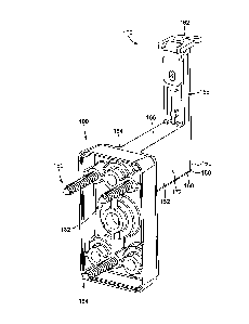
Referring first to FIGS. 1 and 2, there is provided a handrail wall mount
adapter 100, in accordance with one embodiment. The adapter 100 is configured
to attach a handrail wall mounting bracket 150 to a wall. The handrail wall
mounting bracket 150 is adapted to support a handrail and to maintain the
handrail spaced from the wall such that a user may readily grab and/or hold
the
handrail.
In the embodiment illustrated in FIGS. 1 and 2, the bracket 150 is
generally L-shaped and includes a generally horizontal first elongated portion
152
having a first end 154 and a second end 156 and a generally vertical second
elongated portion 158 having a first end 160 secured to the second end 156 of
the first elongated portion 152 and a second end 162 adapted to be secured to
the underside of the handrail.
The bracket 150 further includes a mounting plate 164 secured to the first
end 154 of the first elongated portion 152. The mounting plate 164 is adapted
to
be placed against and fastened to the adapter 100 to secure the bracket 150 to
the adapter 100. Specifically, the mounting plate 164 is generally planar and
extends generally vertically and orthogonally to the first elongated portion
152 of
the bracket 150.
CA 3017159 2018-09-12
9
In the illustrated embodiment, both the mounting plate 164 and the
adapter 100 are generally rectangular. Alternatively, the mounting plate 164
and
the adapter 100 could have a different shape. It will also be understood that
although the mounting plate 164 and the adapter 100 are shown in FIGS. 1 and 2
as having the same shape, the mounting plate 164 and the adapter 100 could
instead be shaped differently from each other.
Still in the illustrated embodiment, the first elongated portion 152 of the
bracket 150 has a generally rectangular cross-section. Specifically, the first
elongated portion 152 includes top and bottom walls 166, 168 which are
disposed generally horizontally and parallel to each other, and first and
second
side walls 170, 172 which are disposed generally vertically and parallel to
each
other. Still in the illustrated embodiment, the side walls 170, 172 are longer
than
the top and bottom walls 166, 168, such that the cross-section of the first
elongated portion 152 is vertically elongated. It will be understood that this
configuration helps prevent the first elongated portion 152 from bending
downwardly when a user grabbing the handrail puts his weight down on the
handrail. Alternatively, instead of being rectangular, the cross-section of
the first
elongated portion 152 may instead be circular, oval or have any other shape
which a skilled person would consider to be appropriate.
In the illustrated embodiment, the first and second elongated portions 152,
158 of the bracket 150 are angled away from each other at an angle of about 90
degrees. Alternatively, the first and second elongated portions 152, 158 could
be
disposed at a different angle from each other. Specifically, the first
elongated
portion 152 may not be exactly horizontal and/or the second elongated portion
158 may not be exactly vertical.
Still in the illustrated embodiment, the mounting plate 164 includes a top
left mounting opening or hole 174 disposed to the left of the first elongated
portion 152, a top right mounting opening or hole 176 disposed to the right of
the
first elongated portion 158 and a bottom mounting opening or hole 178 which is
located below the first elongated portion 152 and which is generally
horizontally
CA 3017159 2018-09-12
10
centred on the mounting plate 164. Alternatively, the mounting plate 164 could
include a different number of holes and/or the holes could be positioned at
different locations on the mounting plate 164.
The handrail wall mount adapter 100 is adapted to allow the bracket 150
to be mounted to a wall, not shown, in one of multiple configurations, each
configuration using a certain number and/or type of fasteners, as will be
further
explained below. In the embodiment illustrated in FIGS. 1 and 2, the adapter
100
and the bracket 150 are configured to be mounted to the wall using a top left
wall
mounting fastener 180 engaging the top left mounting hole 174 of the mounting
plate 164, a top right wall mounting fastener 182 engaging the top right
mounting
hole 176 and a bottom wall mounting fastener 184 engaging the bottom mounting
hole 178.
In one embodiment, the top left, top right and bottom mounting holes 174,
176, 178 of the mounting plate 164 are countersunk and the fasteners 180, 182,
184 include countersunk screws having a conical head which are sized and
shaped to be received snuggly within the countersunk holes. Alternatively, the
mounting holes 174, 176, 178 of the mounting plate 164 could have a different
configuration.
Now turning to FIGS. 3 to 8B, the adapter 100 includes a rectangular body
300 with generally rounded corners. The body 300 includes a front face 310, a
rear face 402 spaced from the front face 310 and a body sidewall 301 extending
between the front and rear faces 310, 402. More specifically, the body
sidewall
301 includes a first horizontal wall 302, a second horizontal wall 304 spaced
from
the first horizontal wall 302, a first vertical side wall 306 and a second
vertical
.. side wall 308 spaced from the first vertical side wall 306.
In the illustrated embodiment, the body 300 is generally hollow and
defines an inner cavity 400 which is open on one side. Specifically, the front
face
310 is closed and the rear face 402 is open. The body 300 further includes a
front
recess 312 which extends into the body 300 from the front face 310 towards the
rear face 402 and a front peripheral edge 314 surrounding the front recess
312.
CA 3017159 2018-09-12
11
The front recess 312 is sized and shaped to receive the mounting plate 164 of
the bracket 150. In the illustrated embodiment, the front recess 312 and the
front
peripheral edge 314 are rectangular to receive the mounting plate 164 which is
also rectangular. Alternatively, the front recess 312 and the front peripheral
edge
314 may have another shape corresponding to the shape of the mounting plate
164.
At the rear face 402, the first horizontal wall 302, the second horizontal
wall 304, the first vertical side wall 306 and the second vertical side wall
308
define a rectangular rear peripheral edge 404 which faces rearvvardly, away
from
the front face 310, and which is adapted to abut the wall to which the
handrail is
secured.
It will be appreciated that this configuration allows the body 300 to be
manufactured by molding using a moldable material such as a plastic or a die-
castable metal such as zinc, aluminium or the like. Alternatively, the body
300
could instead be solid and be manufactured by machining from a metal, for
example, in which case the body 300 may include a closed rear face.
In the illustrated embodiment, the body sidewall 301 is tapered from the
rear face 402 towards the front face 310. Specifically, the first horizontal
wall 302
and the second horizontal wall 304 are not disposed in planes which are
parallel
to each other, but are instead angled towards a center of the front face 310.
Similarly, the first vertical side wall 306 and the second vertical side wall
308 are
also not disposed in planes which are parallel to each other, but are instead
also
angled towards a center of the front face 310. More specifically, the first
horizontal wall 302 is angled towards the second horizontal wall 304, from the
rear face 402 towards the front face 310, and the second horizontal wall 304
is
angled towards the first horizontal wall 302, from the rear face 402 towards
the
front face 310. Similarly, the first vertical side wall 306 is angled towards
the
second vertical side wall 308 and the second vertical side wall 308 is angled
towards the first vertical side wall 306, again from the rear face 402 towards
the
front face 310.
CA 3017159 2018-09-12
12
It will be understood that in this configuration, the front peripheral edge
314 therefore defines a smaller rectangle than the rear peripheral edge 404,
which allows the adapter 100 to be stacked over a second, similar adapter, as
will be further explained below.
Still in the illustrated embodiment, the body 300 further includes a
rectangular rear lip 406 which extends along the inside of the first
horizontal wall
302, of the second horizontal wall 304, of the first vertical side wall 306
and of the
second vertical side wall 308, near the rear peripheral edge 404. The rear lip
406
is adapted to abut the front peripheral edge 314 of a second, similar adapter
when the adapter 100 is stacked over the second, similar adapter, as will be
explained further below. Alternatively, in an embodiment in which the rear
face
402 is closed instead of being open, the body 300 could instead include a rear
recess which would be generally similar to the front recess 312 and which
would
extend into the body 300 from the rear face 402 towards the front face 310.
Still referring to FIGS. 3 to 8B, the body 300 further includes plurality of
bores or holes 316a, 316b, 316c extending through the body 300 perpendicularly
to the front face 310. In the illustrated embodiment, the holes 316a, 316b,
316c
are generally offcentered relative to the front face 310. In other words, the
holes
316a, 316b, 316c are generally disposed around a center of the front face 310.
More specifically, the plurality of bores includes a first counterbored hole
316a
which is located generally towards the first horizontal wall 302 and the first
vertical side wall 306, a second counterbored hole 316b which is located
generally towards the first horizontal wall 302 and the second vertical side
wall
308 and a third counterbored hole 316c which is located generally towards the
second horizontal wall 304 and which is generally centered horizontally
between
the first and second vertical side walls 306, 308.
As best shown in FIG. 8B, each counterbored hole 316a, 316b, 316c
includes a cylindrical recess 800 extending from the front face 310 towards
the
rear face 402 of the adapter 100 and a bore 802 extending from the cylindrical
recess 800 away from the front face 310 and towards the rear face 402. The
CA 3017159 2018-09-12
13
cylindrical recess 800 is adapted to receive a head of the corresponding
fastener
and the bore 802 is adapted to receive a body of the fastener.
In the illustrated embodiment, the bore 802 is unthreaded to allow the
corresponding fastener to simply extend therethrough and engage the wall
against which the adapter 100 is placed.
Referring back to FIGS. 1 and 2, the adapter 100 is shown ready to be
mounted to the wall in a first configuration, in which the adapter 100 is
positioned
and oriented such that the first vertical side wall 306 is disposed to the
left of the
second vertical side wall 308 and the first horizontal wall 302 is disposed
above
the second horizontal wall 304.
In the illustrated embodiment, the first, second and third counterbored
holes 316a, 316b, 316c are further positioned on the front face 310 such that,
in
this orientation, they are in alignment respectively with the top left, top
right and
bottom mounting holes 174, 176, 178 of the mounting plate 164 when the
.. mounting plate 164 is received in the front recess 312.
In this first configuration, each one of the left, right and bottom fasteners
180, 182, 184 includes a screw which passes through a corresponding one of the
top left, top right and bottom mounting holes 174, 176, 178 of the mounting
plate
164 and through a corresponding one of the top left, top right and bottom
counterbored holes 316a, 316b, 316c of the body 300 to engage the wall and
thereby secure the handrail to the wall.
To mount the bracket 150, and therefore the handrail, to the wall in this
first configuration, the bracket 150 is first placed over the adapter 100 such
that
the mounting plate 164 is received in the front recess 312 of the adapter 100.
The adapter 100 is then positioned on the wall in a desired location in which
the
bracket 150 extends to and can be connected to the underside of the handrail.
The fasteners 180, 182, 184 are then inserted in their respective holes of
the mounting plate 164 until the head of the fastener 180, 182, 184 abuts the
mounting plate 164 to firmly secure the adapter 100 against the wall and the
CA 3017159 2018-09-12
14
mounting plate 164 of the bracket 150 against the adapter 100. It will be
appreciated that in this configuration, both the adapter 100 and the bracket
150
are secured to the wall using only the three fasteners 180, 182, 184.
Referring again to FIGS. 3 to 8B, the body 300 of the adapter 100 further
includes a first bracket mounting opening or bore 318a located generally
towards
the first horizontal wall 302 and horizontally between the first and second
counterbored holes 316a, 316b, a second bracket mounting opening or bore
318b located near the second horizontal wall 304 and horizontally between the
first vertical side wall 306 and the third counterbored hole 316c and a third
bracket mounting opening or bore 318c located near the second horizontal wall
304 and horizontally between the third counterbored hole 316c and the second
vertical side wall 308. The first, second and third bracket mounting bores
318a,
318b, 318c are disposed generally orthogonally to the front face 310 and
therefore parallel to the first, second and third counterbored holes 316a,
316b,
316c.
In the illustrated embodiment, the first, second and third bracket mounting
bores 318a, 318b, 318c extend all the way through the body 300 between the
front face 310 and the rear face 402. Alternatively, the first, second and
third
bracket mounting bores 318a, 318b, 318c may be blind such that they only
extend partially through the body 300 from the front face 310 towards the rear
face 310.
Now referring to FIGS. 9 and 10, the adapter 100 is shown assembled
with the bracket 150 in a second configuration, in which the adapter is
rotated
180 degrees from the first configuration illustrated in FIGS. 1 and 2.
Specifically,
the adapter 100 is positioned and oriented such that the first vertical side
wall
306 is disposed to the right of the second vertical side wall 308 and the
first
horizontal wall 302 is disposed below the second horizontal wall 304.
In the illustrated embodiment, the third, second and first bracket mounting
bores 318c, 318b, 318a are further positioned on the front face 310 such that,
in
this orientation, they are in alignment respectively with the top left, top
right and
CA 3017159 2018-09-12
15
bottom mounting holes 174, 176, 178 of the mounting plate 164 when the
mounting plate 164 is received in the front recess 312.
In this configuration, the adapter 100 can first be positioned and secured
on the wall. Specifically, the first, second and third counterbored holes
316a,
316b, 316c are adapted to respectively receive first, second and third wall
mounting screws 900, 902, 904, which can be similar to the left, right and
bottom
fasteners 180, 182, 184 used with the adapter 100 in the first configuration
or
which could be shorter.
The adapter 100 is first placed in abutment against the wall at a desired
location, and the first, second and third wall mounting screws 900, 902, 904
are
inserted into the counterbored holes 316a, 316b, 316c and into the wall beyond
the adapter 100 until the head of the screws 900, 902, 904 abuts the adapter
100
and the body of the screws 900, 902, 904 firmly engages the wall, thereby
securing the adapter 100 to the wall.
Once the adapter 100 has been secured to the wall, the bracket 150 can
then be placed over the adapter 100 such that the mounting plate 164 is
received
in the front recess 312 of the adapter 100. As explained above, in this
position,
the top left, top right and bottom mounting holes 174, 176, 178 of the
mounting
plate 164 are aligned respectively with the third, second and first bracket
mounting bores 318c, 318b, 318a of the adapter 100.
The bracket 150 can then be secured to the adapter 100 using first,
second and third bracket mounting screws 950, 952, 954, which are adapted to
pass through the top left, top right and bottom mounting holes 174, 176, 178
of
the mounting plate 164 and to threadably engage the third, second and first
bracket mounting bores 318c, 318b, 318a of the adapter 100.
It will be appreciated that since the bracket mounting screws 950, 952,
954 only secure the bracket 150 to the adapter 100, the bracket mounting
screws
950, 952, 954 do not need to extend beyond the adapter 100 and can therefore
be substantially shorter than the wall mounting screws 900, 902, 904 and the
fasteners 180, 182, 184 used with the adapter in the first embodiment
illustrated
CA 3017159 2018-09-12
16
in FIGS. 1 and 2. Alternatively, the bracket mounting screws 950, 952, 954
could
extend beyond the adapter 100 and engage the wall to further secure the
bracket
150 and the adapter 100 to the wall.
It will be appreciated that this second configuration allows the user to first
.. position the adapter 100 on the wall in a desired or required location, and
then
secure the handrail to the adapter 100 in a separate operation.
In one embodiment, the first, second and third bracket mounting bores
318a, 318b, 318c are threaded to threadably receive the bracket mounting
screws 950, 952, 954. Alternatively, instead of the first, second and third
bracket
.. mounting bores 318a, 318b, 318c being threaded, the first, second and third
bracket mounting bores 318a, 318b, 318c could be unthreaded and the bracket
mounting screws 950, 952, 954 could be self-tapping screws. Specifically, the
body 300 could be made of a material adapted to receive self-tapping screws,
such as a plastic, and the self-tapping screws could be sized and shaped to
create threads in the unthreaded first, second and third bracket mounting
bores
318a, 318b, 318c as the bracket mounting screws 950, 952, 954 are screwed
into their respective bore to thereby secure the bracket 150 to the adapter
100.
Referring back once again to FIGS. 3 to 8B, the body 300 further includes
a central counterbored hole 350 generally centered on the front face 310 and
extending through the front face 310. As shown more precisely in FIG. 8B, the
central counterbored hole 350 is generally similar to the first, second and
third
counterbored holes 316a, 316b, 316c, albeit slightly larger. Specifically, the
central counterbored hole 350 includes a cylindrical recess 850 extending from
the front face 310 towards the rear face 402 of the adapter 100 and a bore 852
extending from the cylindrical recess 850, away from the front face 310.
Turning now to FIGS. 11 and 12, the adapter 100 is shown assembled
with the bracket 150 and the adapter 100 is shown ready to be mounted to the
wall in a third configuration. In this third configuration, the adapter 100 is
oriented
similarly to the second configuration, with the first vertical side wall 306
disposed
CA 3017159 2018-09-12
17
to the right of the second vertical side wall 308 and the first horizontal
wall 302
disposed below the second horizontal wall 304.
In this third configuration, the adapter 100 is secured to the wall using a
single central wall mounting fastener 1100, which is sized and shaped to be
received in the central counterbored hole 350 of the adapter 100 and is
adapted
to engage the wall. In one embodiment, the central wall mounting fastener 1100
could be a screw adapted to directly penetrate a surface of the wall when
screwed into the wall. Alternatively, the central wall mounting fastener 1100
could
include a bolt adapted to engage a pre-drilled and pre-threaded bore defined
in
the wall or in another similar structure.
In addition to the configurations illustrated in FIGS. 1 to 12 and described
above, the adapter 100 could also be configured in one of various
configurations
in which the adapter 100 is secured to the wall using a combination of
different
types of fasteners. For example, the adapter 100 could be secured to the wall
using a central fastener similar to the central wall mounting fastener 1100
illustrated in FIGS. 11 and 12, as well as one or more fasteners similar to
fasteners 180, 182 extending through corresponding counterbored hole 316a,
316b, 316c of the adapter 100.
Referring now to FIGS. 13 to 15, there is shown a first handrail wall mount
adapter 100a and a second handrail wall mount adapter 100b both used to
mount the bracket 150 to the wall. Both the first and the second handrail wall
mount adapters 100a, 100b are similar to the adapter 100 illustrated in FIGS.
1 to
12 and described above.
In this embodiment, the first and second adapters 100a, 100b are stacked
over each other. As explained above, the first and second horizontal walls
302,
304 are not parallel to each other, but are instead angled towards each other
from the rear face 402 towards the front face 310. Similarly, the first and
second
vertical side walls 306, 308 are not parallel to each other, but are instead
angled
towards each other from the rear face 402 towards the front face 310. In this
configuration, the front face 310 of the first adapter 100a can be received in
the
CA 3017159 2018-09-12
18
second adapter 100b through the open rear face 402 of the second adapter
100b. Specifically, the front face 310 of the first adapter 100a can be
inserted into
the rear face 402 of the second adapter 100b, past the rear peripheral edge
404
of the second adapter 100b, until the front peripheral edge 312 of the first
adapter
100a abuts the rear lip 406 of the second adapter 100b. The first adapter 100a
is
therefore held between the second adapter 100b and the wall and is thereby
prevented from moving horizontally. Furthermore, since the front face 310 of
the
first adapter 100a extends into the body 300 of the second adapter 100b beyond
the rear peripheral edge 404 of the second adapter 100b, the first adapter
100a
is further prevented from moving out of alignment with the second adapter 100b
by the horizontal and vertical sidewalls 302, 304, 306, 308 of the second
adapter
100b.
In this embodiment, the bracket 150 can be secured to the wall according
to one of various arrangements. In the arrangement illustrated in FIGS. 13 to
16,
.. the first adapter 100a is placed against the wall in the first
configuration as shown
in FIGS. 1 and 2 and the second adapter 100b is placed over the first adapter
100a in the second configuration as shown in FIGS. 9 and 10. In this
arrangement, the first, second and third counterbored holes 316a, 316b, 316c
of
the second adapter 100b are aligned respectively with the third, second and
first
bracket mounting bores 318c, 318b, 318a of the first adapter 100a.
To mount the bracket 150 and the first and second adapters 100a, 100b to
the wall, the first adapter 100a is first placed against the wall in a desired
location. Wall mounting screws 1300a, 1300b, 1300c are then inserted into the
first, second and third counterbored holes 316a, 316b, 316c of the first
adapter
100a and through the wall to secure the first adapter 100a to the wall.
The second adapter 100b is then placed over the first adapter 100a in the
second configuration such that the front peripheral edge 312 of the first
adapter
100a abuts the rear lip 406 of the second adapter 100b. The rear lip is
configured
such that when the front peripheral edge of the first adapter 100a abuts the
rear
lip of the second adapter 100b, the second adapter 100b is generally parallel
to
CA 3017159 2018-09-12
19
the first adapter 100a. Alternatively, the second adapter 100b may not include
a
rear lip 406, and the front peripheral edge 312 of the first adapter 100a
could
simply abut the inside of the horizontal walls 302, 304 and the vertical side
walls
306, 308 of the second adapter 100b as the distance between the horizontal
walls 302, 304 and between the vertical side walls 306, 308 of the second
adapter 100b gets progressively smaller from the rear face 404 to the front
face
310.
The second adapter 100b can then be secured to the first adapter 100a by
a plurality of adapter mounting screws 1500 which are each inserted in one of
the
counterbored holes 316a, 316b, 316c of the second adapter 100b and threadably
engage the corresponding bracket mounting bore 318a, 318b or 318c of the first
adapter 100a aligned with the counterbored hole. The adapter mounting screws
1500 can be inserted by rotating the screws 1500 until the head of the screws
1500 abut the second adapter 100b, thereby securing the second adapter 100b
to the first adapter 100a.
The bracket 150 can then be placed against the second adapter 100b
such that the mounting plate 164 of the bracket 150 is received in the front
recess 312 of the second adapter 100b. Since the second adapter 100b is in the
second configuration illustrated in FIGS. 9 and 10, the top left, top right
and
bottom mounting holes 174, 176, 178 of the mounting plate 164 are respectively
aligned with the third, second and first bracket mounting bores 318c, 318b,
318a
of the second adapter 100b. The bracket 150 can then be secured by a plurality
of bracket mounting screws 1350 passing through the top left, top right and
bottom mounting holes 174, 176, 178 of the mounting plate 164 and threadably
engaging the third, second and first bracket mounting bores 318c, 318b, 318a
of
the second adapter 100b as described above with reference to FIGS. 9 and 10.
It will be understood that instead of the above-described arrangement, the
bracket 150 and the first and second adapters 100a, 100b could be mounted to
the wall using one of various alternative arrangements.
CA 3017159 2018-09-12
20
For example, the bracket 150 and the first and second adapters 100a,
100b could instead be mounted to the wall using only first, second and third
wall
mounting fasteners, similar to the first, second and third wall mounting
fasteners
180, 182, 184 used to secured the adapter 100 to the wall in the first
configuration illustrated in FIGS. 1 and 2. Specifically, to secure the first
and
second adapters 100a, 100b to the wall, the first adapter 100a is oriented in
the
first configuration shown in FIGS. 1 and 2 and is placed in abutment with the
wall
at a desired location, the second adapter 100b is stacked over the first
adapter
100a as described above, but in the first configuration rather than the second
configuration shown in FIGS. 9 and 10. In this configuration, the first,
second and
third counterbored holes 316a, 316b, 316c of the second adapter 100b are
aligned with the first, second and third counterbored holes 316a, 316b, 316c
of
the first adapter 100a. When the mounting plate 164 of the bracket 150 is
received in the front recess 312 of the second adapter 100b, the top left, top
right
and bottom mounting holes 174, 176, 178 of the mounting plate 164 are also
aligned with the first, second and third counterbored holes 316a, 316b, 316c
of
the first and second adapters 100a, 100b. The first, second and third wall
mounting fasteners can then be inserted into the top left, top right and
bottom
mounting holes 174, 176, 178 of the mounting plate 164 and further into the
first,
.. second and third counterbored holes 316a, 316b, 316c of the first and
second
adapters 100a, 100b until they engage the wall, thereby securing the bracket
150
and the first and second adapters 100a, 100b to the wall.
It will be appreciated that in the above embodiment, the second adapter
100b stacked over the first adapter 100a allows the handrail to be spaced
further
away from the wall than if a single adapter 100 were used. Alternatively, more
than two adapters 100 may be used and stacked over each other in one of
various arrangements to further space the handrail from the wall if desired
and/or
required.
It will further be appreciated that the adapter 100 described above allows
the bracket 150 to be secured to the wall using various types of fasteners.
CA 3017159 2018-09-12
21
Furthermore, the adapter 100 further serves to increase the spacing
between the handrail and the wall. By using multiple adapters stacked over
each
other, the spacing between the handrail and the wall can be further increased.
It will be further appreciated that the arrangements described above are
merely provided as examples, and that many alternative configurations may be
considered. For example, the adapter 100 described above could have one of
various alternative shape and have a different number of holes and/or holes
which are disposed at different locations, depending on the configuration of
the
handrail wall mounting bracket 150.
While the above description provides examples of the embodiments, it will
be appreciated that some features and/or functions of the described
embodiments are susceptible to modification without departing from the spirit
and
principles of operation of the described embodiments. Accordingly, what has
been described above has been intended to be illustrative and non-limiting and
it
will be understood by persons skilled in the art that other variants and
modifications may be made without departing from the scope of the invention as
defined in the claims appended hereto.
CA 3017159 2018-09-12