Note: Descriptions are shown in the official language in which they were submitted.
CA 03017558 2018-09-12
WO 2017/158102 PCT/EP2017/056257
1
Apparatus and Method for Harmonic-Percussive-Residual Sound Separation
using a Structure Tensor on Spectrograms
Description
The present invention relates to audio signal processing, and, in particular,
to an
apparatus and method for harmonic-percussive-residual sound separation using
the
structure tensor on spectrograms.
Being able to separate a sound into its harmonic and percussive component is
an
effective preprocessing step for many applications.
While "Harmonic-Percussive(-Residual) Separation" is a common term, it is
misleading as
it implies a harmonic structure with sinusoidals having a frequency of an
integer multiple
of the fundamental frequency. Even though the correct term should be "Tonal-
Percussive-
(Residual) Separation", the term and "harmonic" instead of "tonal" is used in
the following
for easier understanding.
Using the separated percussive component of a music recording for example can
lead to
a quality improvement for beat tracking (see [1]), rhythm analysis and
transcription of
rhythm instruments. The separated harmonic component is suitable for the
transcription of
pitched instruments and chord detection (see [3]). Furthermore, harmonic-
percussive
separation can be used for remixing purposes like changing the level ratio
between both
signal components (see [4]), which leads to an either "smoother" or "punchier"
overall
sound perception.
Some methods for harmonic-percussive sound separation rely on the assumption
that
harmonic sounds have a horizontal structure in the magnitude spectrogram of
the input
signal (in time direction), while percussive sounds appear as vertical
structures (in
frequency direction). Ono et al. presented a method that first creates
harmonically/percussively enhanced spectrograms by diffusion in time/frequency
direction
(see [5]). By comparing these enhanced representations afterwards, a decision
if a sound
is either harmonic or percussive could be derived.
A similar method was published by Fitzgerald, where the enhanced spectrograms
were
calculated by using median filtering in perpendicular directions instead of
diffusion (see
[6]), which led to similar results while reducing the computational
complexity.
CA 03017558 2018-09-12
WO 2017/158102 PCT/EP2017/056257
2
Inspired by the sines+transients+noise (S+T+N) signal model (see [7], [8],
[9]), a
framework that aims to describe the respective signal components by means of a
small
set of parameters. Fitzgerald's method was then extended to harmonic-
percussive-
residual (HPR) separation in [10]. As audio signals often consist of sounds
that are neither
clearly harmonic nor percussive, this procedure captures these sounds in a
third, residual
component. While some of these residual signals clearly have an isotropic,
neither
horizontal nor vertical, structure (as for example noise), there exist sounds
that do not
have a clear horizontal structure but nevertheless carry tonal information and
may be
perceived as harmonic part of a sound. An example are frequency modulated
tones like
they can occur in recordings of violin playing or vocals, where they are said
to have
"vibrato". Due to the strategy of recognizing either horizontal or vertical
structures, the
aforementioned methods are not always able to capture such sounds in their
harmonic
component.
A harmonic-percussive separation procedure based on non-negative matrix
factorization
that is capable of capturing harmonic sounds with non-horizontal spectral
structures in the
harmonic component was proposed in [11]. However it did not include a third
residual
component.
Summarizing the above, recent methods rely on the observation that in a
spectrogram
representation, harmonic sounds lead to horizontal structures and percussive
sounds lead
to vertical structures. Furthermore, these methods associate structures that
are neither
horizontal nor vertical (i.e., non-harmonic, non-percussive sounds) with a
residual
category. However, this assumption does not hold for signals like frequency
modulated
tones that show fluctuating spectral structures, while nevertheless carrying
tonal
information.
The structure tensor, a tool used in image processing (see [12], [13]), is
applied there to
grey scale images for edge and corner detection (see [14]) or to estimate the
orientation
of an object. The structure tensor has already been used for preprocessing and
feature
extraction in audio processing (see [15], [16]).
The object of the present invention is to provide improved concepts for audio
signal
processing. The object of the present invention is solved by an apparatus
according to
claim 1, by a method according to claim 16 and by a computer program according
to claim
17.
CA 03017558 2018-09-12
WO 2017/158102 PCT/EP2017/056257
3
An apparatus for analysing a magnitude spectrogram of an audio signal is
provided. The
apparatus comprises a frequency change determiner being configured to
determine a
change of a frequency for each time-frequency bin of a plurality of time-
frequency bins of
the magnitude spectrogram of the audio signal depending on the magnitude
spectrogram
of the audio signal. Moreover, the apparatus comprises a classifier being
configured to
assign each time-frequency bin of the plurality of time-frequency bins to a
signal
component group of two or more signal component groups depending on the change
of
the frequency determined for said time-frequency bin.
Moreover, a method for analysing a magnitude spectrogram of an audio signal is
provided. The method comprises:
-
Determining a change of a frequency for each time-frequency bin of a plurality
of
time-frequency bins of the magnitude spectrogram of the audio signal depending
on the magnitude spectrogram of the audio signal. And:
-
Assigning each time-frequency bin of the plurality of time-frequency bins to a
signal component group of two or more signal component groups depending on
the change of the frequency determined for said time-frequency bin.
Furthermore, a computer program is provided, wherein the computer program is
configured to implement the above-described method when being executed on a
computer or signal processor.
In the following, embodiments of the present invention are described in more
detail with
reference to the figures, in which:
Fig. 1
illustrates an apparatus for analysing a magnitude spectrogram of an audio
signal according to an embodiment,
Fig. 2 illustrates a spectrogram of a mixture of a singing voice,
castanets, and
applause with zoomed in region according to an embodiment, wherein the
orientation of the arrows indicates direction and wherein the length of the
arrows indicates an anisotropy measure,
Fig. 3 illustrates a range of orientation/anisotropy values computed by
using the
structure tensor according to an embodiment,
CA 03017558 2018-09-12
WO 2017/158102 PCT/EP2017/056257
4
Fig. 4
illustrates a comparison between the HPR-M and HPR-ST method for an
excerpt of a synthetic input signal,
Fig. 5
illustrates an apparatus according to an embodiment, wherein the
apparatus comprises a signal generator, and
Fig. 6
illustrates an apparatus according to an embodiment, wherein the
apparatus comprises one or more microphones for recording the audio
signal.
Fig. 1 illustrates an apparatus for analysing a magnitude spectrogram of an
audio signal
according to embodiments.
The apparatus comprises a frequency change determiner 110. The frequency
change
determiner 110 is configured to determine a change of a frequency for each
time-
frequency bin of a plurality of time-frequency bins of the magnitude
spectrogram of the
audio signal depending on the magnitude spectrogram of the audio signal.
Moreover, the apparatus comprises a classifier 120. The classifier 120 is
configured to
assign each time-frequency bin of the plurality of time-frequency bins to a
signal
component group of two or more signal component groups depending on the change
of
the frequency determined for said time-frequency bin.
According to an embodiment, the frequency change determiner 110 may, e.g., be
configured to determine the change of the frequency for each time-frequency
bin of the
plurality of time-frequency bins depending on an angle a(b, k) for said time-
frequency bin.
The angle a(b, k) for said time-frequency bin depends on the magnitude
spectrogram of
the audio signal.
In an embodiment, the frequency change determiner 110 may, e.g., be configured
to
determine the change of the frequency for each time-frequency bin of the
plurality of time-
frequency bins further depending on a sampling frequency fi of the audio
signal, and
depending on a length N of an analysis window and depending on a hop size //
of the
analysis window.
CA 03017558 2018-09-12
WO 2017/158102 PCT/EP2017/056257
According to an embodiment, the apparatus frequency change determiner 110 is
configured to determine the change of the frequency for each time-frequency
bin of the
plurality of time-frequency bins depending on the formula
/82
R(b, k) = _________ tan(a(b, k))
5 H N
(b, k) indicates a time-frequency bin of the plurality of time-frequency bins,
wherein
R(b, k) indicates the change of the frequency for said time-frequency bin (b,
k), wherein b
indicates time, wherein k indicates frequency, wherein f; indicates the
sampling frequency
of the audio signal, wherein N indicates the length of the analysis window,
wherein H
indicates the hop size of the analysis window, and wherein a(b,k) indicates
the angle for
said time-frequency bin (b, k), wherein the angle a(b,k) depends on the
magnitude
spectrogram.
In an embodiment, the frequency change determiner 110 may, e.g., be configured
to
determine a partial derivative Sb of the magnitude spectrogram S of the audio
signal with
respect to a time index. In such an embodiment, the frequency change
determiner 110
may, e.g., be configured to determine a partial derivative Sk of the magnitude
spectrogram
S of the audio signal with respect to a time index.
Moreover, in such an embodiment, the frequency change determiner 110 is
configured to
determine a structure tensor T(b, k) for each time-frequency bin (b, k) of the
plurality of
time-frequency bins depending on the partial derivative Sb of the magnitude
spectrogram
S of the audio signal with respect to the time index and depending on the
partial derivative
Sk of the magnitude spectrogram S of the audio signal with respect to the
frequency index.
Furthermore, in such an embodiment, the frequency change determiner 110 may,
e.g., be
configured to determine the angle a(b, k) for each time-frequency bin (b, k)
of the
plurality of time-frequency bins depending the structure tensor T(b, k) for
said time-
frequency bin (b, k) .
According to an embodiment, the frequency change determiner 110 may, e.g., be
configured to determine the angle a (b , k) for each time-frequency bin (b, k)
of the
plurality of time-frequency bins by determining two components of vi(b,k) and
v2(b, k)
an eigenvector v(b, k) of the structure tensor (T(b, k)) of said time-
frequency bin (b, k) ,
and by determining the angle (a(b,k)) for said time-frequency bin ((b, k))
according to
CA 03017558 2018-09-12
WO 2017/158102 PCT/EP2017/056257
6
a(b, k) = atan ( v2) E [-7/2; ir/2]
a(b, k) indicates the angle for said time-frequency bin ((b, k)), wherein b
indicates time,
wherein k indicates frequency, and wherein atan() indicates an inverse tangent
function.
In an embodiment, the classifier 120 may, e.g., be configured to determine a
measure of
anisotropy for each time-frequency bin (b, k) of the plurality of time-
frequency bins
depending on at least one of the formulae:
p,(b,k)¨A(b,k) )2
and
it(b, k) A(b, k) > e
=
/4(b, k) is a first eigenvalue A (b, k) is a second eigenvalue of the
structure tensor
( T(b, k)) of said time-frequency bin (b, k), and e E R> .
In such an embodiment, the classifier 120 may, e.g., be configured to assign
each time-
frequency bin of the plurality of time-frequency bins to a signal component
group of two or
more signal component groups further depending on the change of the measure of
anisotropy.
According to an embodiment, the classifier 120 may, e.g., be configured to
determine the
measure of anisotropy for said time-frequency bin (b, k) depending on the
formula:
p(b,k) A(b,k)) 2
C (b, k) = p (I) .10+ A(b ,k) , 1.4(1), k) A(b, k) > e
0 . else
C(b, k) is the measure of anisotropy depending for said time-frequency bin (b,
k) and
wherein the classifier 120 is configured to assign said time-frequency bin (b,
k) to a
residual component group of the two or more signal component groups, if the
measure of
anisotropy C(b, k) is smaller than a first threshold value c, or wherein the
classifier 120 is
configured to assign said time-frequency bin (b, k) to the residual component
group of the
CA 03017558 2018-09-12
WO 2017/158102 PCT/EP2017/056257
7
two or more signal component groups, if the measure of anisotropy C(b, k) is
smaller
than or equal to the first threshold value c, wherein c E R>1).
In an embodiment, the classifier 120 may, e.g., be configured to assign each
time-
frequency bin of the plurality of time-frequency bins to a signal component
group of two or
more signal component groups depending on the change R(b, k) of the frequency
determined for said time-frequency bin (b, k), so that the classifier 120
assigns a time-
frequency bin of the plurality of time-frequency bins to a harmonic signal
component group
of the two or more signal component groups depending on whether an absolute
value
R(b, k)1 of the change R(b, k) of the frequency determined for said time-
frequency bin
(b, k) is smaller than a second threshold value rh , or depending on whether
the absolute
value IRO, 10 of the change R(b, k) of the frequency determined for said time-
frequency
bin (b, k) is smaller than or equal to the second threshold value rh , wherein
rh E R> .
According to an embodiment, the classifier 120 may, e.g., be configured to
assign each
time-frequency bin of the plurality of time-frequency bins to a signal
component group of
two or more signal component groups depending on the change R(b, k) of the
frequency
determined for said time-frequency bin (b, k), so that the classifier 120
assigns a time-
frequency bin of the plurality of time-frequency bins to a percussive signal
component
group of the two or more signal component groups depending on whether the
absolute
value IR(b, 101 of the change R(b, k) of the frequency determined for said
time-frequency
bin (b, k) is greater than a third threshold value rp, or depending on whether
the absolute
value IRO, k) of the change ( R(b, k)) of the frequency determined for said
time-
frequency bin (b, k) is greater than or equal to the third threshold value rp
, wherein rp E
R>t).
In the following, a detailed description of embodiments is provided.
Embodiments provide improved concepts for Harmonic-percussive-residual (HPR)
sound
separation based on the structure tensor. Some embodiments capture frequency
modulated sounds that hold tonal information in the harmonic component by
exploiting the
information about the orientation of spectral structures provided by the
structure tensor.
Some embodiments are based on the finding that a strict classification into
horizontal and
vertical is inappropriate for these signals and might lead to leakage of tonal
information
into the residual component. Embodiments relate to a novel method that instead
uses the
structure tensor, a mathematical tool, to calculate predominant orientation
angles in the
CA 03017558 2018-09-12
WO 2017/158102 PCT/EP2017/056257
8
magnitude spectrogram. Embodiments employ this orientation information to
distinguish
between harmonic, percussive, and residual signal components, even in the case
of
frequency modulated signals. Finally, the effectiveness of the concept of
embodiments is
verified by means of both objective evaluation measures as well as audio
examples.
Moreover, some embodiments are based on the finding that the structure tensor
can be
considered a black box, where the input is a gray scale image and the outputs
are angles
n for each pixel corresponding to the direction of lowest change and a
certainty or
anisotropy measure for this direction for each pixel. The structure tensor
additionally offers
the possibility to be smoothed, which reduces the influence of noise for
enhanced
robustness. Furthermore the certainty measure can be used to determine the
quality of
the estimated angles. A low value of this certainty measure indicates that the
pixel lays in
a region of constant brightness without any clear direction.
A local frequency change may, e.g., be extracted from the angles obtained by
the
structure tensor. Form these angles, it can be determined, whether a time-
frequency-bin
in the spectrogram belongs to the harmonic (= low local frequency change) or
the
percussive (= high or infinite local frequency change) component.
Improved embodiments for Harmonic-Percussive-Residual Classification And
Separation
are provided.
Harmonic-percussive-residual sound separation is a useful preprocessing tool
for
applications such as pitched instrument transcription or rhythm extraction.
Instead of
searching only for strictly horizontal and vertical structures, some
embodiments determine
predominant orientation angles as well as the local anisotropy in the
spectrogram by using
the structure tensor known from image processing.
In embodiments, the provided information about the orientation of spectral
structures can
then be used to distinguish between harmonic, percussive, and residual signal
components by setting appropriate thresholds, see Fig. 2.
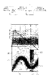
Fig. 2 illustrates a spectrogram of a mixture of a singing voice, castanets,
and applause
with zoomed in region additionally showing direction (orientation of arrows)
and anisotropy
measure (length of arrows) obtained by the structure tensor. The color of the
arrows
indicate whether the respective time-frequency bin is assigned to the harmonic
component (areas 210), to the percussive component (areas 230), or to the
residual
component (areas 220) based on the orientation and anisotropy information.
CA 03017558 2018-09-12
WO 2017/158102 PCT/EP2017/056257
9
All bins having neither a high nor a low local frequency change rate or a
certainty measure
that indicates a constant region were assigned to belong to the residual
component. An
example for this separation of a spectrogram can be seen in Fig. 2.
Embodiments perform
better for audio signals containing frequency modulated sounds than similar
methods
working on the magnitude spectrogram.
At first, a concept of structure tensor is described and this general concept
is extended to
be applicable in the context of audio processing.
In the following, matrices and vectors are written as bold letters for
notational
convenience. Furthermore, the (-) operator is used to index a specific
element. In this
case the matrix or vector is written as a non-bold letter to show its scalar
use.
At first, calculation of a spectrogram according to embodiments is described.
The audio
signal may, e.g., be a (discrete) input audio signal.
The structure tensor may be applied to the spectrogram representation of a
discrete input
audio signal X E Rm with a sampling frequency of/. For the spectral analysis
of x, the
short-time Fourier-transform (STFT)
N -1
X (b, k) E w(n)x(n + H b) exp (¨ i27r. N)
n=o (1)
is used, where X(b,k)E C, b denotes the frame index, k the frequency index and
W E R is a window function of length N (in other words: N is a length of an
analysis
window). HE N, H 5 N represents the analysis hop size of the window. It should
be noted
that since the STFT spectrum has a certain symmetry around the Nyquist point
at .111 , the
2
processing may, for example, be restricted to 0 5 k 5 -N, as the symmetry can
be
2
reconstructed during the inverse STFT.
By using the above formula (1), a spectrogram can be obtained. A spectrogram
comprises
a plurality of spectra, wherein the plurality of spectra succeed each other in
time. A
second spectrum of the plurality spectra succeeds a first spectrum in time, if
at least some
second time domain samples exist that are used to generate the second spectrum
and
CA 03017558 2018-09-12
WO 2017/158102 PCT/EP2017/056257
that are not used to generate the first spectrum, and that are time domain
samples that
refer to a later point-in-time than first time domain samples that are used to
generate the
first spectrum. Windows of time domain samples used for generating timely
neighbored
spectra may, for example, overlap.
5
In embodiments, the analysis window length N may, e.g., be defined to be:
256 samples N 5 2048 samples.
10 In some embodiments, the analysis window length may, e.g., be 2048. In
other
embodiments, the analysis window length may, e.g., be 1024 samples. In further
embodiments, the analysis window length may, e.g., be 768 samples. In still
further
embodiments, the analysis window length may, e.g., be 256 samples.
In embodiments, the analysis hop size H may, e.g., be in a range between 25 %
and 75 %
of the analysis window. In such embodiments:
0.25 N 5 H 0.75 N.
Thus, in such embodiments, if the analysis window has, e.g., 2048 samples (N =
2048),
the analysis hop size may, e.g., be in the range:
512 samples 5 H 5 1536 samples.
If the analysis window has, e.g., 256 samples (N = 256), the analysis hop size
may, e.g.,
be in the range:
64 samples 5 // 5 192 samples.
In preferred embodiments, the analysis hop size may, e.g., be 50 % of the
analysis
window. This corresponds to a window overlap of two subsequent analysis
windows of
50%.
In some embodiments, the analysis hop size may, e.g., be 25 % of the analysis
window.
This corresponds to a window overlap of two subsequent analysis windows of 75
%.
CA 03017558 2018-09-12
WO 2017/158102 PCT/EP2017/056257
11
In other embodiments, the analysis hop size may, e.g., be 75 % of the analysis
window.
This corresponds to a window overlap of two subsequent analysis windows of 25
%.
It should be noted that the concepts of the present invention are applicable
for any kind of
time domain to spectral domain transformation, such as for the MDCT (Modified
Discrete
Cosine Transform), MDST (Modified Discrete Sine Transform, DSTFT (Discrete
Short-
Time Fourier Transform), etc.
The real valued logarithmic spectrogram may, e.g., be calculated as:
S(b,k) = 20logio IX(b,
(2)
The magnitude spectrogram of the audio signal may be referred to as S and a
value of the
magnitude spectrogram for a time-frequency bin (I), k) may be referred to as
S(b, k).
In the following, calculation of the structure tensor according to embodiments
is described.
For the calculation of the structure tensor the partial derivatives of S are
needed. The
partial derivative with respect to time index b is given by
Sb S * d
(3)
while the partial derivative with respect to frequency index k is defined as
k = S * dT (4)
where d is a discrete differentiation operator (for example, for central
differences one
could choose d = [¨I, 0,11 / 2 ) and * denotes the 2-dimensional convolution.
Furthermore, it may be defined:
T11 ¨ (Sb Sb) * G (5)
T21 = T12 (Sk 0 Sb) * G (6)
CA 03017558 2018-09-12
WO 2017/158102 PCT/EP2017/056257
12
T22 = (Sk 0 Sk) * G (7)
where 0 is the point wise matrix multiplication, also known as the Hadamard
product and
G is a 2-D Gaussian smoothing filter having the standard deviation ab in time
index
direction and 0k in frequency index direction. The structure tensor T(b, k) is
then given
by a 2 x 2 symmetric and positive semidefinite matrix
T b k
Tii (b 1 k) 7112 (b, k)1
) . ( 1
[T21(b 1 k) 7'22(b, k)i
(8)
The structure tensor contains information about the dominant orientation of
the
spectrogram at position (b, k). It should be noted that in the special case
where G is a
scalar, T(b, k) does not contain more information than the gradient at this
position in the
spectrogram. However in contrast to the gradient, the structure tensor can be
smoothed
by G without cancellation effects, which makes it more robust against noise.
It should be noted, that a structure tensor T(b, k) is defined for each time-
frequency bin
(b, k) of the plurality of time-frequency bins. So when a plurality of time
frequency bins is
considered, e.g., the time-frequency bins (0, 0) (0,1) (0, 2) ...(1, 0) (1,1)
(1, 2) ... then there
exist a plurality of structure tensors T(0, 0) T(0,1) T(0, 2) ...T(1, 0), TO,
1) TO, 2) ... For
example, for each time-frequency bin (b, k)of the plurality of time-frequency
bins, one
structure tensor T(b, k) is determined.
In the following, calculation of angles and an anisotropy measure according to
embodiments is described.
The information about the orientation for each bin in the spectrogram is
obtained by
calculating the eigenvalues 2(b, k), p(b, k) with 42, k) p(b, k) and the
corresponding
eigenvectors v(b, k) = [v(b, k),v2(b, Or and w(b, k) = [w(b, k), w2(b, 101T of
the
structure tensor T(b, k). It should be noted that v(b, k), the eigenvector
corresponding to
the smaller eigenvalue 2(b, k), is pointing into the direction of lowest
change in the
spectrogram at index (b, k), while w(b, k) is pointing in to the direction of
highest change.
Thus, the angle of the orientation at a specific bin can be obtained by
( v2 (b. k)
(1(1), k) = atan -- -- E [-7r/2; ir/2]
V i (b, k) (9)
CA 03017558 2018-09-12
WO 2017/158102 PCT/EP2017/056257
13
v1(b, k) and v2 (b, k) are the components of the eigenvector v(b, k).
atan() indicates an inverse tangent function.
In addition, a measure of anisotropy
p(b,k)--A(b,k))2 ,
C (b, k) p,(b, k) + A(b, k) > e
0 , else
(10)
with eE R> can be determined for each bin. It should be noted that C(b,
[0; l].
Values of C(b, k) close to 1 indicate a high anisotropy of the spectrogram at
index (b, k),
while a constant neighborhood leads to values close to 0. The threshold e,
that defines a
limit on what should be considered anisotropic, can be chosen to further
increase the
robustness against noise.
The physical meaning of angle a(b, k) can be understood by considering a
continuous
signal with a change of instantaneous frequency A f during a time interval At
. Thus the
instantaneous frequency change rate R is denoted by
Af
At (11)
For example, according to embodiments, the angles (indicated by the direction
of the
arrows in Fig. 2) obtained by the structure tensor may, e.g., be translated
into a local
frequency change rate
R ______________________________ [HzIs]
At (11a)
for each time-frequency-bin of the spectrogram.
The change of the frequency for each time-frequency bin may, e.g., be referred
to as
instantaneous frequency change rate.
Considering sample rate, length and hop-size of the applied STFT analysis, a
relation
between the angles in the spectrogram and the instantaneous frequency change
rate
R(b, k) for each bin can be derived by
CA 03017558 2018-09-12
WO 2017/158102 PCT/EP2017/056257
14
fs2
R(b, k) = = tan(a(b, k))
H N (12)
Also the standard deviations of the smoothing filter G in the discrete domain
ab and crk
can be converted to the continuous physical parameters a, and af by
f
t = - ab, a f
(13)
In the following harmonic-percussive-residual separation using the structural
tensor is
described.
The information obtained via the structure tensor can be applied to the
problem of HPR
separation, e.g., to classify each bin in the spectrogram as being part of
either the
harmonic, the percussive or the residual component of the input signal.
Embodiments are based on the finding that bins assigned to the harmonic
components
should belong to rather horizontal structures, while bins belonging to rather
vertical
structures should be assigned to the percussive component. Furthermore, bins
that do not
belong to any kind of oriented structure should be assigned to the residual
component.
According to embodiments, a bin (b, k) may, e.g., be assigned to the harmonic
component, if it satisfies the first of the following two constraints.
According to preferred embodiments, a bin (b, k) may, e.g., be assigned to the
harmonic
.. component, if it satisfies both of the following two constraints:
The first constraint may, e.g., be that the absolute value of the angle a(b,
k) is
smaller than (or equal to) a threshold ah. The threshold ah may, e.g., be in
the
range ah c [0; r/2]. This means, that the bin should be part of some spectral
structure that does not have a slope bigger or smaller than ah. This way also
frequency modulated sounds can be considered to be part of the harmonic
component, depending on the parameter ah.
The second constraint may, e.g., be that the measure of anisotropy C(b, k)
supports that the bin (b, k) is part of some directed, anisotropic structure,
and
therefore exceeds a second threshold c. It should be noted that for a given
bin
CA 03017558 2018-09-12
WO 2017/158102 PCT/EP2017/056257
(b, lc), the angle a(b, k) and the measure of anisotropy C(b, k) together
define a
point in R2 given in polar coordinates.
Similarly, in embodiments, another angle threshold a,, is assigned to define
when a bin
5 should be assigned to the percussive component (areas 330 with vertical
lines in Fig. 3).
Thus, according to embodiments, a bin (b, k) may, e.g., be assigned to the
percussive
component, if it satisfies the first of the following two constraints.
10 According to preferred embodiments, a bin (b, k) may, e.g., be assigned
to the percussive
component, if it satisfies both of the following two constraints:
The first constraint may, e.g., be that the absolute value of the angle a(b,
k) is
greater than (or equal to) a threshold a p . The threshold ap may, e.g., be in
the
15 range a,., E [0; r/2]. This means, that the bin should be part of some
spectral
structure that does not have a slope bigger or smaller than a p . This way
also
frequency modulated sounds can be considered to be part of the harmonic
component, depending on the parameter a p .
- The second constraint may, e.g., be that the measure of anisotropy C(b,
1c)
supports that the bin (b, k) is part of some directed, anisotropic structure,
and
therefore exceeds a second threshold C. It should be noted that for a given
bin
k), the angle a(b , k) and the measure of anisotropy C(b, k) together define a
point in lie given in polar coordinates.
Finally, in embodiments, all bins that are assigned to neither the harmonic
nor the
percussive component may, e.g., be assigned to the residual component.
The above-described assignment process can be expressed by defining a mask for
the
harmonic component Mh, a mask for the percussive component Mp and a mask for
the
residual component Mr.
It should be noted, that instead of using the threshold a1 and the threshold
a,,
thresholds may in embodiments, e.g., be defined on the maximum absolute
frequency
change rate riõ 5) E R>C) with rp rh to give the choice of parameters a better
physical
interpretation. The masks are then given by:
CA 03017558 2018-09-12
WO 2017/158102 PCT/EP2017/056257
16
Mh(b, k) 411 , IR(b, k)I <rh A C (b, k) > c
0 ,else
(14)
M (b k) {1 , 117(b, k)I > rp A C(b, k) > c
,
0 , else
(15)
Mr(b, k) = 1 ¨ Mh(b, k) Mp(b, k) (16)
Finally, the STFT of the harmonic component Xh, the percussive component Xr
and the
residual component X. are obtained by
Xh = Mh 0 X (17)
X = M X
(18)
Xr = Mr 0 X (19)
The corresponding time signals can then be calculated via the inverse STFT.
Fig. 3 illustrates a range of orientation/anisotropy values computed by the
structure
tensor.
In particular, Fig. 3 depicts the subset of all points that lead to an
assignment to the
harmonic component. In particular, values in the areas 310 with wavy lines
lead to an
assignment to the harmonic component.
Values in the areas 330 with vertical lines lead to an assignment to the
percussive
component.
Values in the areas 320 that are dotted lead to an assignment to the residual
component.
The threshold ah defines line 301 in Fig. 3, and the threshold a defines line
302 in Fig.
3.
CA 03017558 2018-09-12
WO 2017/158102 PCT/EP2017/056257
17
Fig. 5 illustrates an apparatus according to an embodiment, wherein the
apparatus
comprises a signal generator 130 being configured to generate an audio output
signal
depending on the assigning of the plurality of time-frequency bins to the two
or more
signal component groups.
For example, signal generator may filter the different components of the audio
signal by
applying different weighting factors on the magnitude values of the time-
frequency bins of
the different signal component groups. For example, the harmonic signal
component
group may have a first weighting factor wh, the percussive signal component
group may
have a second weighting factor wp, and the residual signal component group may
have a
first weighting factor wr, and the magnitude value of each time-frequency bin
of the
plurality of time-frequency bins may, e.g., be weighted with the weighting
factor of the
signal component group, the time-frequency bin is assigned to.
For example, to emphasize harmonic signal components, in an embodiment, where
the
weighting factors are multiplied the with linear magnitude values e.g.,
wh = 1.3, wp = 0.7, and w,. = 0.2
For example, to emphasize harmonic signal components, in an embodiment, where
the
weighting factors are added to the logarithmic magnitude values e.g.,
wh = +0.26, wp = ¨0.35, and w, = ¨1.61
For example, to emphasize percussive signal components, in an embodiment,
where the
weighting factors are multiplied the with linear magnitude values e.g.,
wh = 0.7, wp = 1.3, and w,. = 0.2
For example, to emphasize percussive signal components, in an embodiment,
where the
weighting factors are added to the logarithmic magnitude values e.g.,
wh = ¨0.35, wp = +0.26, and W, = ¨1.61
Thus, the signal generator 130 is configured to apply a weighting factor on
the magnitude
value of each time-frequency bin of the plurality of time-frequency bins to
obtain the audio
CA 03017558 2018-09-12
WO 2017/158102 PCT/EP2017/056257
18
output signal, wherein the weighting factor that is applied on said time-
frequency bin
depends on the signal component group to which said time-frequency bin is
assigned.
In a particular embodiment of Fig. 5, the signal processor 130 may, e.g., be
an upmixer
being configured to upmix the audio signal to obtain the audio output signal
comprising
two or more audio output channels. The upmixer may, e.g., be configured to
generate the
two or more audio output channels depending on the assigning of the plurality
of time-
frequency bins to the two or more signal component groups.
For example, the two or more audio output channels may be generated from the
audio
signal filter the different components of the audio signal by applying
different weighting
factors on the magnitude values time-frequency bins of the different signal
component
groups as described above.
However, to generate the different audio channels different weights for the
signal
component groups may be used that may, e.g., be specific for each of the
different audio
output channels.
For example, for a first audio output channel, the weights to be added to the
logarithmic
magnitude values may, e.g., be
win = +0.26, w1õ = ¨0.35, and wir = ¨1.61.
And for a second audio output channel, the weights to be added to the
logarithmic
magnitude values may, e.g., be
W2h = +0.35, w212 = ¨0.26, and w2,. = ¨1.61.
For example, when upmixing the audio signal to obtain five audio output
channels front
left, center, right, left surround and right surround:
The harmonic weighting factor wit, may be greater for generating the left,
center
and right audio output channels compared to the harmonic weighting factor w2h
for
generating the left surround and right surround audio output channels.
The percussive weighting factor w1p may be smaller for generating the left,
center
and right audio output channels compared to the percussive weighting factor
w2p
for generating the left surround and right surround audio output channels.
CA 03017558 2018-09-12
WO 2017/158102 PCT/EP2017/056257
19
Individual weighting factors may be used for each audio output channel to be
generated.
Fig. 6 illustrates an apparatus according to an embodiment, wherein the
apparatus
.. comprises one or more microphones 171, 172 for recording the audio signal.
In Fig. 6, the first microphone 171 records a first audio channel of the audio
signal. The
optional second microphone 172 records an optional second audio channel of the
audio
signal.
Moreover, the apparatus of Fig. 6 further comprises a magnitude spectrogram
generator
180 for generating the magnitude spectrogram of the audio signal from the
audio signal
which comprises the first audio channel and optionally comprises the optional
second
audio channel. Generating a magnitude spectrogram from an audio signal is a
well-known
concept for a person skilled in the art.
In the following, evaluation of embodiments is considered.
To show the effectiveness of embodiments in capturing frequency modulated
sounds in
the harmonic component, the HPR method based on the structure tensor (HPR-ST)
according to embodiments is compared with the non-iterative method based on
median
filtering presented in [10] (HPR-M). Additionally, the metrics are also
computed for the
separation results with ideal binary masks (IBM) that served as a reference
for the
maximal achievable separation quality.
Considering a system-under-test parameters, for both HPR-ST as well as HPR-M,
the
STFT parameters were chosen to be fs = 22050Hz, N = 1024 and H = 256, using a
sine
window for w. The separation parameters for HPR-M were chosen as in the
experiments
performed in [10]. According to embodiments, the structure tensor is
calculated using a
.. differential operator, for example, the Scharr-Operator [17] as discrete
differentiation
operator d. The smoothing was performed using a 9 x 9 isotropic Gaussian
filter with the
standard deviations ab ak =1.4 which leads to cr, 16ms and o-f 30Hz . Finally,
the thresholds for the separation were set to e = 20, c = 0.2 and rh = r
=10000Hzis .
It should be noted that by the choice of rh and ç according to embodiments,
even very
steep structures in the spectrogram are assigned to the harmonic component.
Embodiments employ the observations about real world vibrato sounds as for
example
shown in Fig. 2. Here, you can see that at some instances the vibrato in the
singing voice
CA 03017558 2018-09-12
WO 2017/158102 PCT/EP2017/056257
has a very high instantaneous frequency change rate. Furthermore, it should be
noted
that by choosing rh = rp , an assignment of a bin in the spectrogram to the
residual
component is purely dependent on its anisotropy measure.
5 The effectiveness of HPR-ST according to embodiments was evaluated by
comparing it to
the state-of-art median filtering based method HPR-M presented in [10] by
means of both
objective evaluation measures as well as audio examples.
To compare the behavior of HPR-ST according to embodiments and HPR-M of the
prior
10 art when applied to signals containing frequency modulated sounds to
obtain objective
results, two test items were generated.
Test item 1 consists of the superposition of purely synthetic sounds. The
harmonic source
was chosen to be a vibrato tone with a fundamental frequency of 1000Hz, a
vibrato
15 frequency of 3Hz, vibrato extent of 50Hz and 4 overtones. For the
percussive source
several impulses are used, while white noise represents the neither harmonic
nor
percussive residual source.
Test item 2 was generated by superimposing real world signals of singing voice
with
20 vibrato (harmonic), castanets (percussive), and applause (neither harmonic
nor
percussive).
Interpreting the HPR separation of these items as a source separation problem,
standard
source separation evaluation metrics have been computed (source to distortion
ratio SDR,
source to interference ratio SIR, and source to artifacts ratios SAR, as
introduced in [18])
for the separation results of both procedures. The results are shown in table
1.
Table 1 depicts objective evaluation measures, where all values are given in
dB:
CA 03017558 2018-09-12
WO 2017/158102 PCT/EP2017/056257
21
SUR SIR SAR
ri)*
Cl, E-4
CO
04 c4
c21.
_ _____________________________ . __
= Vibrato 29.43 1 1 .51 21.25 34.26 27.94 30.01 31.16 11.61 21.88
E Impulses 8.56 -10.33 -1.47 20.31 -7.96 12.03 8.90 2.02 -1.00
2, Noise 8.49 -13.53 2.58
24.70 -11.99 14.12 8.61 3.97 3.06
eq Vocals 14.82 6.48 9.18 22.75
20.83 15.61 15.60 6.68 10.42
Castanets 8.48 3.79 2.37 21.59 16.09 17.96 8.73 4.16 2.56
Applause 7.39 -2.03 -0.37 20.31 1.11 6.34 7.66 3.33 1.58
_ . _
(Table 1)
For item 1 HPR-ST yields a SDR of 21.25dB for the vibrato tone, and is
therefore closer to
the optimal separation result of IBM (29.43dB) than to the separation result
of HPR-M
(11.51dB). This indicates that HPR-ST improves on capturing this frequency
modulated
sound in the harmonic component in comparison to HPRM. This is also shown in
Fig. 4.
Fig. 4 illustrates a comparison between the HPR-M and HPR-ST method for an
excerpt of
the synthetic input signal (item 1). For enhanced visibility the spectrograms
were
calculated with different STFT parameters than used for the separation
algorithms.
Fig. 4 (a) illustrates the frequency of the input signal with respect to time.
In Fig. 4, the
spectrograms of the harmonic components and the sum of the percussive and
residual
component computed for both procedures are plotted. It can be seen that for
HPR-M the
steep slopes of the vibrato tone leaked into the residual component (Fig. 4
(b) and (c) ),
while HPR-ST (Fig. 4 (d) and (e) ) yields a good separation. This also
explains the very
low SIR values of HPRM for the residual component compared to HPR-ST (-11.99dB
vs.
14.12dB).
It should be noted that the high SIR value of HPR-M for the harmonic component
only
reflects that there are little interfering sounds from the other components,
not that the
sound of the vibrato is well captured as a whole. In general most of the
observations for
item 1 are less pronounced, but also valid for the mixture of real world
sounds in item 2.
For this item, the SIR value of HPR-M for the vocals even exceeds the SIR
value of HPR-
ST (20.83dB vs. 15.61dB). Again, the low SIR value for the applause supports
that
portions of the vibrato in the vocals leaked into the residual component for
HPR-M
(1.11dB) while the residual component of HPR-ST contains less interfering
sounds
CA 03017558 2018-09-12
WO 2017/158102 PCT/EP2017/056257
22
(6.34dB). This indicates that embodiments were capable of capturing the
frequency
modulated structures of the vocals much better than HPR-M.
Summarizing the results, for signals that contain frequency modulated tones,
the HPR-ST
concept of embodiments provides much better separation results compared to HPR-
M.
Some embodiments employ the structure tensor for singing voice detection.
(Singing
voice detection according to the prior art is described in [2]).
Although some aspects have been described in the context of an apparatus, it
is clear that
these aspects also represent a description of the corresponding method, where
a block or
device corresponds to a method step or a feature of a method step.
Analogously, aspects
described in the context of a method step also represent a description of a
corresponding
block or item or feature of a corresponding apparatus. Some or all of the
method steps
may be executed by (or using) a hardware apparatus, like for example, a
microprocessor,
a programmable computer or an electronic circuit. In some embodiments, one or
more of
the most important method steps may be executed by such an apparatus.
Depending on certain implementation requirements, embodiments of the invention
can be
implemented in hardware or in software or at least partially in hardware or at
least partially
in software. The implementation can be performed using a digital storage
medium, for
example a floppy disk, a DVD, a Blu-Ray, a CD, a ROM, a PROM, an EPROM, an
EEPROM or a FLASH memory, having electronically readable control signals
stored
thereon, which cooperate (or are capable of cooperating) with a programmable
computer
.. system such that the respective method is performed. Therefore, the digital
storage
medium may be computer readable.
Some embodiments according to the invention comprise a data carrier having
electronically readable control signals, which are capable of cooperating with
a
.. programmable computer system, such that one of the methods described herein
is
performed.
Generally, embodiments of the present invention can be implemented as a
computer
program product with a program code, the program code being operative for
performing
.. one of the methods when the computer program product runs on a computer.
The
program code may for example be stored on a machine readable carrier.
CA 03017558 2018-09-12
WO 2017/158102 PCT/EP2017/056257
23
Other embodiments comprise the computer program for performing one of the
methods
described herein, stored on a machine readable carrier.
In other words, an embodiment of the inventive method is, therefore, a
computer program
having a program code for performing one of the methods described herein, when
the
computer program runs on a computer.
A further embodiment of the inventive methods is, therefore, a data carrier
(or a digital
storage medium, or a computer-readable medium) comprising, recorded thereon,
the
computer program for performing one of the methods described herein. The data
carrier,
the digital storage medium or the recorded medium are typically tangible
and/or
non-transitory.
A further embodiment of the inventive method is, therefore, a data stream or a
sequence
of signals representing the computer program for performing one of the methods
described herein. The data stream or the sequence of signals may for example
be
configured to be transferred via a data communication connection, for example
via the
Internet.
A further embodiment comprises a processing means, for example a computer, or
a
programmable logic device, configured to or adapted to perform one of the
methods
described herein.
A further embodiment comprises a computer having installed thereon the
computer
program for performing one of the methods described herein.
A further embodiment according to the invention comprises an apparatus or a
system
configured to transfer (for example, electronically or optically) a computer
program for
performing one of the methods described herein to a receiver. The receiver
may, for
example, be a computer, a mobile device, a memory device or the like. The
apparatus or
system may, for example, comprise a file server for transferring the computer
program to
the receiver.
In some embodiments, a programmable logic device (for example a field
programmable
gate array) may be used to perform some or all of the functionalities of the
methods
described herein. In some embodiments, a field programmable gate array may
cooperate
with a microprocessor in order to perform one of the methods described herein.
Generally,
the methods are preferably performed by any hardware apparatus.
CA 03017558 2018-09-12
WO 2017/158102 PCT/EP2017/056257
24
The apparatus described herein may be implemented using a hardware apparatus,
or
using a computer, or using a combination of a hardware apparatus and a
computer.
The methods described herein may be performed using a hardware apparatus, or
using a
computer, or using a combination of a hardware apparatus and a computer.
The above described embodiments are merely illustrative for the principles of
the present
invention. It is understood that modifications and variations of the
arrangements and the
details described herein will be apparent to others skilled in the art. It is
the intent,
therefore, to be limited only by the scope of the impending patent claims and
not by the
specific details presented by way of description and explanation of the
embodiments
herein.
CA 03017558 2018-09-12
WO 2017/158102
PCT/EP2017/056257
References:
[1] Aggelos Gkiokas, Vassilios Katsouros, George Carayannis, and Themos
Stafylakis, "Music tempo estimation and beat tracking by applying source
5 separation and metrical relations", in Proceedings of the IEEE
International
Conference on Acoustics, Speech, and Signal Processing (ICASSP), 2012, pp.
421-424.
[2] Bernhard Lehner, Gerhard Widmer, and Reinhard Sonnleitner, "On the
reduction
10 of false positives in singing voice detection", in Proceedings of the
IEEE
International Conference on Acoustics, Speech, and Signal Processing (ICASSP),
Florence, Italy, 2014, pp. 7480-7484.
[3] Yushi Ueda, Yuuki Uchiyama, Takuya Nishimoto, Nobutaka Ono, and Shigeki
15 Sagayama, "HMM-based approach for automatic chord detection using
refined
acoustic features", in Proceedings of the IEEE International Conference on
Acoustics, Speech, and Signal Processing (ICASSP), Dallas, Texas, USA, 2010,
pp. 5518-5521.
20 [4] Nobutaka Ono, Kenichi Miyamoto, Hirokazu Kameoka, and Shigeki
Sagayama, "A
real-time equalizer of harmonic and percussive components in music signals",
in
Proceedings of the International Society for Music Information Retrieval
Conference (ISMIR), Philadelphia, Pennsylvania, USA, 2008, pp. 139-144.
25 [5] Nobutaka Ono, Kenichi Miyamoto, Jonathan LeRoux, Hirokazu
Kameoka, and
Shigeki Sagayama, "Separation of a monaural audio signal into
harmonic/percussive components by complementary diffusion on spectrogram", in
European Signal Processing Conference, Lausanne, Switzerland, 2008, pp. 240-
244.
[6] Derry Fitzgerald, "Harmonic/percussive separation using median
filtering", in
Proceedings of the International Conference on Digital Audio Effects (DAFX),
Graz, Austria, 2010, pp. 246-253.
[7] Scott N. Levine and Julius 0. Smith III, "A sines+transients+noise
audio
representation for data compression and time/pitch scale modications", in
Proceedings of the AES Convention, 1998.
CA 03017558 2018-09-12
WO 2017/158102 PCT/EP2017/056257
26
[8] Tony S. Verma and Teresa H.Y. Meng, "An analysis/synthesis tool for
transient
signals that allows a flexible sines+transients+noise model for audio", in
Proceedings of the IEEE International Conference on Acoustics, Speech, and
Signal Processing (ICASSP), Seattle, Washington, USA, May 1998, pp. 3573-
3576.
[9] Laurent Daudet, "Sparse and structured decompositions of signals with
the
molecular matching pursuit', IEEE Transactions on Audio, Speech, and Language
Processing, vol. 14, no. 5, pp. 1808-1816, September 2006.
[10] Jonathan Driedger, Meinard Muller, and Sascha Disch, "Extending
harmonic-
percussive separation of audio signals", in Proceedings of the International
Conference on Music Information Retrieval (ISMIR), Taipei, Taiwan, 2014, pp.
611-616.
[11] Jeongsoo Park and Kyogu Lee, "Harmonic-percussive source separation using
harmonicity and sparsity constraints", in Proceedings of the International
Conference on Music Information Retrieval (1SMIR), Malaga, Spain, 2015, pp.
148-154.
[12] Josef Bigun and Gosta H. Granlund, "Optimal orientation detection of
linear
symmetry', in Proceedings of the IEEE First International Conference on
Computer
Vision, London, UK, 1987, pp. 433-438.
[13] Hans Knutsson, "Representing local structure using tensors", in 6th
Scandinavian
Conference on Image Analysis, Oulu, Finland, 1989, pp. 244-251.
[14] Chris Harris and Mike Stephens, "A combined corner and edge detector",
in
Proceedings of the 4th Alvey Vision Conference, Manchester, UK, 1988, pp. 147-
151.
[15] Rolf Bardeli, "Similarity search in animal sound databases", IEEE
Transactions on
Multimedia, vol. 11, no. 1, pp. 68-76, January 2009.
[16] Matthias Zeppelzauer, Angela S. Stager, and Christian Breiteneder,
"Acoustic
detection of elephant presence in noisy environments", in Proceedings of the
2nd
ACM International Workshop on Multimedia Analysis for Ecological Data,
Barcelona, Spain, 2013, pp4.3-8.
CA 03017558 2018-09-12
WO 2017/158102 PCT/EP2017/056257
27
[17] Hanno Scharr, "Optimale Operatoren in der digitalen Bildverarbeitung",
Dissertation, IWR, Fakultat fur Physik und Astronomie, Universitat Heidelberg,
Heidelberg, Germany, 2000.
[18] Emmanuel Vincent, Rerni Gribonval, and Cedric Fevotte, "Performance
measurement in blind audio source separation", IEEE Transactions on Audio,
Speech, and Language Processing, vol. 14, no. 4, pp. 1462-1469, 2006.