Note: Descriptions are shown in the official language in which they were submitted.
84600472
METHODS. APPARATUSES. AND SYSTEMS FOR COOLING
This application claims the benefit of U.S. Patent Application No. 62/309,886,
filed March 17,2016.
BRIEF DESCRIPTION OF THE DRAWINGS
FIG. 1 is a schematic of a coding system, according to an exemplary embodiment
of
the present disclosure;
FIG-. 2 is a schematic of a cooling system, according to an exemplary
embodiment of
the present disclosure.
FIG. 3A is a front isometric view of a cooling system, according to an
exemplary
embodiment of the present disclosure;
FIG. 3B is a rear isometric view of the cooling system shown in Figure 3A;
FIG. 4 is a top internal view of a cooling system, according to an exemplary
embodiment of the present disclosure;
FIG. 5 is a side cross-sectional view of an interior of a cooling system,
according to
an exemplary embodiment of the present disclosure;
FIG. 6 is an illustration of an internal-external cooling mechanism of a
cooling
system, according to an exemplary embodiment of the present disclosure;
FIG. 7 is a front isometric view of a cooling system, according to an
exemplary
embodiment of the present disclosure;
FIG. 8 is a top internal view of the cooling system shown in Figure 7;
FIG. 9 is a side cross-sectional view of the cooling system shown in Figure 7;
FIG. 10 is a rear cross-sectional view of an interior of the cooling system
shown in
Figure 9;
FIG-. 11 is an isometric view of a cooling station of a cooling system,
according to an
exemplary embodiment of the present disclosure;
1
CA 3018084 2020-03-05
CA 03018084 2018-09-17
WO 2017/161324
PCT/US2017/023052
FIG. 12 is a front view of the cooling station shown in Figure 11 illustrating
an
internal cooling mechanism of the cooling system;
FIG. 13 is a flowchart of a cooling system, according to an exemplary
embodiment of
the present disclosure;
FIG. 13A is a flowchart of a sensor feedback system, according to an exemplary
embodiment of the present disclosure.
FIG. 14 is a view of an output end the cooling system of the present
disclosure
FIG. 15 is a view of an input end of the cooling system of the present
disclosure.
FIG. 16 is an internal view featuring aspects of a conveyor system of the
present
disclosure.
FIG. 17 is an internal view featuring aspects of a conveyor system of the
present
di scl osure.FIG. 18A-E is a flowchart of an independent remote packer model
system
for collecting, displaying and using produce data from harvest-to-sale.
FIG. 19A-E is a flowchart of a farm-based pack house model system for
collecting,
displaying and using produce data from harvest-to-sale.
DESCRIPTION OF EMBODIMENTS
Produce begins to ripen and/or spoil as soon as it is harvested. Cooling the
produce immediately and rapidly after harvesting slows this ripening and/or
spoilage.
Existing cooling systems for produce are slower than desired and have led to
decreased overall shelf life of the produce.
In some cooling systems, workers in the field may pack the produce in
produce containers, such as cartons, trays or boxes, that are then stacked on
pallets
and transferred via a flatbed truck or other transportation to a distribution
point. At
this distribution point, the cartons may be placed in a large refrigerated
building to
2
CA 03018084 2018-09-17
WO 2017/161324
PCT/US2017/023052
cool the produce as quickly as possible. Other systems for cooling produce are
disclosed in U.S. Patent Nos. 5,992,169, 5,375,431, and 5,386,703. These
systems
disclose apparatuses and methods for cooling produce via the use of vacuum
chambers /pumps and hydro cooling.
Methods, apparatuses, and systems are provided for cooling produce via a
cooling system. Embodiments include a cooling system having: a mobile
container/trailer with separated sections to continuously cool produce to, and
maintain
the produce at, an optimal temperature; a conveyor system to convey produce
across
the sections of the mobile container; and a sensor feedback system to
continuously
measure, track, and receive relevant feedback/data regarding the produce. The
sensor
feedback system may be a dynamic real-time feedback system allowing a user to
ensure that the produce is being cooled to an optimal temperature prior to
being
processed.
In exemplary embodiments, relevant data (e.g., weight, temperature) regarding
the produce may be continuously measured, tracked, displayed to a user, and/or
stored
in a database (locally and/or in the cloud). Importantly, this data may be
obtained,
tracked, and stored from as early as the point of harvest of the produce, at
various
points during cooling of the produce via the cooling system, and all the way
up the
supply chain to a distribution center, grocery store, and eventually, the
customer.
Embodiments of the cooling system may include cooling mechanisms
integrated within and/or attached to a mobile container/trailer that may be
easily
moved to different locations. As such, the cooling system may be mobile and
brought
directly to fresh produce during or right after harvesting. The result is
optimized on-
site cooling leading to longer shelf life for produce. The system also results
in reduced
3
CA 03018084 2018-09-17
WO 2017/161324
PCT/US2017/023052
costs associated with handling and decreased time to market ¨ all leading to
fresher
produce and substantial cost savings.
The inventions disclosed herein include a system for cooling produce. One
embodiment of a system for cooling produce comprises a mobile container having
a
plurality of cooling stations therein. The mobile container has an input
opening on a
first end and an output opening on an opposing end thereof. The input and
output
openings are configured to receive produce containers therethrough. The mobile
container has a staging section adjacent the input opening for receiving
produce
containers conveyed through the input opening. The staging section provides a
cooled
environment for initial cooling of produce. A rapid cooling section has first,
second,
and third cooling stations. The first cooling station is positioned to receive
produce
containers conveyed from the staging section, and has an associated cooling
mechanism for cooling produce in the first cooling station. The second cooling
station
is positioned to receive produce containers conveyed from the first cooling
station,
and has an associated cooling mechanism for cooling produce in the second
cooling
station. The third cooling station is positioned to receive produce containers
conveyed
from the second cooling station, and has an associated cooling mechanism for
cooling
produce in the third cooling station. The first, second and third cooling
stations
together sequentially cooling produce to an optimal temperature by at least
the third
cooling station. A discharge section is positioned to receive produce
containers
conveyed from the third cooling station of the rapid cooling section and
maintain
produce at the optimal temperature. The discharge station is configured to
convey
produce containers out of the mobile container through the output opening.
The system can be provided with a conveyor system in the mobile container
for conveying produce containers from the input end to the output end to
thereby
4
CA 03018084 2018-09-17
WO 2017/161324
PCT/US2017/023052
sequentially transport produce containers through the staging, rapid cooling
and
discharge sections. A plurality of doors can be provided, the doors positioned
to
selectively close and thereby retain cold air for circulation within each of
the first
cooling station, the second cooling station, and the third cooling station
during
cooling of produce. Each of the plurality of doors can be an automatic roll-up
door.
In some embodiments, the cooling mechanism in the first, second, and third
cooling stations includes chilled air outputted via cooling fans and coils
located on a
first side of each of the first, second, and third cooling stations to thereby
force chilled
air over produce. Air is internally recirculated via return air ducts and fans
located on
an opposing second side of each of the first, second, and third cooling
stations back to
the cooling fans and coils located on the first side.
A sensor feedback system can be provided that is configured to continuously
measure and track temperature of produce as produce containers are conveyed
through the system. The sensor feedback system can be a dynamic real-time
sensor
feedback system. The sensor feedback system can be configured to measure and
track
the weight of produce as produce containers are conveyed through the system.
In
some embodiments, the sensor feedback system includes at least a first sensor
integrated with the conveyor system, which is used to measure weight of at
least one
pallet upon entering the system, and a second sensor placed within the at
least one
pallet, which is used to measure the temperature of produce within the at
least one
pallet. The first and second sensors send at least one of weight and
temperature
information to a PLC device. The PLC device obtains at least the weight and
temperature information of the produce and sends the weight and temperature
information to at least one of a local storage and a cloud-based database. The
sensor
feedback system can include sensors mounted within the container that allow a
user to
5
CA 03018084 2018-09-17
WO 2017/161324
PCT/US2017/023052
determine the location of the at least one pallet in the cooling system. The
PLC device
can be connected to and control at least one of the cooling mechanism,
conveyor
system, and sensor feedback system.
Methods of cooling produce are also provided. One method of cooling
produce comprise inserting at least one pallet containing produce into a
cooling
system. The cooling system includes a mobile container including at least a
separated
first, second, and third section. The first section holds the at least one
pallet
containing produce in a semi-cooled environment. The second section includes a
cooling mechanism to cool the produce within the at least one pallet to an
optimal
temperature. The third section includes the cooling mechanism to maintain
cooled
produce in the at least one pallet at the optimal temperature. A conveyor
system is
provided, the convey system including at least one conveyor longitudinally
extending
along the length of the mobile container. The conveyor system is used to
convey the
at least one pallet from the first section to each of the second and third
sections. A
sensor feedback system is configured to continuously measure and track at
least the
weight of the at least one pallet and temperature of the produce within the at
least one
pallet as the at least one pallet is conveyed across the cooling system. The
method
includes transporting the produce from the first section to the second section
via the
conveyor system; cooling the produce within the at least one pallet to the
optimal
temperature via the cooling mechanism; continuously measuring and tracking at
least
the weight and temperature of the produce within the at least one pallet via
the sensor
feedback system while conveying the at least one pallet along the second
section to
ensure the produce remains at the optimal temperature; transporting the
produce from
the second section to the third section via the conveyor system; and
maintaining the
produce within the at least one pallet at the optimal temperature.
6
CA 03018084 2018-09-17
WO 2017/161324
PCT/US2017/023052
In some embodiments, the second section includes a first cooling station, a
second cooling station, and a third cooling station, each of which is
configured to hold
at the least one pallet being conveyed across the system. The cooling
mechanism in
the first, second, and third cooling stations can include chilled air
outputted via vents
located on a first side of the container to cool produce in the at least one
pallet, with
heat from the produce being exhausted out via vents located on an opposing
second
side of the container. In some embodiments, the cooling mechanism in the
first,
second, and third cooling stations includes chilled air outputted via cooling
fans and
coils located on a first side of each of the first, second, and third cooling
stations to
cool produce in the at least one pallet, with heat from the produce being
internally
recirculated via return air ducts and fans located on an opposing second side
of each
of the first, second, and third cooling stations back to the cooling fans and
coils
located on the first side.
In some embodiments, the sensor feedback system includes at least a first
sensor integrated with the conveyor system, which is used to measure weight of
the at
least one pallet upon entering the system, and a second sensor placed within
the at
least one pallet, which is used to measure the temperature of the produce
within the at
least one pallet. The sensor feedback system can include sensors mounted
within the
container that allow a user to determine the location of the at least one
pallet in the
cooling system.
In some embodiments, the system comprises a mobile container including a
cooling mechanism, the mobile container having separated sections to
continuously
cool produce to, and maintain the produce at, an optimal temperature via the
cooling
mechanism; a conveyor system to convey produce across the separated sections
of the
container, and a sensor feedback system to continuously measure, track, and
store
7
CA 03018084 2018-09-17
WO 2017/161324
PCT/US2017/023052
relevant information regarding the produce being conveyed across the
container, and
to control the movement of the conveyor system based on this information The
cooling mechanism can include an external cooling mechanism that interacts
with an
internal cooling mechanism installed within the container to cool the produce.
The
cooling mechanism can be an entirely internal cooling mechanism installed
within the
container.
In some embodiments, the system for cooling produce comprises a mobile
container having an input opening on a first end and an output opening on an
opposing end thereof The input and output openings are configured to receive
produce containers therethrough. The mobile container has a staging section
adjacent
the input opening for receiving produce containers conveyed through the input
opening. The staging section provides a cooled environment for initial cooling
of
produce. The system includes a rapid cooling section configured for cooling
produce
to an optimal temperature. A discharge section is positioned to receive
produce
containers conveyed from the rapid cooling section and maintain produce at the
optimal temperature. The discharge station is configured to convey produce
containers out of the mobile container through the output opening. The rapid
cooling
section can comprise: a first cooling station positioned to receive produce
containers
conveyed from the staging section, the first cooling station having an
associated
cooling mechanism for cooling produce in the first cooling station; a second
cooling
station positioned to receive produce containers conveyed from the first
cooling
station, the second cooling station having an associated cooling mechanism for
cooling produce in the second cooling station; and a third cooling station
positioned to
receive produce containers conveyed from the second cooling station, the third
cooling station having an associated cooling mechanism for cooling produce in
the
8
CA 03018084 2018-09-17
WO 2017/161324
PCT/US2017/023052
third cooling station. The first, second and third cooling stations together
sequentially
cool produce to the optimal temperature by at least the third cooling station.
In some embodiments a conveyor system is provided in the mobile container
for conveying produce containers from the input end to the output end to
thereby
sequentially transport produce containers through the staging, rapid cooling
and
discharge sections. In some embodiments, the conveyor system includes at least
seven
conveyors extending along each of the first section, second section, and third
section
of the container. A plurality of doors can be provided, the the doors
positioned to
selectively close and thereby retain cold air for circulation within each of
the first
cooling station, the second cooling station, and the third cooling station
during
cooling of produce. The doors can be automatic roll-up doors. In some
embodiments,
the mobile container is fixed on a wheeled trailer chassis for use in moving
the mobile
container.
In some embodiments, the cooling mechanism in the first, second, and third
cooling stations includes chilled air outputted via vents located on a first
side of the
container to flow chilled air over produce and then into exhaust vents located
on an
opposing second side of the container. In some embodiments, the cooling
mechanism
in the first, second, and third cooling stations includes chilled air
outputted via
cooling fans and coils located on a first side of each of the first, second,
and third
cooling stations to thereby force chilled air over produce, with air being
internally
recirculated via return air ducts and fans located on an opposing second side
of each
of the first, second, and third cooling stations back to the cooling fans and
coils
located on the first side. The cooling mechanism in the third section can
include
chilled air outputted via vents located on opposing sides of the container to
thereby
force chilled air over produce from opposing sides.
9
84600472
According to some embodiments of the present invention, there is provided a
system,
comprising: a mobile container having an input opening on a first end and an
output opening
on an opposing end thereof, the input opening and the output opening
configured to receive
produce containers therethrough, the mobile container having a staging section
adjacent the
input opening that receives produce containers conveyed through the input
opening, the staging
section provides a cooled environment for initial cooling of a produce, a
rapid cooling section
having a first cooling station positioned to receive the produce containers
conveyed from the
staging section, the first cooling station having an associated first cooling
mechanism that cools
the produce in the first cooling station, the first cooling mechanism includes
a first vent
configured to transport chilled air to the produce in the first cooling
station, wherein the first
vent is located on a first side of the first cooling station, a second cooling
station positioned to
receive the produce containers conveyed from the first cooling station, the
second cooling
station having an associated second cooling mechanism that cools the produce
in the second
cooling station, the second cooling mechanism includes a second vent
configured to transport
chilled air to the produce in the second cooling station, wherein the second
vent is located on a
first side of the second cooling station, the first side of the first cooling
station opposite the first
side of the second cooling station, and a third cooling station positioned to
receive the produce
containers conveyed from the second cooling station, the third cooling station
having an
associated third cooling mechanism that cools the produce in the third cooling
station, the third
cooling mechanism includes a third vent configured to transport chilled air to
the produce in the
third cooling station, wherein the third vent is located in a first side of
the third cooling station,
the first side of the third cooling station opposite the first side of the
second cooling station, the
first cooling station, the second cooling station, and the third cooling
station together
sequentially cooling the produce to a satisfactory temperature, and a
discharge section
positioned to receive the produce containers conveyed from the third cooling
station of the rapid
cooling section, the discharge section maintains the produce at the
satisfactory temperature and
is configured to convey produce containers out of the mobile container through
the output
opening, and a sensor feedback system that continuously measures and tracks
temperature of
the produce as the produce containers are conveyed through the system.
9a
Date Recue/Date Recieved 2020-10-23
84600472
According to some embodiments of the present invention, there is provided a
method,
comprising: inserting at least one pallet containing produce into a cooling
system, wherein the
cooling system includes a mobile container including at least a separate first
section, a separate
second section, and a separate third section, wherein the separate first
section holds the at least
one pallet containing produce in a semi-cooled environment, wherein the
separate second
section includes a first cooling mechanism to cool the produce within the at
least one pallet to
a satisfactory temperature, the second separate section including a first
cooling station, a second
cooling station, and a third cooling station, and the first cooling mechanism
including a first
vent, a second vent, and a third vent assembled in an alternating
configuration having the first
vent on a first side of the mobile container, the second vent on a second side
of the mobile
container opposite the first side, and the third vent on a third side of the
mobile container
opposite the second side, and wherein the first vent is configured to
transport chilled air to the
produce, the second vent configured to transport chilled air to the produce,
and the third vent
configured to transport chilled air to the produce, and further wherein the
separate third section
includes a second cooling mechanism to maintain cooled produce in the at least
one pallet at
the satisfactory temperature; a conveyor system including at least one
conveyor longitudinally
extending along the length of the mobile container, the conveyor system used
to convey the at
least one pallet from the separate first section to each of the separate
second section, and the
separate third section; and a sensor feedback system configured to
continuously measure and
track at least the weight of the at least one pallet and temperature of the
produce within the at
least one pallet as the at least one pallet is conveyed across the cooling
system; transporting the
produce from the first separate section to the second separate section via the
conveyor system;
cooling the produce within the at least one pallet to the satisfactory
temperature via the first
cooling mechanism; continuously measuring and tracking at least the weight and
temperature
of the produce within the at least one pallet via the sensor feedback system
while conveying the
at least one pallet along the separate second section to ensure the produce
remains at the
satisfactory temperature; transporting the produce from the separate second
section to the
separate third section via the conveyor system; and maintaining, within the
separate third
section, the produce within the at least one pallet at the satisfactory
temperature.
9b
Date Recue/Date Recieved 2020-10-23
84600472
According to some embodiments of the present invention, there is provided a
system,
comprising: a mobile container including a cooling mechanism, the mobile
container having
physically separate sections that continuously cool the produce to a
satisfactory temperature
and maintain the produce at the satisfactory temperature via the cooling
mechanism, wherein a
separate section of the physically separate sections includes a first cooling
station, a second
cooling station, and a third cooling station, and wherein the cooling
mechanism includes a first
cooling vent, a second cooling vent, and a third cooling vent assembled in an
alternating
configuration having the first cooling vent on a first side of the mobile
container, the second
cooling vent on a second side of the mobile container opposite the first side,
and the third
cooling vent on a third side of the mobile container opposite the second side,
and further wherein
the first cooling vent is configured to transport chilled air to the produce,
the second cooling
vent configured to transport chilled air to the produce, and the third cooling
vent configured to
transport chilled air to the produce; a conveyor system that conveys the
produce across the
separate sections of the mobile container; and a sensor feedback system that
continuously
measures and tracks at least temperature of the produce being conveyed across
the mobile
container, the sensor feedback system controls a speed of the conveyor system
based at least on
the temperature of the produce.
According to some embodiments of the present invention, there is provided a
system,
comprising: a mobile container having an input opening on a first end and an
output opening
on an opposing second end, the input opening and the output opening configured
to receive
produce containers therethrough, the mobile container having a staging section
adjacent the
input opening to receive the produce containers conveyed through the input
opening, the staging
section providing a cooled environment for initial cooling of the produce, a
rapid cooling
section that cools the produce to a satisfactory temperature, the rapid
cooling section including
a physically separate section having a first cooling station, a second cooling
station, and a third
cooling station, wherein cooling mechanisms associated with the rapid cooling
section include
respective first cooling vent, second cooling vent, and third cooling vent
assembled in an
alternating configuration having the first cooling vent on a first side of the
mobile container,
the second cooling vent on a second side of the mobile container opposite the
first side, and the
third cooling vent on a third side of the mobile container opposite the second
side, and wherein
9c
Date Recue/Date Recieved 2020-10-23
84600472
the first cooling vent is configured to transport chilled air to the produce,
the second cooling
vent is configured to transport chilled air to the produce, and the third
cooling vent is configured
to transport chilled air to the produce, and a discharge section positioned to
receive the produce
containers conveyed from the rapid cooling section, the discharge section
maintains the produce
at the satisfactory temperature and is configured to convey the produce
containers out of the
mobile container through the output opening.
According to some embodiments of the present invention, there is provided a
system, comprising: a mobile container having an input opening on a first end
and an output
opening on an opposing second end thereof, the input opening and the output
opening
configured to receive produce containers therethrough, wherein the mobile
container includes:
a cooling section having a plurality of cooling mechanisms that cool produce
to a specified
temperature, the plurality of cooling mechanisms including: a first cooling
mechanism that
cools produce by circulating chilled air across the produce in a first
direction, a second cooling
mechanism that further cools the produce by circulating chilled air across the
produce in a
second direction that is opposite the first direction, and a sensor feedback
system that
continuously measures and tracks a temperature of the produce and controls
movement of the
produce in the mobile container based at least on the measurement of the
temperature.
According to some embodiments of the present invention, there is provided a
method, comprising: inserting at least one pallet containing produce into a
cooling system,
wherein the cooling system includes a mobile container including a cooling
section to cool the
produce within the at least one pallet to a specified temperature, and wherein
the cooling section
includes a first cooling mechanism that cools the produce by circulating
chilled air across the
produce in a first direction, a second cooling mechanism that further cools
the produce by
circulating chilled air across the produce in a second direction that is
opposite the first direction,
and a sensor feedback system, the method comprising: transporting the at least
one pallet into
the cooling section; cooling the produce within the at least one pallet to the
specified
temperature in the cooling section; using the sensor feedback system to
continuously measure
temperature of the produce and to control movement of the produce in the
mobile container
based at least on the measurement of the temperature, and transporting the at
least one pallet
out of the cooling section.
9d
Date Recue/Date Recieved 2020-10-23
84600472
According to some embodiments of the present invention, there is provided a
system,
comprising: a mobile container including at least one cooling mechanism that
continuously
cools produce to a specified temperature and maintains the produce at the
specified temperature;
a conveyor system that conveys the produce across the mobile container; and a
sensor feedback
system that continuously measures and tracks a temperature of the produce as
produce
containers are conveyed across the mobile container, and controls movement of
the produce on
the conveyor system based at least on the measurement of the temperature.
According to some embodiments of the present invention, there is provided a
system,
comprising: a mobile container including: an input opening on a first end of
the mobile
container configured to receive produce containers therethrough; a first
section having a cooled
environment for initial cooling of the produce; a second section configured to
cool the produce
to a specified temperature, the second section including a first cooling
mechanism that cools
the produce by circulating chilled air across the produce in a first
direction, and a second cooling
mechanism that further cools the produce by circulating chilled air across the
produce in a
second direction that is opposite the first direction; a third section that
maintains the produce at
the specified temperature after the produce exits the second section; and an
output opening on
a second end of the mobile container, which is opposite the first end,
configured to discharge
produce containers therethrough, and a sensor feedback system that
continuously measures and
tracks a temperature of the produce and controls movement of the produce in
the mobile
container based at least on the measurement of the temperature.
9e
Date Recue/Date Recieved 2020-10-23
CA 03018084 2018-09-17
WO 2017/161324
PCT/US2017/023052
Referring to Figure 1, a schematic of cooling systems 100, 1000 is shown.
Figure 2 is a schematic showing cooling systems 100, 1000 in communication
with
local and cloud-based databases.
Cooling systems 100, 1000 may include sensor feedback system 250,
conveyor system 130, and computer 280, each located in a mobile container 350
and
each interconnected together and connected to and controlled by a Programmable
Logic Controller (PLC) 260 mounted within container 350 via hard wired and
wireless connections. Sensor feedback system 350 may be used to obtain
relevant data
from produce, from produce containers 150, such as pallets 150, containing
produce,
and from mobile container 350, and send the data to computer. Computer 280 may
continuously receive this data and output the data to a web address/user
interface 282
accessible by a user from any user computing device, and/or to local or cloud-
based
databases. See Figures 1 and 2.
The relevant data being received and stored in the database may include but is
not limited to: type of produce, important properties of the produce (e.g.,
weight,
temperature), date of harvest of produce, location of the farm where the
produce was
harvested, specific location of the produce in the farm at the point of
harvest, etc.
In one embodiment, cooling system 100 may include an internal-external
cooling mechanism 500 installed within, and/or attached to exterior of, mobile
container 350, respectively.
In an alternative embodiment, cooling system 1000 may include only an
internal cooling mechanism 600 installed within mobile container 350.
Cooling systems 100, 1000, sensor feedback system 250, cooling mechanisms
500, 600, conveyor system 130, and computer shown in Figures 1 and 2 may be
CA 03018084 2018-09-17
WO 2017/161324
PCT/US2017/023052
implemented using the apparatuses, systems and methods further described
herein,
including various embodiments thereof.
PLC or other suitable controller/control technologies may be configured to
convert user input signals from a user interface device 282 connected to the
PLC 260
into control signals for controlling components of systems 100, 1000. User
interface
device may be for e.g. a computing device such as a mobile device (smart
phone;
smart tablet, etc.).
In embodiments, PLC may be mounted within container 350. In a particular
embodiment, PLC may be located in a control panel/electrical panel between
ductwork of container 350 and a sidewall of container 350. In other
embodiments,
PLC may be located external to systems 100, 1000 and remotely control
components
within systems 100, 1000. Connection between the PLC and user interface device
may be any wireless connection such as RF, infrared, or any other suitable
communication technology. In an exemplary embodiment, PLC may be an Allen-
Bradley CompactLogixTM 5370 controller (1769-L18ERM-BB1B).
PLC may be configured to connect and deliver control signals to systems 100,
1000 to control components of systems 100, 1000, including cooling mechanisms
500, 600, conveyor system 130, and/or sensor feedback system 250 described
herein.
For e.g., PLC may deliver control signals to motors 132 attached to conveyor
system
130 to control speed of conveyor system 130. Further, in an embodiment, PLC
may
connect and deliver output signals to external cooling mechanisms such as
refrigeration equipment to perform cooling mechanism in system 100. User input
signals and control signals may be either digital or analog, and the PLC or
other
suitable controller may be configured to accept and/or output either. In some
embodiments, PLC may accept information regarding produce from a wired RFID
11
CA 03018084 2018-09-17
WO 2017/161324
PCT/US2017/023052
(radiofrequency identification) reader. In other embodiments, an electrical
box
including an industrial computer 280 connected to a wireless receiver may be
wired to
the PLC, which computer may wirelessly collect and/or transmit information
regarding produce. See, e.g., Figure 1.
Cooling systems 100, 1000 of the present disclosure may include any
communications via bluetooth, Wi-Fi, hard wire intemet, cell phone signal,
and/or
satellite signal, depending on the application.
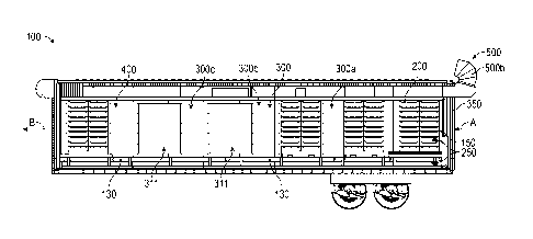
Referring to Figures 3A to 5, different views of cooling system 100 are
shown. Figure 3A is a front isometric view of cooling system 100. Figure 3B is
a rear
isometric view of cooling system 100. Figure 4 is a top internal view of
cooling
system 100. Figure 5 is a side cross-sectional view of an interior of cooling
system
100.
Cooling system 100 may be a container/trailer attached to a trailer chassis.
See, e.g., Figures 3A, 3B, and 5. In exemplary embodiments, cooling
container/trailer
350 may be approximately thirty five to forty feet long. In some embodiments,
container 350 may include a hard ground cover to hold an approximately 60,000
lb
mobile cooling container attached to a trailer chassis. However, cooling
system 100 is
not limited to this particular configuration, and containers and/or trailers
of other
suitable sizes / lengths / widths may be used in embodiments of the present
disclosure.
As indicated in Figure 7, in particular embodiments, container 350 may
include stainless steel airtight sections/chambers 200, 300 (300a, 300b,
300c), 400
dragged into and bolted within container 350. In this embodiment, gaskets may
be
used to seal each section with each other. Further, insulation may be
installed between
the outside of each steel section and an exterior cladding of the mobile
container 350.
Tracks may be positioned on opposing sides of each steel section to assist in
insertion
12
CA 03018084 2018-09-17
WO 2017/161324
PCT/US2017/023052
and installation of each section. In other embodiments, cooling container 350
may be
a box/chamber that is inserted and bolted into a standard reefer/box trailer
or placed
onto a flat deck trailer, such that produce packed in, for e.g. palletized
lugs, may be
placed into the unit 350 for cooling. For e.g., container 350 may be fit into
a fifty-
three-foot long reefer trailer. In yet other embodiments, container 350 may be
"Intermodal", and designed to be moved from one mode of transport to another
(e.g.
from ship, to rail, to truck).
In some embodiments, cooling system 100 may be integrated into existing
harvesting systems, packaging systems, and/or a building or other structure
for further
refrigeration, packaging, and processing. In an exemplary embodiment,
harvesting
system may be an Oxbo 7420 harvester that can output at least three pallets
150 of
produce every forty-five minutes. In other embodiments, cooling system 100 may
be
integrated into a semi-trailer system to act as a "factory in the field" that
performs
harvesting, processing, cooling, and/or packaging of produce at one location.
Cooling container/trailer 350 may include an opening in a front and back end
351, 352 of the container 350 to allow for insertion and removal of produce
packed in,
for e.g., palletized lugs/pallets 150. For e.g., one end opening of the
cooling container
350 may include a dock seal built into a frame of the container 350, so that a
standard
reefer trailer, smaller field trailer, forklift, and/or similar structure may
unload pallets
150 directly into the container 350 for cooling. An opposing end opening of
the
cooling container 350 may be configured to unload chilled produce 152 in
pallets 150
directly onto, for e.g., a fresh fruit packing line, a refrigerated trailer,
and/or an
opening in a refrigerated building. In some embodiments, a protruding,
airtight,
rolling door 122 may be attached to this opposing end opening of container
350. See,
e.g., Figure 3A. In other embodiments, each end opening of the container 350
13
CA 03018084 2018-09-17
WO 2017/161324
PCT/US2017/023052
adjacent to door 122 may include a plate, trailer door, or other structure to
cover up
the opening during transport. End openings of container 350 may therefore
allow for
increased versatility and adaptability of system 100 to different types of
processes.
Cooling system 100 may include connections/attachments to attach/plug in
system 100 to various other systems, including but not limited to cooling
systems,
power systems, etc. For e.g., cooling container 350 may be powered via
attachments
to a variety of connections to back up different ton units. In a particular
embodiment,
container 350 may be powered via attachments to a three-phase power source
that
may be, for e.g., a landline or generator, as well as a 25+ ton refrigerator
(Air
Conditioning Unit) that integrates with a PLC mounted within the container
350.
Referring to Figures 4 and 5, cooling container/trailer 350 of cooling system
100 may include at least a separated first staging section 200, second rapid
cooling
section 300, and third discharge section 400. In an exemplary embodiment,
first
section 200, second section 300, and third section 400 may be made from
stainless
steel. However, first section 200, second section 300, and third section 400
may be
made from other suitable materials, including any materials that can be
cleaned and
disinfected per applicable food processing rules and requirements.
As shown in Figure 4, first section 200, second section 300, and third section
400 are separated via swinging doors 122 or roll-up doors 122. Swinging doors
122
may be configured to separate each of the first, second, and third sections
200, 300,
400, while simultaneously allowing at least one pallet 150 containing produce
to be
easily conveyed from the first section 200 to the second section 300 to the
third
section 400. Alternatively, first section 200, second section 300, and third
section 400
may be separated via other suitable movable structures, e.g., flexible clear
plastic
flaps/doors or fabric rollup doors 122, to allow for produce to pass between
the
14
CA 03018084 2018-09-17
WO 2017/161324
PCT/US2017/023052
sections of container 350. In some embodiments, a rollup door 122 may be
fitted with
sensors that act to automatically open and shut the rollup door 122 as at
least one
pallet 150 is conveyed across the system 100.
At least one pallet 150 containing produce may be successively conveyed
from the first section 200 to the second and third sections 300, 400 of the
container
350 via a conveyor system 130. See, e.g., Figure 4. Conveyor system 130 may
include at least one conveyor/movable belt 136 longitudinally extending along
the
length of the mobile container/trailer 350 and across the first section 200,
second
section 300, and third section 400. In an exemplary embodiment, conveyor
system
130 may include a series of conveyors longitudinally extending along the
entire length
of the container 350/cooling system 100. In an embodiment, chain conveyors may
be
mounted inside a steel piping system within container 350. See, e.g., Figure
4. Chain
conveyors may vary in size and/or graduate into each other. As shown in Figure
4,
one conveyor may be located in first section 200, three conveyors may be
located in
second section 300, and one conveyor may be located in third section 400. In
an
alternative embodiment, conveyor system 130 may include at least seven five
foot
long conveyors extending along each of the first section 200, second section
300, and
third section 400 of the container 350.
As indicated in Figures 16-17, in embodiments, conveyors in conveyor
system 130 may be inserted into the floor of container 350 via conveyor guides
134
and welded to the floor of container 350. Conveyors 130 may be located within
a
single section 200, 300, 400 or may cross over into different sections 200,
300, 400.
Conveyor system 130 may be driven via connections to electric motors 132
mounted in container 350. As indicated in Figures 16-17, motors 132 may be
mounted on either side of conveyor system 130. In an exemplary embodiment,
five
CA 03018084 2018-09-17
WO 2017/161324
PCT/US2017/023052
motors 132 may independently control each conveyor in conveyor system 130. In
other embodiments, conveyor system 130 may be hydraulically driven or driven
via
other suitable systems. The speed of the conveyors in the conveyor system 130
may
be adjustable as needed. For e.g., conveyors in conveyor system 130 may move
up to
30 feet per minute. In an embodiment, speed of the conveyor system 130 may be
controlled via connections to a variable frequency drive (VFD) controlled by a
PLC
mounted within container 350. In an exemplary embodiment, speed of the
conveyor
system 130 may be controlled through an Allen-Bradley PowerFlex 525 AC Drive
via EtherNet/IP with an Allen-Bradley CompactLogixTM 5370 controller.
Referring back to Figures 4 and 5, first section 200 of cooling container 350
is
configured to act as a staging chamber and hold at least one pallet 150
containing
fresh harvested produce in a semi-cooled environment. In this embodiment,
first
section 200 is not ventilated with any ductwork. At least one pallet 150 may
be held
in the first section 200 prior to conveyance into the second section 300 via
the
conveyor system 130. In an exemplary embodiment, first section 200 holds two
pallets 150. See, e.g., Figure 4. Alternatively, first section 200 may hold
more or less
pallets 150. In an embodiment, first section 200 may be ten feet long.
However, first
section 200 may have a larger or smaller size.
Second section 300 of cooling container 350 is configured to receive at least
one pallet 150 containing fresh produce from the first section 200 and cool
the
produce. Particularly, second section 300 may be utilized as a cooling area
including
cooling mechanisms to cool the produce within the at least one pallet 150 to
an
optimal cooled temperature. In an exemplary embodiment, berries, such as
blueberries, in at least one pallet 150 may be cooled to an optimal
temperature of
approximately 50 to 55 degrees Fahrenheit. However, other types of produce may
be
16
CA 03018084 2018-09-17
WO 2017/161324
PCT/US2017/023052
cooled in the cooling system 100 to its corresponding optimal cooled
temperature. In
an embodiment, second section 300 may be twenty feet long. However, second
section 300 may be larger or smaller.
Although the optimal produce temperature is between about 50 to about 55
degrees, it may be desirable in some cases to cool the produce to below 50
degrees F.,
or even to just above freezing, such as to about 34 degree F. The mobile
cooling
container 350 can be configured to efficiently reduce produce to such
temperatures in
a short amount of time. When produce, such as fruit, is processed on a
production
line, it is sometimes desirable to provide the fruit in a near-frozen state,
the theory
being that near-frozen produce is harder and therefore more resistant to
bruising,
which can result from drops or other rough handling while on the production
line.
However, once fruit has been brought to a near frozen state, care must be
taken to
avoid allowing the fruit to warm up, which results in condensation and rapid
spoilage.
Additionally, for most purposes described herein, care must be taken to ensure
that
the produce remains at a temperature above freezing at all times; this is
because once
produce is frozen, it is considered "processed" and cannot be marketed or sold
as
"fresh.- In order to facilitate these particular purposes, the mobile
container 350 can
be configured or set (e.g. by a thermostat or other controller) to drop the
temperature
of the fruit to just above freezing, such as 34 degrees F, by the third
station 300c. The
almost-frozen fruit is then removed from the container 350 and introduced into
a
production line. Robots can be used at the end of the trailer to load the
fruit onto the
production line. The production line area is a discrete area from the loading
area and
the pack off area. A production line takes in fruit that is very close to
freezing and
runs it through to the pack line. Although the produce arrives in a near-
frozen
temperature, the ambient air in the working part of the production line can
optionally
17
CA 03018084 2018-09-17
WO 2017/161324
PCT/US2017/023052
be warmer, such as about 50 degrees F, because it only takes about 1-2 minutes
to
traverse a production line with modern sorting equipment. The short exposure
to the
higher temp would likely not result in condensation, the enemy for enhancing
spoilage. However, to avoid the risk of warming and condensation, the intake
and
discharge sections of the production line can be held near 34 degrees F.
Typically, the
boxed and packaged fruit is kept in the low 30s after being packed.
As shown in Figures 4 and 5, second section 300 includes a first cooling
station 300a, second cooling station 300b, and third cooling station 300c,
each of
which may hold at least one pallet 150. However, second section 300 may
utilize
more or less cooling stations to cool produce within pallets 150 being
transported
across system 100. Further, each cooling station within second section 300 may
hold
more or less pallets 150.
Second section 300 may include an internal-external cooling mechanism 500
to cool produce in at least one pallet 150. See Figures 3A and 5. Figure 6
illustrates
an example embodiment of the workings of internal-external cooling mechanism
500
in first cooling station 300a, second cooling station 300b and/or third
cooling station
300c.
Internal-external cooling mechanism 500 as disclosed in embodiments of the
present disclosure may include any forced air central systems, including but
not
limited to systems attached to ducts/ductwork, air handlers, air
terminals/vents
including supply air outlets and return or exhaust air inlets, etc. In an
embodiment,
cooling mechanism 500 may cool produce via connections to forced air
refrigeration,
whereby cooled/chilled air may be drawn through the produce and recycled via a
heat
exchanger. In this embodiment, container 350 may be attached via internal and
external ductwork to external forced air refrigeration equipment (see Figure
6), which
18
CA 03018084 2018-09-17
WO 2017/161324
PCT/US2017/023052
equipment may be a mechanical, expansion/compression type refrigeration system
where a compressed refrigerant gas may be passed into expansion coils. Water
may be
drawn from a retention sump and cascaded over the coils within a heat
exchanger, and
expanding refrigerant gas may draw heat from the water. Air may then be drawn
upward through the chilled water cascade to remove heat from the air, and the
resulting cooled/chilled air may then be pushed/forced into the container 350
through
inlet ducts 500a via fans mounted outside the container 350. See Figures 3A,
3B, and
6. Chilled air may be blown at the produce in pallet 150 (shown as direction A
in
Figure 6) to remove ambient heat from the produce, and the resulting warmed
air
may then be pulled back out and through return outlet ducts 500b (shown as
direction
B in Figure 6), and eventually cycled back through the externally located
water
cascade. The process may then be repeated until a desired/optimal reduction in
temperature of the produce is reached.
Internal-external cooling mechanism 500 may include a lightweight
detachable air inlet and outlet system attached to a track system mounted on a
top
exterior of container 350. See Figure 3A, 3B, 5, and 6. For e.g., two air
inlets 500a
may be positioned between two air outlets 500b, with the air inlets 500a and
outlets
500b mounted on a top exterior of container 350 adjacent to first section 200.
See
Figures 3A, 3B, and 6. As shown in Figures 3A, 3B, in embodiments, the four
air
inlets 500a and/or outlets 500b may constitute flexible ducts 500a, 500b that
attach
(via for e.g. hoses) to an external AC unit/refrigeration trailer such as for
e.g., a
Tranee AC unit. See Figure 6. In exemplary embodiments, the four air inlets
500a
and/or outlets 500b may protrude up to a foot and a half out from the frame of
the
container 350. See Figures 3A, 3B, and 5.
19
CA 03018084 2018-09-17
WO 2017/161324
PCT/US2017/023052
In exemplary embodiments, RA inline fans 600a, 600d may be placed outside
container 350 between an external AC/refrigeration unit 500 and container 350.
See
Figure 6. Inline fans 600a, 600d may have a variable speed and rotation of
inline fans
may be controlled via Variable Frequency Devices (VFDs) connected to a PLC
mounted within container 350. In an exemplary embodiment, fans may be inline
fans
offered by Greenheck Fan Corporation.
Placement of inline fans and external AC unit may be dependent on wind
direction. For e.g., inline fans and attached AC unit and generator may be
placed
downwind of container 350 to avoid exhaust fumes from a diesel generator.
Inline
fans are utilized in order to increase the Cubic Feet per Minute (CFM) in
container
350 by ensuring that air moves quickly though the flexible duct inlets 500a
and
outlets 500b mounted adjacent to the first section 200 and external to the
container
350. See Figures 3A, 3B, and 5. It is important to move air quickly though the
flexible ducts and into insulated ducts in the container 350 since heat can be
lost as
the air is pushed through these flexible ducts.
As shown in Figure 5, each of first cooling station 300a, second cooling
station 300b, and third cooling station 300c may include at least one duct
opening 311
for attachment of ductwork to perform cooling mechanism 500 in second section
300.
In an exemplary embodiment, at least one duct opening 311 may be an
approximately
50-inch x 64-inch sized rectangular opening. However, at least one duct
opening 311
may have other suitable sizes or configurations to assist in cooling of
produce and for
attachment of different sized cooling systems. In an exemplary embodiment,
insulated
ducts may be inserted into the container 350 and welded to duct openings 311
in a
stainless steel metal frame of each station 300a, 300b, 300c of second section
300.
CA 03018084 2018-09-17
WO 2017/161324
PCT/US2017/023052
Features can be provided to improve accessibility to the system 100, 1000,
such as for maintenance of the various components. Sidewalls of the mobile
container 350 can be provided with access openings at strategically selected
locations
along the length of the mobile container 350. For example, an access opening
can be
provided adjacent to any or all of the cooling stations 300a, 300b, 300c. The
access
openings allow access to components of the cooling system for monitoring of
operations and maintenance of components. The access openings can be provided
with doors for selectively sealing and unsealing the openings to provide
access to the
interior of the mobile container 350. The doors can be various forms, such as
roll-up,
sliding, hinged, and the like, depending on the needs and operating
conditions. Since
openings typically reduce insulation, the openings and doors may be provided
with air
tight seals, such as through the use of gaskets and compression latches.
In particular embodiments, internal-external cooling mechanism 500 may
include chilled air blown at high velocity over produce in at least one pallet
150 to
take ambient heat out of the produce. See, e.g, Figures 4 and 6. As the
berries may be
"piled" as high as six inches in the pallets 150, the blast of air being blown
at the
produce must be strong enough to reach the center of each pallet 150. To
accomplish
this strong air flow, chilled air may be blown at produce in varying speeds
and from
opposing sides of the produce as it is transported across the second section
300. In
some embodiments, chilled air may have a temperature of +/- 5 degrees of a
preset
targeted exit temperature for when the produce exits the second section 300.
In other
embodiments, the produce may simply be exposed to colder air with a
temperature
much lower than a targeted exit temperature so as to speed up the cooling
process in
system 100.
21
CA 03018084 2018-09-17
WO 2017/161324
PCT/US2017/023052
As shown in Figures 4 and 5, at least one pallet 150 may be located at first
cooling station 300a. Internal-external cooling mechanism 500 in first cooling
station
300a may include cooled air outputted via vents located on a first side of the
first
cooling station 300a to cool produce in at least one pallet 150, with ambient
heat from
the produce being exhausted out via vents located on an opposing second side
of the
first cooling station 300a.
At least one pallet 150 may then be moved down to second cooling station
300b via conveyor system 130. Cooling mechanism 500 in second cooling station
300b may include cooled air outputted via vents located on a first side of the
second
cooling station 300b to cool produce in at least one pallet 150, with ambient
heat from
the produce being exhausted out via vents located on an opposing second side
of the
second cooling station 300b.
At least one pallet 150 may then be moved down to third cooling station 300c
via conveyor system 130. Cooling mechanism 500 in third cooling station 300c
may
include cooled air outputted via vents/ducts located on a first side of the
third cooling
station 300c to cool at least one pallet 150, with ambient heat from the
produce being
exhausted out via vents located on an opposing second side of the third
cooling station
300c.
In exemplary embodiments, input and output vents may be positioned on
opposing sides of adjacent stations 300a, 300b, 300c in an alternating,
staggered
configuration. As shown in Figure 4, vents on the first and second side of the
second
cooling station 300b are positioned on the same side as vents on the second
and first
side of the first cooling station 300a and third cooling station 300c,
respectively.
Alternatively, other configurations for cooling may be used in cooling system
100.
22
CA 03018084 2018-09-17
WO 2017/161324
PCT/US2017/023052
Vents/ducts in the first side of the first, second, and third cooling stations
300a, 300b, 300c may each include at least one mechanized damper controlled by
a
PLC via an analog connection. At least one mechanized damper may close and
open
to control how much air is entering/flowing into the first, second, and third
cooling
stations 300a, 300b, 300c and onto produce in at least one pallet 150.
Vents/ducts in
second side of first, second, and third cooling stations 300a, 300b, 300c may
each
include at least one air velocity sensor configured to communicate with the
PLC 260
connected to VFDs of inline fans 600a, 600d described herein to instruct the
fans
600a, 600d to speed up to facilitate pulling of air up and out the system 100.
Once cooling mechanism 500 of second section 300 cools produce in at least
one pallet 150 to a desired optimal temperature, at least one pallet 150
containing
chilled produce may be moved to third section 400 of container 350 via
conveyor
system 130. Third section 400 may include a cooling mechanism 500
substantially
similar to cooling mechanism in second section 300. Particularly, third
section 400
may act as an outlet chamber and maintain chilled produce in the at least one
pallet
150 at the desired/exit temperature via cooled air outputted via vents located
on
opposing sides of the third section 400 onto the at least one pallet 150.
Further, third
section 400 may also include at least one duct opening 311 for attachment of
ductwork to perfolin cooling mechanism in third section 400. See, e.g., Figure
5. In
an exemplary embodiment, insulated ducts may be inserted into the container
350 and
welded to duct openings 311 in third section 400.
Third section 400 may maintain the chilled produce in the at least one pallet
150 at the optimal temperature until it is ready for unloading and
transportation to
another area for further refrigeration and processing. In some embodiments, at
least
one pallet 150 containing chilled produce may be removed from the third
section 400
23
CA 03018084 2018-09-17
WO 2017/161324
PCT/US2017/023052
via an un-motorized conveyor ramp to a cold storage location where it may be
held at
the exit temperature. Cold storage location may be a cold/refrigerated reefer
trailer
and/or other movable or non-movable structures having the capability to store
and
maintain the produce at a desired temperature.
In alternative embodiments, at least one pallet 150 containing chilled produce
may be removed from container 350/system 100 via other mechanisms, e.g.,
automated conveyors, lifts, etc. In some embodiments, a user may physically
open a
door adjacent to third section 400 to accept at least one pallet 150
containing chilled
produce. In other embodiments, a user may automatically open the door via
systems
such as screw drive, belt drive, and/or chain drive garage door opener
systems. Once
the door is open, at least one pallet 150 may be removed off conveyor system
130 in
the third section 400 by a user via for e.g., a hand pallet jack.
Cooling system 100 may further include a sensor feedback system 250
including at least one sensor placed within the at least one pallet 150
containing
produce and/or attached to an interior of container 250. See, e.g., Figure 4.
At least
one sensor may be but is not limited to an air velocity sensor described
herein,
temperature sensor, humidity sensor, position sensor such as a photoelectric
sensor
(photo eye), proximity sensor, and/or pressure sensor. At least one sensor may
further
be any device (such as a load sensor/cell further described herein) used to
measure
and track weight of pallet 150 containing produce.
Sensor feedback system 250 may be automated or operated by a user.
Sensor feedback system 250 may be a dynamic, real-time system configured
to continuously measure, track, and obtain feedback/information regarding the
produce within the at least one pallet 150 being transported through the
container
350/cooling system 100. As described herein, sensor feedback system 250 may
output
24
CA 03018084 2018-09-17
WO 2017/161324
PCT/US2017/023052
this information directly to a PLC and/or computer via hardwired and/or
wireless
connections, which information may then be stored and/or outputted to a web
address/user interface accessible by a user computing device such as, e.g., a
mobile
device, and/or directly to a user computing device. See Figures 1 and 2.
In particular embodiments, sensor feedback system 250 may include
temperature monitoring devices/sensors placed within at least one pallet 150
containing produce. Temperature sensors may be placed at various locations
within
the at least one pallet 150. For e.g., temperature sensors may be placed
within bins of
produce located in the middle and/or outer edges of at least one pallet 150.
In
embodiments, each pallet 150 may include at least four temperature sensors,
with
each pallet 150 being approximately sixty inches tall. In an exemplary
embodiment,
temperature sensors may be an RFD temperature sensor 705 manufactured by Phase
W Engineering, Inc. Temperature sensors 705 may be used to obtain information
regarding produce, including but not limited to the exact temperature of
produce in
the at least one pallet 150, the specific location of the produce with that
temperature
within the at least one pallet 150, as well as the location of the at least
one pallet 150
itself.
In various embodiments, sensor feedback system 250 may include eleven
position sensors to track location of at least one pallet 150 on a conveyor
system 130.
For e.g., photoelectric sensors (photo eyes) may be used to determine the
distance,
absence, and/or presence of at least one pallet 150 by using a light
transmitter
(generally infrared) and a photoelectric receiver. Photo eyes may be removably
mounted on one side of container 350 and wired into an electrical box attached
to
conveyor system 130. In an exemplary embodiment, one photo eye may be mounted
at the beginning and end of each of five conveyors in a conveyor system 130,
as well
CA 03018084 2018-09-17
WO 2017/161324
PCT/US2017/023052
as at the entrance of the container 350 to track whether at least one pallet
150 has
entered the container 350. In this embodiment, at least one pallet 150 passing
the first
photo eye may indicate that it is fully on a conveyor, and at least one pallet
150
passing any subsequent photo eyes may indicate its corresponding position on
the
conveyor system 130.
In some embodiments, sensor feedback system 250 may further include
capacitive proximity switches/sensors mounted in container 350 to act as
secondary
sources for reading whether there is any weight on the conveyors in conveyor
system
130, thereby allowing a user to determine the location of at least one pallet
150 on
conveyor system 130. Furthermore, utilizing the photo eyes and/or capacitive
proximity sensors may allow a user to determine when at least one pallet 150
is
transferred between conveyors 136 in conveyor system 130, and therefore, when
to
turn these conveyors on and off.
Sensor feedback system 250 may also include humidity sensors attached to an
interior of the container 350 to track the humidity within the container 350.
In a
particular embodiment, one humidity sensor may be placed in each of the first
cooling
station 300a, second cooling station 300b, third cooling station 300c, and
third section
400. Particularly, one humidity sensor may be placed in the internal walls of
ducts in
each of the first cooling station 300a, second cooling station 300b, third
cooling
station 300c, and third section 400. In this embodiment, each humidity sensor
may be
located on one side of container 350 and wired into an electrical box attached
to
conveyor system 130. In alternative embodiments, any number of humidity
sensors
may be located in any location within each section 200, 300, 400 of the
container 350.
In exemplary embodiments, sensor feedback system 250 may include an RFID
feedback system whereby load/weight, temperature and/or humidity sensors may
send
26
CA 03018084 2018-09-17
WO 2017/161324
PCT/US2017/023052
relevant weight, temperature and/or humidity information via wired and/or
wireless
connections to an RFID reader 701 attached to an interior of container 350.
RFID
reader may be configured to pull relevant sensor information via a wireless
Near Field
Communication (NFC) connection. In embodiments, RFID reader may be connected
(wirelessly or by wired connections) to a PLC such that the RFID reader may
transmit
relevant temperature and/or humidity information to the PLC. PLC may then
transmit
the temperature and/or humidity information via a Wi-Fi connection to a web
address/user interface accessible by a user computing device 282 such as for
e.g., a
mobile device. See, e.g., Figure 1. In an exemplary embodiment, RFID reader
701
may be the SIMATIC RF67OR device from Siemens AG.
In a particular embodiment, an RFID reader antenna 703 may wirelessly read
RFID tags 705 inserted/placed within the at least one pallet 150 to determine
the
current temperature of the produce within the at least one pallet 150. This
temperature
reading may be received and stored by the RFID reader 701, which RFID reader
701
may then transmit the reading to a PLC 260 connected to the RFID reader 701.
In
other embodiments, Wi-Fi temperature and/or humidity sensors may wirelessly
transmit the reading directly to a PLC. In either embodiment, the PLC may
output the
rea701701ding to a web address/user interface accessible by a user computing
device.
See, e.g, Figure 1. A recurring RFID/ electronic feedback loop may then track
the
location of the at least one pallet 150 and/or monitor the amount of cooling
in the
container 350 to ensure temperature of the produce is consistent with an
expected/preset temperature for produce upon exiting the second section 300
and/or
third section 400, and to prevent freezing.
Sensor feedback system 250 may further be used to control the movement of
the conveyor system 130 described herein based on the temperature measurement
27
CA 03018084 2018-09-17
WO 2017/161324
PCT/US2017/023052
being tracked as at least one pallet 150 is moved down cooling container 350.
Sensor
feedback system 250 may control the conveyor system 130 via connections to the
PLC 260 mounted in container 350. In embodiments, the speed of the conveyor
system 130 may be varied based on the size of the pallet 150 and temperature
of the
.. produce within the pallet 150 upon entrance into the first section 200 of
container
350.
In exemplary embodiments, different run options may be utilized to move at
least one pallet 150 across container 350 via conveyor system 130 connected to
the
PLC 260 described herein. In one embodiment, at least one pallet 150 may be
continuously inserted into and moved through the container 350 such that at
least one
pallet 150 traverses the entirety of the container 350 in a range of
approximately
fifteen to forty five minutes. In an embodiment of this "continuous" cooling
embodiment, at least one pallet 150 may be moved through the second section
300 at
a rate of 1 minute/foot in a slow but consistent manner. In other embodiments,
system
100 may cool approximately three pallets 150 every forty-five minutes.
In another "stop and go" embodiment, at least one pallet 150 may be
immediately moved to first cooling station 300a where cooled air may be
outputted
via vents/ducts onto produce in the at least one pallet 150. Temperature
sensors in
sensor feedback system 250 may then measure and track temperature of produce
in at
least one pallet 150 until temperature reaches an optimal temperature, at
which point
at least one pallet 150 may be immediately moved to second cooling station
300b, and
then successively to third cooling station 300c and third section 400 for
additional
tracking and cooling.
In yet another "accrual" embodiment, a reefer may not be available for
unloading at least one pallet 150 containing chilled produce, so multiple
pallets 150
28
CA 03018084 2018-09-17
WO 2017/161324
PCT/US2017/023052
containing chilled produce may be loaded onto conveyors in conveyor system 130
and
accrued within container 350. This embodiment allows a user to cool and store
multiple pallets 150 of produce even if options to unload the pallets 150 are
not yet
available.
In embodiments, once the at least one pallet 150 is brought to the desired
exit
temperature and held in the third section 400 of the container 350, an
operator / user
outside of the cooling container 350 may assist in ejection/removal of the at
least one
pallet 150 as described herein. In other embodiments, sensor feedback system
250
may be automatically preset via RF1D controls to output the at least one
pallet 150 on
a timed basis by opening the automatic roll up door 122 when it is at the
optimal
temperature.
Sensor feedback system 250 may be powered via connections to a power
source located in the container 350. Power source may include other forms of
power,
e.g., a battery, direct wired connection into the container 350 itself, etc.
As shown in Figures 14 and 15, cooling system 100 may further include a
visual/lighting system 180 located on an exterior of the container 350. As
shown in
Figure 14, the visual system 180 may be provided on the output opening end 352
of
the mobile container 350. As shown in Figure 15, the visual system 180 can be
provided on the input opening end 351 of the mobile container 350. Visual
system
180 may be mounted onto container via either permanent or non-permanent
attachment mechanisms, for e.g., an adhesive. Visual system may be controlled
by a
PLC mounted in container 350. In embodiments, visual system may include red
and
green lights 182, 184, 186 configured to provide notification to an operator
to load a
new pallet 150 into the container 350. In this embodiment, visual system may
show
the red light 182 to indicate to the operator to hold off on loading/unloading
the pallet
29
CA 03018084 2018-09-17
WO 2017/161324
PCT/US2017/023052
150 and a green light 186 to indicate to the operator to proceed to
load/unload the
pallet 150. In other embodiments, red, yellow, and green lights 182, 184, 186
may be
mounted to the outside of each of the first and third sections 200, 400. For
e.g., the
three lights 182, 184, 186 may each be mounted on opposing sides of a rolling
door
.. described herein attached to the outside of the third section 400. In this
embodiment,
visual system may show the red light to indicate to the operator that a pallet
150 is
inside the container 350 but not ready for unloading, a yellow light to
indicate that the
pallet 150 is moving into the third section 400 for unloading, and a green
light to
indicate to the operator that the pallet 150 is ready for unloading. In some
embodiments, red, yellow, and green lights may be a row of red, yellow, and
green
LEDs (light-emitting diodes). Alternatively, cooling system may include other
suitable visual, audio, and/or audiovisual systems to notify a user to load
pallets 150
in the container 350.
Figures 7 to 10 show different views of cooling system 1000, an alternative
embodiment of cooling system 100. Figure 7 is a front isometric view of
cooling
system 1000. Figure 8 is a top internal view of cooling system 1000. Figure 9
is a
side cross-sectional view of an interior of cooling system 1000. Figure 10 is
a rear
cross-sectional view of an interior of cooling system 1000.
Cooling system 1000 may have substantially the same features as cooling
system 100, including but not limited to container 350 (and first section 200,
second
section 300, first cooling station 300a, second cooling station 300b, third
cooling
station 300c, and third section 400), conveyor system 130, sensor feedback
system
250, at least one pallet 150, PLC, and computer sending produce and/or
container 350
data to a user and/or databases. See Figures 1 and 2.
CA 03018084 2018-09-17
WO 2017/161324
PCT/US2017/023052
As shown in Figures 9 and 10, cooling system 1000 includes a scale 700
integrated/installed with (for e.g., a chain drive of) conveyor system 130 and
used to
measure weight of the at least one pallet 150 upon entering the system 1000.
Scale
700 may be any type of load cell/sensor that may be used to measure weight of
at
least one pallet 150. Load cell/sensor may be any physical element/transducer
that
may translate pressure (force) into an electrical signal. In embodiments, load
cells/sensors of scale 700 may be connected to and send relevant weight
information
to PLC and/or computer in system 1000. See, e.g., Figure 1. The computer may
be
configured to output this weight information to a web address/user interface
accessible by a user from any user computing device (see, e.g., Figure 1)
and/or to
continuously receive and store the weight inforniation in a database in
computer
storage and/or in a database in the cloud (see, e.g., Figure 2)
Further, as shown in Figures 6 to 8, this embodiment of cooling system 1000
includes fabric rollup doors 122 that separate first section 200, second
section 300,
and third section 400. Rollup door 122 may be fitted with sensors that act to
automatically and quickly open and shut the rollup door 122 as at least one
pallet 150
is conveyed across the system 1000 so as to prevent leakage of cold air from
each
section 200, 300, 400.
Unlike cooling system 100, which includes an internal-external cooling
mechanism 500, cooling system 1000 includes a completely internal cooling
mechanism 600 installed within container 350. This particular configuration of
internal cooling mechanism 600 allows for elimination of all ductwork
(including
inlets 500a and outlets 500b) in internal-external cooling mechanism 500,
thereby
allowing for faster and more optimal cooling of the produce in at least one
pallet 150.
31
CA 03018084 2018-09-17
WO 2017/161324
PCT/US2017/023052
Figure 11 is an isometric view of an example embodiment of a cooling station
300a, 300b, 300c of second section 300 of cooling system 1000 that employs a
"closed loop" based internal cooling mechanism 600. Figure 12 is a front view
of
cooling station 300a, 300b, 300c shown in Figure 11 illustrating the workings
of
internal cooling mechanism 600.
As shown in Figures 11 and 12, cooling mechanism 600 may be an internal
air handler system that includes cooling fans 600a placed adjacent to
cooling/condenser refrigeration coils 600b in an interior of each cooling
station 300a,
300b, 300c such that chilled air is forcefully blown at at least one pallet
150 to
thereby quickly cool produce in at least one pallet 150.
Refrigeration coils 600b and cooling fans 600a of cooling mechanism 600
may be utilized in substantially the same manner to cool produce in at least
one pallet
150 as the external coils and fans in the internal-external cooling mechanism
500 as
described herein, but with the entire cooling process being performed
internally
within each cooling station 300a, 300b, 300c. See, e.g, Figure 12.
In an exemplary embodiment, a row of cooling fans 600a may be installed in a
first side of an interior of each cooling station 300a, 300b, 300c.
Cooling/condenser
refrigeration coils 600b may be installed in interior of each respective
cooling station
300a, 300b, 300c such that coils 600b are adjacent to both cooling fans 600a
and at
least one pallet 150. Opposing ends of chilled fluid lines 600e may be
attached to
coils 600b and to a portable commercial chiller 500. See Figure 12. Commercial
chiller 500 may be located external to container 350 or, in an exemplary
embodiment,
may be installed to a bottom exterior surface of container 350. As shown in
Figure 12,
chilled fluid lines 600e include an input and return line.
32
CA 03018084 2018-09-17
WO 2017/161324
PCT/US2017/023052
In exemplary embodiments, fluid may be chilled in the commercial chiller and
then introduced into each cooling station 300a, 300b, 300c via chilled fluid
lines
600e. Fluid may be water or glycol based. A damper system can be used to
control the
air along with the fans. For certain products or climates, it may be necessary
or
helpful to introduce or exhaust moisture laden air from the container 350 or
individual
compartments 200, 300, 400 thereof. Fans 600a may then be activated to blow
air at
coils 600b to thereby allow for chilled air in the range of approximately 32
to 50
degrees to be blown at produce in at least one pallet 150 in direction A to
remove
ambient heat from the produce. See Figure 12. Warmed air from the produce may
then be pushed up within each cooling station 300a, 300b, 300c via return air
duct
600c and return air fans 600d in direction B and recirculated/cycled back in
direction
C towards cooling fans 600a for re-cooling. This process may be repeated until
a
desired/optimal reduction in temperature of the produce is reached.
Cooling fans 600a and return air fans 600d may include any type of inline fans
having a variable speed and a rotation that may be controlled via VFDs
connected to a
PLC mounted within container 350.
Each station 300a, 300b, 300c and at least one pallet 150 may include sensor
feedback system 250 described herein. Sensor feedback system 250 and related
sensors may be used to measure, track, and send relevant temperature
information
regarding the produce in at least one pallet 150 as well as regarding the air
being
circulated within each station 300a, 300b, 300c. Sensors may continuously
provide
this information to PLC and/or computer installed within container 350, which
information may be used to provide feedback and control cooling of at least
one pallet
150, including control of amount of chilled fluid entering each station 300a,
300b,
300c, and variability of speed of cooling fans 600a and return fans 600d.
33
CA 03018084 2018-09-17
WO 2017/161324
PCT/US2017/023052
In exemplary embodiments, cooling mechanism 600 may have a similar
alternating, staggered configuration as internal-external cooling mechanism
500
described herein. Fans 600a and coils 600b in first cooling station 300a and
third
cooling station 300c may be positioned in an opposing side to fans 600a and
coils
600b in second cooling station 300b. See Figure 8. Similarly, return air ducts
600c
and return air fans 600d in first cooling station 300a and third cooling
station 300c
may be positioned in an opposing side to return air ducts 600c and return air
fans
600d in second cooling station 300b. See, e.g., Figures 8 and 12.
Alternatively, other
configurations for cooling may be used in cooling system 1000.
Figure 13 is a flowchart showing cooling systems 100, 1000 as described
herein using sensor feedback system 250 as described herein. Figure 13A is a
flowchart showing a temperature reading process of sensor feedback system 250
as
described herein. Cooling systems 100, 1000 and sensor feedback system 250
described in Figures 13 and 13A may be implemented using the apparatuses,
systems
and methods described herein, including various embodiments thereof. As shown
in
Figure 13, cooling systems 100, 1000 may include the following steps.
At least one pallet 150 containing freshly harvested produce may be inserted
into the first section 200 of container 350 described herein and held in a
semi-cooled
environment. In an embodiment, scale 700 may then weigh at least one pallet
150 and
send this weight information to computer and/or PLC, which information may
then be
outputted to local storage and/or cloud-based databases described herein.
At least one pallet 150 may then be conveyed via conveyor system 130
described herein to first cooling station 300a of second section 300 described
herein.
Chilled air in a temperature range of approximately 32 to 50 degrees may then
be
outputted onto the at least one pallet 150 to cool produce in the at least one
pallet 150.
34
CA 03018084 2018-09-17
WO 2017/161324
PCT/US2017/023052
In exemplary embodiments, blueberries within at the least one pallet 150 may
be
cooled to an optimal temperature of approximately 50 to 55 degrees.
As shown in Figure 13A, sensor feedback system 250, including temperature
sensors, may then start an RFID read process to determine temperature of
produce
within at least one pallet 150. In this embodiment, an RFID reader antenna may
read
tags inserted/ placed within the at least one pallet 150 to determine current
temperature of the produce within the at least one pallet 150. In other
embodiments,
sensor feedback system 250 may utilize a Wi-Fi connection to wirelessly and
continuously communicate information regarding produce from wireless
temperature
sensors to a PLC mounted in container 350. In embodiments, temperature sensors
may send temperature readings obtained from produce to the PLC, which PLC may
then store and transmit this information locally to a computer connected to
the PLC
and mounted in container 350. Computer may then output this temperature
reading to
a web address/user interface accessible by a user of a user computing device
such as
for e.g., a mobile device. Computer may also output this reading to local
and/or cloud-
based databases.
PLC may use this information received regarding the produce to determine
whether to speed up the movement of the at least one pallet 150 containing
produce
on the conveyor system 130 or slow it down so that the produce will be cooled
for a
longer time frame. Although a user may directly control the AC unit to adjust
the
cooling temperature, the PLC may also determine if dampers described herein
mounted in the container 350 should open and close to allow more or less air
flow, as
well as whether inline fans located outside the container 350 should spin
faster or
slower and thereby increase or decrease CFMs in system 100. A user who wishes
to
change the temperature of the produce may monitor the webpage and turn the AC
unit
CA 03018084 2018-09-17
WO 2017/161324
PCT/US2017/023052
down or up. In an exemplary embodiment, the goal/optimal temperature may be
set
through the web address/user interface, and the conveyors in conveyor system
130,
fans and/or dampers may be controlled by the PLC based on that goal regardless
of
the temperature of the AC unit.
If the temperature reading on the tags is not at an optimal level (an optimal
level being, for e.g., blueberries at a temperature of approximately 50 to 55
degrees),
then sensor feedback system 250 may wait a minute and repeat the process by
continuing to read tags in the at least one pallet 150 via the RF1D reader
antenna to
determine temperature of the produce. In embodiments, sensor feedback system
250
may continue to send the temperature information to local storage and/or cloud-
based
databases described herein.
On the other hand, if the temperature reading on the tags is at the optimal
level, then the at least one pallet 150 may then be transported to second
cooling
station 300b described herein via the conveyor system 130. See Figure 13.
Chilled air
in a temperature range of approximately 32 to 50 degrees may again be
outputted onto
the at least one pallet 150 to cool produce in the at least one pallet 150.
Temperature
of produce within the at least one pallet 150 in the second section 300 may
then be re-
determined/evaluated via the steps of the sensor feedback system 250 described
herein. See Figure 13A. Sensor feedback system 250 may then resend the
temperature information to local storage and/or cloud-based databases
described
herein.
At least one pallet 150 may then be transported to third cooling station 300c
described herein via the conveyor system 130. Chilled air in a temperature
range of
approximately 32 to 50 degrees may then be outputted onto the at least one
pallet 150
to cool produce in the at least one pallet 150. Temperature of produce within
the at
36
CA 03018084 2018-09-17
WO 2017/161324
PCT/US2017/023052
least one pallet 150 in the third section 400 may then be re-
determined/evaluated via
the sensor feedback system 250 described herein. See Figure 12A. Sensor
feedback
system 250 may then resend the temperature information to local storage and/or
cloud-based databases described herein.
At least one pallet 150 may then be conveyed from the second section 300
onto a third section 400 via the conveyor system 130. Third section 400 may
maintain
the chilled produce in the at least one pallet 150 at the optimal temperature
prior to
unloading.
Embodiments provide a method for cooling produce. Methods may include
using the cooling systems 100, 1000 described herein, including container 350,
conveyor system 130, and sensor feedback system 250. In an exemplary
embodiment,
the method includes inserting at least one pallet 150 containing produce into
the
particular embodiment of cooling systems 100, 1000. In some embodiments, the
weight of the at least one pallet 150 may be measured and tracked via scale
700 of
sensor feedback system 250. The method includes transporting the produce in
the at
least one pallet 150 from the first section 200 of the container 350 to the
second
section 300 of the container 350 via the conveyor system 130. The method
includes
cooling the produce within the at least one pallet 150 to an optimal
temperature via
internal-external cooling mechanism 500 and/or internal cooling mechanism 600
described herein installed within the second section 300, continuously
measuring and
tracking the temperature of the produce within the at least one pallet 150 via
the
sensor feedback system 250 while the at least one pallet 150 is conveyed along
the
second section 300 to ensure the produce remains at the optimal temperature;
and
transporting the at least one pallet 150 from the second section 300 to the
third section
37
CA 03018084 2018-09-17
WO 2017/161324
PCT/US2017/023052
400 via the conveyor system 130 for maintaining the produce at the optimal
temperature prior to unloading.
Harvest-to-Sale Data Collection Systems
Special harvest-to-sale data collection systems 1001, 1001A will now be
described. It is an objective of these systems 1001 to provide data collection
and
usage solutions that will increase visibility and logistical support for all
players in the
supply chain, including fanner, packer, marketer, wholesaler, retailer, and
consumer,
which increases market efficiencies. The systems are configured to use the
produce
data for material requirements planning (MRP), particularly in certain stages,
such as
.. packing. It is also an objective of the systems to provide enhanced data
collection and
presentation about the "cold chain" to all participants in the "cold chain" of
produce,
including consumers at the end of the process. A cold chain is a temperature-
controlled supply chain. An unbroken cold chain is an uninterrupted series of
refrigerated production, storage and distribution activities, along with
associated
equipment and logistics, which maintain a desired low-temperature range. Under
conventional produce systems, available cold chain data is segregated within
particular participants, such as farms, pack houses, grocery wholesalers, and
grocery
retailers. As a result, comprehensive cold chain data is not available to all
participants.
Additionally, cold chain data is not available to end consumers of the
produce. It is an
object of the invention to provide integrated systems that collect and provide
relevant
cold chain data to all market participants, including end consumers, from the
point of
harvest to the point of sale.
The robust real-time data collection processes described herein provide the
basis for an application service provider (ASP) application specific to
produce data.
38
CA 03018084 2018-09-17
WO 2017/161324
PCT/US2017/023052
By collecting and uploading harvest-to-sale data into an ASP app, the system
1001,
1001A is able to control and profit from the data. Different players in the
supply chain
and cold chain are able to mine and parse the produce specific data to support
their
specific needs. For example, packers use weight and volume data to staff and
supply
the packing operation; marketers use other aspects of the data to advertise to
and
connect with potential buyers; wholesalers and grocery stores make purchase
decisions based on factors such as source, produce variety, cold chain
integrity, and
volume; and end consumers use cold chain data to verify that they are buying a
quality product.
The ASP app provides market participants with access to the data over a
network, such over through a standard HTTP protocol. Different users can be
provided with different levels of access through the ASP app, such as access
to all or
some subsets of data, access to write or to read-only, or ability to download
or
manipulate selected data. Pricing can be based on accessibility level, amount
of usage,
or other factors. The ASP app can provide specialized and powerful analytics
functions to small-to-medium sized businesses that would otherwise not have
access
to such information. An ASP app reduces the cost of distributing software, and
allows
for enhanced features such as security, system wide software updates, and
technical
support to users.
It should be appreciated that these harvest-to-sale data collection systems
1001, 1001A can be used independently of the previously described cooling
systems
100, 1000. However, as will be discussed below, the cooling systems 100, 1000
described herein can be incorporated into certain steps of the harvest-to-sale
systems
1001 to enhance the quality of the produce or provide automatic data
collection, and
thus improve both the quality and quantity of the data used in the systems
1001.
39
CA 03018084 2018-09-17
WO 2017/161324
PCT/US2017/023052
Independent Remote Packer Model
Figure 18 presents a schematic flow of processes in what can be referred to as
an independent remote packer model system 1001. As indicated above, this
system
can be provided in the form of an ASP app. In the independent remote packer
model
1001, produce 152 is being acquired from a third party that is not directly
linked into
a data collection system. As will be discussed below, the system 1001 provides
means
for loading produce data into the system 1001 for future use. The system 1001
saves
the data to a database in the cloud 2000 for use in marketing and selling
produce 152
to wholesalers, retailers and end consumers.
As shown in Figure 18A, the produce 152, such as blue berries, is harvested
1002 using known harvesting methods. Once the produce 152 has been harvested,
it is
brought to a selected loading destination 1004. While in the loading
destination 1004,
initial data is collected. At this point in the process, the data is likely to
consist of
weight and incoming produce temperature, but other data, such as ambient air
temperature, humidity, date, time of day, farm of origin, variety, field
location/block
location, local weather conditions, and the like could also be collected.
If the produce 152 is loaded to a conventional loading destination 1021, data
about the produce is entered manually into the system 1022. Manual data entry
can be
done using a conventional input means on a computer or mobile device, such as
a
keyboard or keypad. User friendly screens and prompts can be programmed into
the
system. However, if the produce 152 is loaded to a specialized data collection
cooling
system 100, 1000, such as the mobile field cooling system described herein,
the
produce specific data is automatically collected by the various sensors
previously
described herein. The produce specific data is collected in digital form and
the system
1001 is programmed to automatically pull the digital data into the system
1001, as
CA 03018084 2018-09-17
WO 2017/161324
PCT/US2017/023052
indicated in step 1012. Hybrids of manual and automatic collection can be
provided,
such as options for manually selecting which data sets will be automatically
pulled
into the system 1001.
Data can be corrected manually in the system, such as at the pack house,
.. where the fruit is sorted and graded, or anywhere else in the system where
data
updates or corrections are needed. Once the initial produce data has been
collected, it
is uploaded to a database 1030. While different forms of databases could be
used,
current technology makes a database in the cloud 2000 particularly efficient
and well-
suited for the system 1001. For example, system 1001 software interface in the
folin
of a program or application ("app") for a smart phone, tablet, or other
computer can
be downloaded by the independent harvester. In most applications, it is
anticipated
that data will be made available through the Internet, such as in an
interative ASP
application, as discussed above. Once the initial produce data 1030 is in the
system
1001, the app interfaces with the system 1001 to upload the data 1030 to the
database
2001 in the cloud 2000 for future use. While proprietary systems could be used
for
data collection, such as private satellite transmission, such systems are
likely to be
expensive and complicated compared to use of the cloud 2000. Appropriate
security
protections are integrated into the system 1001 to eliminate or reduce the
risk of
hacking and misappropriation of produce data.
Once data 1030 transmission is complete, the produce 152 is transported to a
pack house 1100. Transportation will ordinarily start with a truck used to
transport
produce from the field, but may involve other means of transport, such as
trains or
boats, prior to reaching the pack house. The precise vehicle is not
determinative,
although the vehicle or vehicles will ideally be refrigerated. However, the
system is
ideally equipped to track the produce during transport to the pack house 1100,
since a
41
CA 03018084 2018-09-17
WO 2017/161324
PCT/US2017/023052
primary objective of the system is to track produce specific data all the way
from the
farm to the grocer. For example, the system 1001 ideally tracks at least the
temperature of the vehicle during transport, in order to verify that produce
152 was
maintained at an acceptable temperature throughout transport 1110. The system
1001
can also track location (GPS), humidity and the like 1110. Data can be time
stamped
so that an up-to-the-second record is available about the condition of the
produce 152
at all times.
Alternatively, at step 1100, produce 152 is sometimes transported directly to
the grocer in an unpackaged state for packaging, in which case the process
essentially
skips to step 1310, below. At other times, produce is individually packaged
for the
grocer at the harvest location and then sent directly to the grocer for check-
in and sale,
in which case the process essentially skips to step 1460. These two options
are
currently less widely used. When these options are used, produce specific data
will
ideally be collected continuously in real-time in order to preserve a full
data set for
the grocer and end consumer, as well as any other interested parties.
Upon arrival of the produce 152 at the pack house 1130, the data on the load
of produce 152 is downloaded and "checked in- to the packer 1150. The packer
verifies and accepts the load, or modifies the weight 1200 if a change is
noted. The
system can be configured to print out appropriate transfer documents 1220.
The data is used at this point to stage and supply the pack lines 1240. The
data
can help schedule the labor, the delivery, and the quantity of packing
supplies at the
packing location. The system can be configured to provide full-blown MRP
(material
planning requirements) support. Kanban and other manufacture planning tools
can be
incorporated into the system. The produce 152 is packed into produce
containers 1250
for subsequent sale.
42
CA 03018084 2018-09-17
WO 2017/161324
PCT/US2017/023052
Optionally, the price can be set when the produce is logged-in from the field,
based on historical information about yield. By setting price at the moment of
harvest, the producer gains control of the market. During the harvest, pack
house
intake, or packing stages, the produce specific data can be used by a
marketer, such as
an in-house marketer or marketing agent of the pack house, to market and sell
the
produce 152 to potential customers 1500. At this stage, the potential
customers are
likely to be bulk buyers, such as wholesalers or grocery stores. By making the
produce data available to potential buyers, market opportunities are expanded
or
created. Buyers are able to access criteria such as weight and temperature
from the
time of harvest, providing quantitative basis for assessing the product 152
and
comparing it to other purchase options, including competitor produce for which
harvest and transport data are unknown. It is anticipated that higher prices
will
typically be attached to higher quality harvest and transport conditions.
Providing
information about how much produce is in the system on a real-time basis makes
the
market efficient. Currently, quantity data is not widely available in the US,
and is
often data from the previous year, which is unreliable and thus may cause
inefficient
market decisions. With quantity visible in the system, the marketer can make
better
decisions on pricing. The system can also act as a business-to-business
platform for
bidding on produce, replacing or augmenting a bidding system that currently
takes
place predominately by phone. Additionally, all participants have access to
real-time
feedback For example, by simply logging into the system 1001, a farmer will
know
the disposition of his crop in real-time.
As indicated in Figure 18C, during the process of packing the produce 152
into containers, additional data is collected 1260, such as weight and
percentage of
good fruit. Additionally, the system can be configured to automatically
calculate
43
CA 03018084 2018-09-17
WO 2017/161324
PCT/US2017/023052
produce volume based on produce weight 1270. The data is stacked in the system
for
use in making comparisons between data sets.
Marketers can view the current produce data 1510 from the database 2000 and
use the data for marketing the produce 1520. While user interface screens of
the
system 1001 can take various forms and configurations, it is anticipated that
product
specific information will generally be provided in the form of a market maker
screen,
where data about many shipments can be viewed and compared in the form of
sortable, searchable tables and databases. Produce volume, as calculated in
step 1270,
can be very useful at this stage for early marketing of the produce. The
volume data
provides a much earlier signal than would typically be available for
demonstrating
that the fruit is ready for sale. Other data can also be collected and
provided to the
marketer at this stage, such as place of origin, quality, and variety/strain
Turning to Figure 18D, after the foregoing packaging and data processing
steps, the produce is ready for delivery to a buyer, such a wholesaler or
retailer, or, if
a buyer has not been secured, to warehouse storage. The packaged produce is
loaded
on a transport vehicle 1300, such as a refrigerated truck, where data can be
collected
during transport as previously described. The packaged produce 152 is
delivered to a
holding area 1320. The system 1001 collects data in the holding area 1330. The
holding area data is uploaded 1330 to the database 2000. The data will
typically
include at least weight and temperature, and may include positioning/GPS,
humidity,
time, date, identity of the party who took possession, and other useful
information
The large amounts of data that are in the system provide a big data capability
for users
of the system, improving the efficiency of the market.
At an appropriate point during entry of produce into the retail stage, the
system 1001 can be configured to create shipping documents 1350. The shipping
44
CA 03018084 2018-09-17
WO 2017/161324
PCT/US2017/023052
documents can be printable or can be virtual in the system, i.e. remain in
electronic
and electronically accessible format. Shipping and related documentation can
tie into
government shipping regulators, such as the Department of Transportation. The
system pulls relevant data into the shipping documents, thus eliminating
manual steps.
Figure 18E summarizes steps in the retail stage of the system 1001. At this
stage, the buyer is likely a grocery distribution warehouse, where the produce
will be
repackaged for delivery to grocery stores and individual sale to consumers The
system is configured to check the produce in at the buyer/retailer 1400, thus
eliminating manual steps. After the produce is formally checked in, the system
is
configured to download the produce data from the database 2000 to the buyer's
data
system 1410, which will often be a real-time system. A large grocery wholesale
will
typically license specialized software from a large software provider, such as
SAP.
The system 1001 is configured to interact with such third-party systems in
order to
deliver produce data to the buyer 1410.
The produce is packed into consumer sized packages, such as private labeled
packages, for retail sale 1430. The system 1001 can be configured to provide
data for
review by the consumer at the point-of-sale 1460. The consumer sized packages
of
produce are stocked in a retail store, such as a conventional grocery store.
Consumers
view the produce, and have the option of viewing the displayed produce data
1480.
The produce data can be provided to the consumer in the form of printed
material,
such as labels applied to individual packaging, or in the form of a display
about a
segregated shipment of produce. In some embodiments, the produce data is
provided
in electronic format. For example, in some embodiments, the consumer uses a
smart
phone to scan a QR code, an RF1D tag, a modifiable RF1D tag, or analogous
feedback
CA 03018084 2018-09-17
WO 2017/161324
PCT/US2017/023052
means that prompts download of specific produce data to the consumer's phone.
In a
successful interaction, the consumer selects the product for purchase 1490.
Farm-based Pack House Model
With reference to Figure 19, embodiments of a farm-based pack house model
system 1001A for data collection and use will now be described. As indicated
above,
this system can be provided in the form of an ASP app. In these models, the
farm and
the pack house are integrated. As such, the farm does not operate
independently of the
data collection system, unlike in the independent remote packer model 1001
discussed
above. As will be seen, there is considerable overlap between the two systems,
but the
farm-based pack house model allows for the elimination of several steps found
in the
independent remote packer model system 1001, as well as options for internal
data
storage.
As shown in Figure 19A, the produce 152, such as blue berries, is harvested
1002 using known harvesting methods. Once the produce 152 has been harvested,
it is
brought to a selected loading destination 1004. While in the loading
destination 1004,
initial data is collected. At this point in the process, the data is likely to
consist merely
of weight and incoming produce temperature, but other data, such as ambient
air
temperature, humidity, date, time of day, farm of origin, produce variety,
field
location/block location, local weather conditions, and the like could also be
collected.
If the produce 152 is loaded to a conventional loading destination 1021, data
about the produce is entered manually into the system 1022. Manual data entry
can be
done using a conventional computer or mobile device, as described above.
However,
if the produce 152 is loaded to a specialized data collection cooling system
100, 1000,
such as the mobile field cooling system described herein, the produce data is
automatically collected by the various sensors previously described herein.
The
46
CA 03018084 2018-09-17
WO 2017/161324
PCT/US2017/023052
produce specific data is collected in digital foun and the system 1001 is
programmed
to automatically pull the digital data into the system 1001, as indicated in
step 1012.
Hybrids of manual and automatic collection can be provided, such as options
for
manually selecting which data sets will be automatically pulled into the
system 1001.
Data can be corrected manually in the system, such as at the pack house,
where the fruit is sorted and graded, or anywhere else in the system where
data
updates or corrections are needed. Once the initial produce data has been
collected, it
is uploaded to a database 1030. In Figure 19A, the farm-based database in
indicated
with a generic database symbol 2000. Since data is collected and used
internally in the
farm-based system, use of a cloud based database is not required. For example,
it
might be desirable to use a proprietary in-house database 2000, such as on a
stand-
alone server or a server bank. Use of an in-house server enhances control of
the
system (for example, in troubleshooting technical difficulties and updating
software),
reduces system complexity by eliminating or reducing web interfaces, and can
eliminate the risk of third-party hacking of data. The option of using a cloud
based
database 2000 remains open, depending on the preference of the users of the
system
1001A. In most applications, it is anticipated that data, whether stored in
the cloud or
not, will be made available through the Internet, such as in an interactive
ASP
application, as discussed above. Optionally, produce data can be backed up for
security, such as to the cloud. As with the independent packer system 1001,
appropriate security protections are integrated into the system 1001A to
eliminate or
reduce the risk of hacking and misappropriation of produce data.
In the farm-based system 1001A, the produce is already in the possession of
the farm that will carry out the packing operations, so the foregoing steps of
delivery
to the pack house are not used, other than transporting the produce to the
packing
47
CA 03018084 2018-09-17
WO 2017/161324
PCT/US2017/023052
station at or affiliated with the farm. The data is used at this point to
stage and supply
the pack lines 1240. The data can help schedule the labor, the delivery, and
the
quantity of packing supplies at the packing location. The system can be
configured to
provide full-blown MRP (material planning requirements) support. Kanban and
other
manufacture planning tools can be incorporated into the system. The produce
152 is
packed into produce containers 1250 for subsequent sale.
As with the independent pack model system 1001, after step 1030, produce
152 harvested in the farm-based system 1001A is sometimes transported directly
to
the grocer in an unpackaged state for packaging, in which case the process
essentially
skips to step 1310, below. At other times, produce is individually packaged
for the
grocer at the harvest location and then sent directly to the grocer for check-
in and sale,
in which case the process essentially skips to step 1460. As noted above,
these two
options are currently less widely used. When these options are used, produce
specific
data will ideally be collected continuously in real-time in order to preserve
a full data
set for the grocer and end consumer, as well as any other interested parties.
As noted above, optionally, the price can be set when the produce is logged-in
from the field, based on historical information about yield. By setting price
at the
moment of harvest, the producer gains control of the market. During the
harvest or
packing stage, the produce specific data can be used by a marketer, such as an
in-
house marketer or marketing agent of the pack house, to market and sell the
produce
152 to potential customers 1500. As noted above, at this stage, the potential
customers
are likely to be bulk buyers, such as wholesalers or grocery stores. By making
the
produce data available to potential buyers, market opportunities are expanded
or
created. Buyers are able to access criteria such as weight and temperature
from the
time of harvest, providing quantitative basis for assessing the product 152
and
48
CA 03018084 2018-09-17
WO 2017/161324
PCT/US2017/023052
comparing it to other purchase options, including competitor produce for which
harvest and transport data are unknown. It is anticipated that higher prices
will
typically be attached to higher quality harvest and transport conditions. As
discussed
above, the system enables various market efficiencies in the marketing and
sale of
produce.
As indicated in Figure 19C, during the process of packing the produce 152
into containers, additional data is collected 1260, such as weight and
percentage of
good fruit. Additionally, the system can be configured to automatically
calculate
produce volume based on produce weight 1270. As noted above, the data is
stacked in
the system.
Marketers can view the current produce data 1510 from the database 2000 and
use the data for marketing the produce 1520, using interface screens and
functions as
described above. Produce volume, as calculated in step 1270, can be very
useful at
this stage for early marketing of the produce. The volume data provides a much
.. earlier signal than would typically be available for demonstrating that the
fruit is
ready for sale. Other data can also be collected and provided to the marketer
at this
stage, such as place of origin, quality, and variety/strain.
Turning to Figure 19D, after the foregoing packaging and data processing
steps, the produce is ready for delivery to a buyer, such a wholesaler or
retailer, or, if
a buyer has not been secured, to warehouse storage. The packaged produce is
loaded
on a transport vehicle 1300, such as a refrigerated truck, where data can be
collected
during transport as previously described. The packaged produce 152 is
delivered to a
holding area 1320. The system 1001A collects data in the holding area 1330.
The
holding area data is uploaded 1330 to the database 2000. The data will
typically
include at least weight and temperature, and may include positioning/GPS,
humidity,
49
CA 03018084 2018-09-17
WO 2017/161324
PCT/US2017/023052
time, date, identity of party who took possession, and other useful
information. As
noted above, the large amounts of data that are in the system provide a big
data
capability for users of the system, improving the efficiency of the market.
At an appropriate point during entry of produce into the retail stage, the
system 1001A can be configured to create shipping documents 1350. As noted
above,
the shipping documents can be provided in virtual format. The system pulls
relevant
data into the shipping documents, thus eliminating manual steps.
Figure 19E summarizes steps in the retail stage of the system 1001A. At this
stage, the buyer is likely a grocery distribution warehouse, where the produce
will be
.. repackaged for delivery to grocery stores and individual sale to consumers.
The
system is configured to check the produce in at the buyer/retailer 1400, thus
eliminating manual steps. After the produce is formally checked in, the system
is
configured to download the produce data from the database 2000 to the buyer's
data
system 1410, which may be a real-time system. A large grocery wholesale will
typically license specialized software from a large software provider, such as
SAP.
The system 1001A is configured to interact with such third-party systems in
order to
deliver produce data to the buyer 1410.
The produce is packed into consumer sized packages, such as private labeled
packages, for retail sale 1430. The system 1001A can be configured to provide
data
for review by the consumer at the point-of-sale 1460. The consumer sized
packages of
produce are stocked in a retail store, such as a conventional grocery store.
Consumers
view the produce, and have the option of viewing the displayed produce data.
The
produce data can be provided to the consumer in the form of printed material,
such as
labels applied to individual packaging, or in the form of a display about a
segregated
shipment of produce. In some embodiments, the produce data is provided in
electronic
CA 03018084 2018-09-17
WO 2017/161324
PCT/US2017/023052
foiniat. For example, in some embodiments, the consumer uses a smart phone to
scan
a QR code, an RFlD tag, a modifiable RFlD tag, or analogous feedback means
that
prompts download of specific produce data to the consumer's phone. In a
successful
interaction, the consumer selects the product for purchase 1490.
As noted above, it is an objective of the systems 1001, 1001A to provide
enhanced data to all participants in the "cold chain" of produce, including
consumers
at the end of the process. Modifiable RFIDs and analogous technologies are
available
that both collect and transmit selected data. For example, some RF1D tags have
embedded thermometer software that collects temperature data. To further
enhance
data collection and supply, produce can be tagged with modifiable RFIDs or
analogous technology when the fruit enters the system, such as at the point of
harvest
or at the start of the initial cool-down stage The RFID tags collect data
about the
produce, such as location and the temperature, over time during the harvest-to-
sale
process, including the retail stage. In the retail stage, data might include
produce
temperatures while in the store, days since stocking in the store, origin,
variety, all
cold chain data (optionally in truncated form), and similar data of interest
to end-
purchasers. The grocer can configure the data report on the package label to
meet
competitive and governmental requirements. The collected data benefits all
users of
the system. The data tells marketers and consumers where fruit and vegetables
have
been and what the cold chain did to preserve freshness of the produce. For
example, a
smart phone can be programmed with an app that reads the produce information
on a
produce package in the grocery store. The produce information tells the
consumer
where the fruit came from, the journey it took, the players who interacted
with the
produce, and the history of the cold chain. Currently, for example, Groov
software
can be used to display produce data provided by PLCs interfaced with sensors.
By
51
CA 03018084 2018-09-17
WO 2017/161324
PCT/US2017/023052
providing systems 1001, 1001A that record and display produce data about the
entire
cold chain of custody, consumers are assured that they are buying the freshest
and
longest lasting fruits and vegetables available on the market.
It will be appreciated that steps in the foregoing processes 1001, 1001A can
be
modified, embellished upon, performed in alternate orders, or in some cases
eliminated, without deviating from the spirit and scope of the invention.
While the embodiments are described with reference to various
implementations and exploitations, it will be understood that these
embodiments are
illustrative and that the scope of the inventions is not limited to them. Many
variations, modifications, additions, and improvements are possible. Further
still, any
steps described herein may be carried out in any desired order, and any
desired steps
may be added or deleted.
52