Note: Descriptions are shown in the official language in which they were submitted.
CA 03018426 2018-09-19
WO 2017/197222 PCT/US2017/032336
VIAL SLEEVE ASSEMBLY
CROSS-REFERENCE TO RELATED APPLICATIONS
[0001] Priority is claimed to U.S. Provisional Application No. 62/336,242,
filed May 13,
2016, the entire contents of which are hereby incorporated herein by
reference.
FIELD OF THE DISCLOSURE
[0002] The present disclosure is directed to a sleeve for a vial, and more
particularly, to a
sleeve for securing to a vial.
BACKGROUND
[0003] Many industrial, commercial, and research processes require, for
optimal results, that
an object or material be maintained at a low temperature. For example,
cryogenic preservation or
maintenance at low temperature is a common means of insuring the molecular
integrity of
specimens and products. Substances that would degrade in a relatively short
interval at higher
temperatures can be stored with limited or no change for long durations at
temperatures below
the material freezing point.
[0004] However, maintenance of a vial that contains a particular specimen or
product at a low
temperature, such as, for example, below negative 80 degrees C, may make
labeling of the vial
difficult. In some instances, it is difficult to ensure that a label is easily
and permanently affixed
to the vial at the low temperature. The label may be important for identifying
the specimen or
product, such as, for example, a drug, contained within the vial.
[0005] In a blinded study, it is also important that a doctor and/or a patient
be unaware of what
drug the doctor is administering to the patient to ensure that the results of
the study are not
affected by a placebo effect. Oftentimes a label on a vial will be covered in
order to prevent the
doctor and/or the patient from knowing what is contained in the vial. However,
it may be
difficult to ensure the label and covering have not been tampered with in
order to view drug
information on the label.
1
CA 03018426 2018-09-19
WO 2017/197222 PCT/US2017/032336
SUMMARY
[0006] The present disclosure relates generally to a sleeve for securing a
vial, as well as
related systems and methods. In some embodiments, the vial may contain
contents, such as, for
example, a specimen and/or a product. In some embodiments, the vial may
include a cryogenic
vial that may be maintained under cryogenic conditions, for example a
temperature at or less
than negative 80 degrees C.
[0007] In accordance with a first aspect, a sleeve for securing a vial may
include a cylindrical
body sized to receive a vial, the body including a longitudinal axis, a first
end, and a second end.
A deformable member disposed near the first end of the body may be arranged to
deform from a
first configuration to a second configuration. The deformable member may be
displaced
outwardly relative to the longitudinal axis of the body in the second
configuration.
[0008] In accordance with a second aspect, a sleeve assembly for securing a
vial may include
a sleeve configured to receive the vial, wherein an inner surface of the
sleeve is cylindrical. A
compressible element may be configured to be placed around a neck of the vial,
wherein the
compressible element is configured in a shape of a partial ring and includes a
first end and a
second end.
[0009] In accordance with a third aspect, a vial and sleeve assembly may
include a vial
including a top portion, a bottom portion having a reservoir, a neck connected
to the top portion,
and a shoulder connecting the neck to the bottom portion. A sleeve may include
a cylindrical
body sized to receive the bottom portion of vial, the body including a
longitudinal axis, a first
end, and a second end, the sleeve being adapted to removably connect to the
vial. A deformable
member may be disposed near the first end of the body and arranged to deform
from a first
configuration to a second configuration. The deformable member may be
displaced outwardly
relative to the longitudinal axis of the body in the second configuration, the
deformable member
being adapted to engage with the vial.
[0010] In accordance with a fourth aspect, a system for securing a vial may
include a vial
having a top portion, a bottom portion, a neck between the top portion and the
bottom portion,
and a shoulder portion between the neck and the bottom portion. A compressible
element may
2
CA 03018426 2018-09-19
WO 2017/197222 PCT/US2017/032336
include a flange portion, a ledge extending outwardly from the flange portion,
and an extension
extending downwardly from the ledge. The compressible element may be a partial
ring and
configured to be placed around the shoulder of the vial. A sleeve may include
an opening, an
inner surface, and a groove disposed in the inner surface. The opening may be
sized to receive
the vial and the groove sized to receive the compressible element. When the
vial and the
compressible element is fully inserted into the sleeve, the flange portion may
contact the
shoulder of the vial, the ledge may contact the upper edge of the sleeve, and
the protrusion of the
extension aligns with the groove in disposed in the inner surface, trapping
the vial within the
sleeve.
[0011] In accordance with a fifth aspect, a method for labeling a vial under
cryogenic
conditions may include inserting a cryogenically frozen vial into an opening
of a sleeve having a
body comprising a cylindrical inner surface configured to receive a lower
portion of the vial.
[0012] In further accordance with any one or more of the foregoing first,
second, third, and
aspects and method, the sleeve, sleeve assembly, system, and method may
include any one or
more of the following forms or method steps.
[0013] In one form of the sleeve, the deformable member may include a finger,
a tip, and a
bent knuckle portion connecting the finger and the tip. The finger may extend
upward from the
first end of the cylindrical body and the tip angled inwardly relative to the
longitudinal axis of
the cylindrical body. The tip and finger may form a hook oriented inwardly
relative to the
longitudinal axis.
[0014] In one form of the sleeve, the finger may flex outwardly relative to
the longitudinal
axis when the deformable member is in the second configuration.
[0015] In one form of the sleeve, the tip may flex inwardly and may pivot
about the knuckle
toward an inner surface of the cylindrical body when the deformable member is
in the second
configuration.
[0016] In one form, the sleeve may include a flange attached to the
cylindrical body at the first
end of the body. The flange may define an opening at the first end of the body
that is sized to
receive the vial.
3
CA 03018426 2018-09-19
WO 2017/197222 PCT/US2017/032336
[0017] In one form of the sleeve, the deformable member may be an indentation
formed in the
body and adapted to engage a neck portion of the vial when the vial is fully
inserted into the
body.
[0018] In one form of the sleeve, the indentation may extend inwardly relative
to the
longitudinal axis of the body when the deformable member is in the first
configuration
[0019] In one form, the sleeve may include a deformable member disposed near
the bottom
end of the body.
[0020] In one form of the sleeve, the deformable member may be disposed
between the first
end and the second end of the body.
[0021] In one form, the sleeve may include a plurality of deformable members
disposed near
the first end of the body. The plurality of deformable members may be arranged
to engage a
shoulder portion of the vial when the vial is fully inserted into the body.
[0022] In one form of the sleeve, the deformable member may be integrally
formed in the
cylindrical body.
[0023] In one form of the sleeve, the second end of the body may be partially
open.
[0024] In one form of the sleeve, the body may include a cylindrical inner
surface configured
to receive a lower portion of the vial.
[0025] In one form of the sleeve, the body may include a cylindrical outer
surface.
[0026] In one form, the sleeve may include a plurality of fingers evenly
spaced apart from
each other. Prior to insertion of the vial into the sleeve, each of the
plurality of fingers may be
disposed in the first configuration. In response to the vial being partially
inserted into the body,
each of the plurality of fingers may be biased outwardly to the second
configuration. In response
to the vial being fully inserted into the body, each of the plurality of
fingers may be configured to
resiliently return to the first configuration, contacting a shoulder of the
vial and trapping the vial
within the body.
[0027] In one form, the sleeve may include a closed bottom of the body such
that the vial may
not exit the bottom of the body.
4
CA 03018426 2018-09-19
WO 2017/197222 PCT/US2017/032336
[0028] In one form, the bent knuckle portion may include a bend angle of less
than 90 degrees.
[0029] In one form of the sleeve, the inner and outer surface of the sleeve
may form a wall,
wherein the inner surface is cylindrical. A plurality of indents may be
disposed in the wall, and
each of the plurality indents may be formed by a portion of the wall pushed
inwardly towards the
longitudinal axis, or a center, of the body. Each of the plurality of indents
may be spaced apart
from the wall along a length of the corresponding indent. Each of the
plurality of indents may
include a width corresponding to a neck of the vial disposed between a
shoulder of the vial and
an outwardly protruding top of the vial.
[0030] In one form of the sleeve assembly, the vial may include a lower
portion, a shoulder, a
neck, and an outwardly protruding top. The top may be sealed with a cap, which
may at least
partially cover a septum.
[0031] In one form of the system, the inner surface of the sleeve may include
a groove
extending around all or a portion of an inner circumference of the sleeve. A
flange may extend
outwardly from an outer side surface of the compressible element in a
horizontal plane, wherein
the compressible element may be configured to compress to fit inside an upper
portion of the
sleeve and to decompress in response to the flange aligning with the groove.
The flange may be
configured to contact an upper portion of the groove when the flange is
aligned with the groove.
[0032] In one form of the system, an upper surface of the compressible element
may be
disposed in another horizontal plane, wherein the compressible element may
further include a
lower surface opposite the upper surface and disposed at an angle with respect
to the upper
surface. The lower surface may be configured to contact a shoulder of the vial
when the flange
is aligned with the groove. The upper surface may be configured to contact a
bottom surface of a
top portion of the vial (or a portion of the cap extending over the bottom
surface of the top
portion of the vial) when the flange is aligned with the groove.
[0033] In one form of the system, an outer surface of the sleeve may include
an outer flange
that may extend around a portion of an outer circumference of the sleeve. The
outer flange may
include a collar that extends around an entire outer circumference of the
sleeve. The outer flange
CA 03018426 2018-09-19
WO 2017/197222 PCT/US2017/032336
may extend to a top of the sleeve and may be configured to engage with a
device, such as, for
example, a closed system transfer device ("CSTD").
[0034] In one form of the system, the outer flange may extend around a top
portion of the
sleeve.
[0035] In one form of the system, the CSTD may be used for safe transfer of
potentially
hazardous contents of the vial and/or may prevent needle sticks. The CSTD may
provide a means
to make transfers between vials, syringes, and IV bags without exposing the
health care
professional to the contents. An example of a CSTD may include the PHASEALTM
CSTD
commercially available from Becton, Dickinson, and Company.
[0036] In one form of the system, the first end of the compressible element
may include a first
protrusion and the second end may include a second protrusion. The wall of the
sleeve may
include a slot. Prior to insertion of the compressible element into the slot,
the first and second
ends may be disposed in a first position. In response to the compressible
element being partially
inserted into the slot, the inner surface of the sleeve may be configured to
press the first and
second ends inwardly into a second position. In response to the compressible
element being fully
inserted into the slot and the first and second protrusions aligning with
first and second grooves
disposed in the inner surface of the sleeve, respectively, the first and
second ends may be
configured to resiliently move toward the first position, trapping the first
and second protrusions
in the first and second grooves, respectively, and the vial within the sleeve.
[0037] In one form of the system, the sleeve may be a unitary piece.
[0038] In one of the system, the sleeve may include an upper piece and a lower
piece, which
may be coupled together. A filament may be disposed in a gap between the upper
piece and the
lower piece and a sticker may be adhered to an outer surface of the upper
piece and the lower
piece and covering at least a portion of the gap. An end of the filament may
be configured to be
pulled by a user in order to tear through the sticker and uncouple the upper
piece and the lower
piece.
[0039] In one form of the system, the sleeve wall may include through-holes
positioned
adjacent to the first and second ends of the compressible element such that by
the insertion of a
6
CA 03018426 2018-09-19
WO 2017/197222 PCT/US2017/032336
tool, the ends of the compressible element may be deflected to the second
position, thereby
allowing removal of the compressible element, and thereby releasing the vial
from the sleeve.
[0040] In one form of the sleeve assembly, the deformable member may be
disposed on the
cylindrical body such that the deformable member is aligned with the neck of
the vial when the
vial is fully inserted into the sleeve.
[0041] In one form of the sleeve assembly, the deformable member may include
an inwardly
disposed tip adapted to engage an outer surface of bottom portion of the vial
when the vial is
partially inserted into the sleeve.
[0042] In one form of the sleeve assembly, the tip of the deformable member
may be disposed
adjacent to the neck of the vial in the first configuration when the vial is
fully inserted into the
sleeve.
[0043] In one form of the sleeve assembly, the tip and finger may form a hook
oriented
inwardly relative to the longitudinal axis and arranged to engage the shoulder
portion of the vial
when the vial is fully inserted into the sleeve.
[0044] In one form of the sleeve assembly, when the vial is partially inserted
into the sleeve,
the finger may flex outwardly relative to the longitudinal axis and the
deformable member is in
the second configuration.
[0045] In one form of the sleeve assembly, the tip may flex inwardly and pivot
about the
knuckle and toward the inner surface of the cylindrical body when the
deformable member is in
the second configuration.
[0046] In one form, the sleeve assembly may include a flange attached to the
cylindrical body
of the sleeve at the first end of the sleeve. The flange may define an opening
at the first end of
the sleeve and sized to receive the vial. The flange may be disposed adjacent
to the top portion
of the vial when the vial is fully inserted into the sleeve.
[0047] In one form, the sleeve assembly may include a second deformable member
disposed
near the bottom end of the sleeve, the second deformable member adapted to
engage the bottom
portion of the vial.
7
CA 03018426 2018-09-19
WO 2017/197222 PCT/US2017/032336
[0048] In one form, sleeve assembly may include a plurality of deformable
members arranged
near the first end of the body. The plurality of deformable members may be
arranged to engage
the shoulder of the vial when the vial is fully inserted into the sleeve.
[0049] In one form of the method, inserting the vial into the sleeve may
include deforming one
or more surfaces of the sleeve upon insertion of the vial.
[0050] In one form of the method, inserting the vial into the sleeve may
include biasing one or
more fingers extending upwardly from an upper edge of the opening. Each of the
fingers
includes a bent portion, and are spaced apart from each other. Prior to
insertion of the vial into
the sleeve, each of the fingers may be disposed in a first position. In
response to the vial being
partially inserted into the body, each of the fingers may be biased outwardly
to a second position.
In response to the vial being fully inserted into the body, each of the
fingers may be configured
to resiliently return to the first position, contacting a shoulder of the vial
and trapping the vial
within the body.
[0051] In one form of the method, inserting the vial into the sleeve may
include biasing
outward a plurality of indents formed by a portion of the inner surface pushed
inwardly towards
a center of the sleeve. Each of the plurality of indents may be spaced apart
from the wall along a
length of the corresponding indent. Each of the plurality of indents may
include a width
corresponding to a neck of the vial disposed between a shoulder of the vial
and an outwardly
protruding top portion of the vial.
[0052] In one form, the method may include placing a compressible element
around a neck of
the vial, wherein the compressible element is configured in a shape of a
partial ring and includes
a first end and a second end. A flange may extend outwardly from an outer side
surface of the
compressible element in a horizontal plane. The compressible element may be
configured to
compress to fit inside an upper portion of the sleeve and to decompress in
response to the flange
aligning with a groove extending around all or a portion of an inner
circumference of the sleeve.
The flange may be configured to contact an upper portion of the groove when
the flange is
aligned with the groove.
8
CA 03018426 2018-09-19
WO 2017/197222 PCT/US2017/032336
[0053] In one form of the method, inserting the vial into the sleeve may
include biasing a
plurality of fingers extending downwardly from the inner surface, wherein the
plurality of fingers
are spaced apart from each other. Prior to insertion of the vial into the
sleeve, each of the
plurality of fingers may be disposed in a first position. In response to the
vial being partially
inserted into the sleeve, each of the plurality of fingers may be biased
towards the inner surface
in a second position. In response to the vial being fully inserted into the
sleeve, each of the
plurality of fingers may be configured to resiliently move towards the first
position, contacting a
shoulder of the vial and trapping the vial within the sleeve.
[0054] In one form, the method may include maintaining placement of the vial
within the
sleeve and under cryogenic conditions until completion of a therapeutic
administration of a
substance stored within the vial.
[0055] In one form of the method, inserting the vial into the sleeve may
include inserting the
vial via an insertion tool configured to push the sleeve over the vial under
cryogenic conditions.
[0056] In one form, the method may include storing the vial and sleeve under
cryogenic
conditions following the step for inserting the vial into the sleeve.
[0057] For purposes of the present specification and claims, various
relational terms like
"top," "bottom," "proximal," "distal," "upper," "lower," "front," and "rear"
may be used to
describe the present invention when said invention is positioned in or viewed
from a given
orientation. It is to be understood that, by altering the orientation of the
invention, certain
relational terms may need to be adjusted accordingly. The term "horizontal"
may be used to refer
to a direction parallel to the ground.
BRIEF DESCRIPTION OF THE DRAWINGS
[0058] It is believed that the disclosure will be more fully understood from
the following
description taken in conjunction with the accompanying drawings. Some of the
drawings may
have been simplified by the omission of selected elements for the purpose of
more clearly
showing other elements. Such omissions of elements in some drawings are not
necessarily
indicative of the presence or absence of particular elements in any of the
example embodiments,
9
CA 03018426 2018-09-19
WO 2017/197222 PCT/US2017/032336
except as may be explicitly delineated in the corresponding written
description. Also, none of
the drawings is necessarily to scale.
[0059] Figure lA is a perspective view of a first example vial and sleeve
assembly including a
first example sleeve coupled with an example vial according to the teachings
of the present
disclosure;
[0060] Figure 1B is a perspective view of the first example sleeve of Figure
1A;
[0061] Figure 1C is a partial cutaway view of the first example vial and
sleeve assembly of
Figure 1A, illustrating the vial partially inserted in the first example
sleeve;
[0062] Figure 1D is a partial cutaway view of the vial and sleeve assembly of
Figure 1A,
illustrating the vial fully inserted in the first example sleeve;
[0063] Figure lE is a partial cutaway view of an example closed system
transfer device
coupled with the first example vial and sleeve assembly of Figure 1A;
[0064] Figure 2A is a perspective view of a second example vial and sleeve
assembly
including a second example sleeve coupled with the vial of Figure lA according
to the teachings
of the present disclosure;
[0065] Figure 2B is a top view of the second example sleeve of Figure 2A;
[0066] Figure 2C is a cross-sectional view of the vial and sleeve assembly of
Figure 2A,
illustrating the vial fully inserted in the second example sleeve;
[0067] Figure 2D is a perspective view of the cross-sectional view of the
second example vial
and sleeve assembly of Figure 2C;
[0068] Figure 3A is an exploded view of a third example vial and sleeve
assembly system
including a third example sleeve, a first example compressible element, and
the vial of Figure lA
according to the teachings of the present disclosure;
[0069] Figure 3B is a perspective view of the third example vial and sleeve
assembly of
Figure 3A, illustrating the vial partially inserted in the third example
sleeve;
CA 03018426 2018-09-19
WO 2017/197222 PCT/US2017/032336
[0070] Figure 3C is a perspective view of the third example vial and sleeve
assembly of
Figure 3A, illustrating the vial fully inserted in the third example sleeve
and the compressible
element around a neck of the vial;
[0071] Figure 3D is a cross-sectional view of the third example vial and
sleeve assembly of
Figure 3A;
[0072] Figure 3E is a perspective view of an example closed system transfer
device coupled
with the third example vial and sleeve assembly of Figure 3A;
[0073] Figure 3F is a cross-sectional view of the closed system transfer
device coupled with
the third example vial and sleeve assembly of Figure 3E;
[0074] Figure 3G is a cross-sectional view of the third example vial and
sleeve assembly of
Figure 3A;
[0075] Figure 3H is a cross-sectional view of a different embodiment of the
third example vial
and sleeve assembly of Figure 3A;
[0076] Figure 4A is a perspective view of a fourth example vial and sleeve
assembly including
a fourth example sleeve coupled with the vial of Figure lA according to the
teachings of the
present disclosure;
[0077] Figure 4B is a cross-sectional view of the vial and sleeve assembly of
Figure 4A,
illustrating the vial fully inserted in the fourth example sleeve;
[0078] Figure 4C is a cross-sectional view of the fourth example sleeve of
Figure 4A;
[0079] Figure 4D is a cross-sectional view of the fourth example vial and
sleeve assembly of
Figure 4A, illustrating the vial partially inserted in the fourth example
sleeve;
[0080] Figure 4E is a cross-sectional view of an example closed system
transfer device
coupled to the fourth example vial and sleeve assembly of Figure 4A;
[0081] Figure 5A is a perspective view of a fifth example vial and sleeve
assembly including a
fifth example sleeve, a second example compressible element, and the vial of
Figure 1A
according to the teachings of the present disclosure;
11
CA 03018426 2018-09-19
WO 2017/197222 PCT/US2017/032336
[0082] Figure 5B is a perspective view of the fifth example vial and sleeve
assembly of Figure
5A, illustrating the second example compressible element removed from the
fifth example
sleeve;
[0083] Figure 5C is a cross-sectional view of the fifth example vial and
sleeve assembly of
Figure 5A;
[0084] Figure 5D is a perspective view of the second example compressible
element removed
from the fifth example sleeve and vial of Figure 5B;
[0085] Figure 5E is a partial perspective view of the second example
compressible element
removed from a partially illustrated fifth example sleeve and vial of Figure
5D;
[0086] Figure 5F is a perspective view of the second example compressible
element partially
inserted within the partial fifth example vial and sleeve assembly of Figure
5E;
[0087] Figure 6A is a perspective view of sixth example vial and sleeve
assembly including a
sticker and a sixth example sleeve coupled to the vial of Figure lA according
to the teachings of
the present disclosure;
[0088] Figure 6B is a cross-sectional view of the sixth example vial and
sleeve assembly of
Figure 6A;
[0089] Figure 6C is a perspective view of the sixth example vial and sleeve
assembly of
Figure 6A, illustrating an upper piece of the sixth example sleeve separate
from a lower piece of
the sleeve;
[0090] Figure 6D is a perspective view of the sixth example vial and sleeve
assembly of
Figure 6A, illustrating the sixth example sleeve without a sticker;
[0091] Figure 6E is a perspective view of the sixth example vial and sleeve
assembly of
Figure 6A with a foot extension coupled to the sixth example sleeve;
[0092] Figure 6F is a cross-sectional view of the an example closed system
transfer device
coupled to the sixth example vial and sleeve assembly of Figure 6A;
12
CA 03018426 2018-09-19
WO 2017/197222 PCT/US2017/032336
[0093] Figure 7A is an exploded perspective view of an example closed system
transfer
device, a seventh example sleeve, and a third example compressible element
according to the
teachings of the present disclosure;
[0094] Figure 7B is a perspective view of the third example compressible
element of Figure
7A;
[0095] Figure 7C is a cross-sectional view of the closed system transfer
device attached to a
seventh example vial and sleeve assembly including the third example
compressible element, the
seventh example sleeve of Figure 7A, and the vial of Figure 1A;
[0096] Figure 7D is an enlarged cross-sectional view of a portion of the
seventh example vial
and sleeve assembly of Figure 7C, illustrating the third example compressible
element partially
inserted into the seventh example sleeve; and
[0097] Figure 7E is an enlarged cross-sectional view of a portion of the
seventh example vial
and sleeve assembly of Figure 7C, illustrating the third example compressible
element fully
inserted into the seventh example sleeve.
DETAILED DESCRIPTION OF THE DRAWINGS
[0098] The present disclosure relates generally to a sleeve for securing a
vial, as well as
related systems and methods. In some embodiments, the vial may contain
contents, such as, for
example, a specimen and/or a product. In some embodiments, the vial may
include a cryogenic
vial that may be maintained under cryogenic conditions, for example a
temperature at or below
negative 80 degrees C. In some embodiments, the sleeve may be a unitary piece.
For purposes
of the present specification and claims, various relational terms like "top,"
"bottom," "proximal,"
"distal," "upper," "lower," "front," and "rear" may be used to describe the
present invention
when said invention is positioned in or viewed from a given orientation. It is
to be understood
that, by altering the orientation of the invention, certain relational terms
may need to be adjusted
accordingly. The term "horizontal" may be used to refer to a direction
parallel to the ground.
[0099] The present disclosure relates generally to a sleeve for securing a
vial, as well as
related systems and methods. A sleeve 100, such as the sleeve in Figure 1A,
may be used as a
label for a vial 102. For example, the sleeve 100 may include a particular
color, marking, or
13
CA 03018426 2018-09-19
WO 2017/197222 PCT/US2017/032336
other indicator of contents of the vial 102. In some embodiments, the color,
marking, or other
indicator may identify the contents of the vial 102 to an administrator of a
blind study but not to
a health care professional administering the contents of the vial 102 or a
patient receiving the
contents of the vial 102. In other embodiments, the sleeve 100 may hide the
contents of the vial
102 and/or a previously applied label on the vial 102, such as, for example,
an adhesive label.
[00100] In some embodiments, the health care professional and/or the patient
may not be able
to remove the vial 102 from the sleeve 100 without evidence of tampering.
Evidence of
tampering may include any physical manifestation which indicates that an
attempt has been
made to remove the vial 102 from sleeve 100 to determine the contents of the
vial 102 by
viewing a label that has been previously applied to the vial 102. Accordingly,
some embodiments
of sleeve 100 include one or more features configured to provide evidence of
tampering. For
example, a sleeve 100 may include one or more surfaces that is visually and/or
permanently
deformed upon removal of the vial 102 from sleeve 100. Visual or permanent
deformation to the
sleeve 100 may include breakage, cracking, bending stretch marks, misalignment
of parts,
scratches, a broken seal, or other similar physical manifestations. In some
embodiments, the
contents of the vial 102 and/or the previously applied label on the vial 102
may not be viewed
without evidence of tampering.
[00101] The contents of the vial 102 may include any number of substances,
including, for
example, a specimen and/or a product. In some embodiments, the vial 102 may
include a
cryogenic vial 102 that may be maintained under cryogenic conditions, for
example a
temperature below negative 80 degrees C. In some embodiments, an insertion
tool or machine
may be used to push the sleeve 100 over the vial 102 at room temperature, at a
low temperature,
or under cryogenic conditions. In some embodiments, the sleeve 100 may be
constructed of
plastic, metal, a polymer, and/or another suitable material. In some
embodiments, a material of
the sleeve 100 may be sustainable at low temperature to allow the sleeve 100
to function and
secure the vial 102 at low temperature.
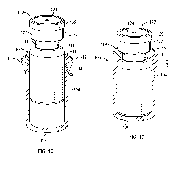
[00102] In Figures 1A-1E, the sleeve 100 includes a cylindrical body 104,
which may include
a cylindrical inner surface configured to receive a lower portion 116 of the
vial 102. In some
embodiments, the body 104 may include a cylindrical outer surface. In some
embodiments, the
14
CA 03018426 2018-09-19
WO 2017/197222 PCT/US2017/032336
upper edge 108 of the body 104 may define an opening of the sleeve 100 into
which the vial 102
may be inserted. The body 104 includes a longitudinal axis, a first end, and a
second end 126. A
deformable member 106 is disposed near the first end of the body 104 and is
arranged to deform
from a first configuration, as illustrated in Figures 1A and 1B, to a second
configuration shown
in Figure 1C. The deformable member 106 is displaced outwardly relative to the
longitudinal
axis of the body 104 in the second configuration. In this embodiment, the
sleeve 100 includes a
plurality of fingers 106 extending upwardly from an upper edge 108 of the
first end of the body
104. In another embodiment, the sleeve 100 may include only one extending
deformable
member 106 or finger.
[00103] Figures 1A and 1B illustrate the multiple fingers 106 in the first
position or
configuration, where the fingers 106 are in an unbiased configuration. The
sleeve 100 may
include any number of fingers 106, for example seven fingers 106, as
illustrated in Figures 1A
and 1B. Each of the plurality of deformable members 106 includes a finger, a
tip, and a bent
knuckle portion 112 connecting the finger and the tip. The bent knuckle
portion 112 includes a
bend angle a of, for example, less than 90 degrees. The acute angle a of the
bent knuckle portion
112 may facilitate securement of the vial 102 within the sleeve 100. The
multiple fingers 106 are
spaced apart from each other. Prior to insertion of the vial 102 into the
sleeve 100, each of the
multiple fingers 106 is disposed or occupies the first position or
configuration.
[00104] Referring now to Figure 1C, in response to the vial 102 being
partially inserted into
the body 104, each of the multiple fingers 106 may be biased outwardly to the
second position or
configuration. In response to the vial 102 being fully inserted into the body
104 in Figure 1D,
each of the plurality of fingers 106 is configured to resiliently return
toward the first position,
contacting a shoulder 114 of the vial 102 and trapping the vial 102 within the
body 104 of the
sleeve 100.
[00105] The vial 102 may have various shapes. Referring to Figures 1C and 1D,
the vial 102
includes a lower portion 116, a shoulder 114, a neck 118, and a top portion
120, which may be
outwardly protruding relative to the neck 118. The top portion 120 may be
sealed with a cap
122, which may include and/or at least partially cover a septum 124. In some
embodiments, a
CA 03018426 2018-09-19
WO 2017/197222 PCT/US2017/032336
bottom 126 of the sleeve 100 may be closed such that the vial 102 may not exit
the bottom 126
and a circumference of the lower portion 116 may be constant.
[00106] In some embodiments the cap 122 may include a first layer 127, which
may be
constructed of one or more materials, such as, for example, aluminum. The
first layer 127 may
be configured to secure the septum 124 to the vial 102 and/or may include an
aluminum crimp
sleeve. When the cap 122 is in place, the first layer 127 may cover all or a
portion of the septum
124. The cap 122 includes a second layer 129, which may be constructed of one
or more
materials, such as, for example, plastic. The second layer 129 may be fitted
over the first layer
127, such that tearing away the second layer 129 from the first layer 127 may
remove a central
portion of the first layer 127, exposing the septum 124 and allowing insertion
of a needle to
pierce the septum 124. In some embodiments, the cap 122 may include any number
of
configurations.
[00107] Referring now to Figure 1E, a closed system transfer device ("CSTD")
130 may be
coupled with the vial 102. One or more hooks of the CSTD 130 may engage with
an outwardly
extending bottom surface 206 of a top portion 120 of the vial 102 and/or the
cap 122, such as, for
example, the first layer 127 of the cap 122. The multiple fingers 106 may
share the shoulder 114
and/or neck 118 of the vial 102 with one or more arms 132 of the CSTD 130.
[00108] A second example vial and sleeve assembly is illustrated in Figures 2A-
2Cand
includes a sleeve 200 that may be or correspond to the sleeve 100. The sleeve
200 includes inner
and outer surfaces that form a wall 202. The sleeve 200 includes a plurality
of deformable
members 204 or multiple indents 204 that are disposed in the wall 202. Each of
the multiple
indents 204 is formed by a portion of the wall 202 pushed inwardly towards a
longitudinal axis
or center of the sleeve 200. Each of the multiple indents 204 is spaced apart
from the wall 202
along a length of the corresponding indent 204. In further detail, an upper
edge and a lower edge
of each of the multiple indents 204 is spaced apart from the wall 202 along a
length of each of
the upper edge and the lower edge, as illustrated, for example, in Figure 2B.
Figure 2C
illustrates the vial 102 partially inserted into the sleeve 200, the bottom
portion 116 of the vial
pushing the indents 204 outwardly and away from the longitudinal axis of the
sleeve 200 to
occupy the second configuration.
16
CA 03018426 2018-09-19
WO 2017/197222 PCT/US2017/032336
[00109] The multiple indents 204 are configured to align with the neck 118 of
the vial 102,
contacting the shoulder 114 and/or a bottom surface 206 of the top portion 120
of the vial 102
and trapping the vial 102 within the sleeve 200, as illustrated, for example,
in Figure 2C. In
Figure 2C, the vial is fully inserted into the sleeve 200 and the multiple
indents proximate to the
top portion of the sleeve 200 are in the first configuration. Each of the
multiple indents 204
includes a width 208 corresponding to a width of the neck 118 of the vial 102,
which is disposed
between the shoulder 114 and the top portion 120 of the vial 102.
[00110] In a preferred embodiment, the vial 102 may be inserted into the
sleeve 200 prior to
formation of the multiple indents 204. Once the vial 102 is fully inserted
into the sleeve 200, as
illustrated in Figure 2C, the multiple indents 204 may be deformed inwardly
(or return to the first
configuration) to engage the neck 118 and secure the vial 102 within the
sleeve 200. For
example, the multiple indents 204 may be laser-cut to deform inwardly.
[00111] One or more indents 204 may be disposed at least proximate a bottom
portion 116 of
the vial 102, which may facilitate indexing of the sleeve 200 to correctly
orient a crimping tool.
The indents 204 disposed at the bottom or lower portion 116 of the sleeve 200
may support the
vial 102 and keep the vial 102 from falling through the open end 226 of the
sleeve 200.
[00112] Referring now to Figures 3A-3D, a system for securing the vial 102
include a vial and
sleeve assembly including a sleeve 300 and a compressible element 302. The
sleeve 300 may
include or correspond to the sleeve 100 of Figure 1 and/or the sleeve 200 of
Figure 2. The
compressible element 302 is configured to be secured or placed around the neck
118 of the vial
102. In some embodiments, the compressible element 302 may be configured in a
shape of a
ring or in a shape of a partial ring. The compressible element 302 includes a
first end 304 and a
second end 306. In the illustrated embodiment, the third vial and sleeve
assembly secures the vial
102 to the sleeve 300 with the help of the compressible element 302. In other
embodiments, the
sleeve 300 may secure to the vial 102 without requiring the compressible
element 302.
[00113] The sleeve 300 may include one or more apertures 308 to allow a health
care
professional to view the contents in the vial 102. In some embodiments, the
sleeve 300 may be
17
CA 03018426 2018-09-19
WO 2017/197222 PCT/US2017/032336
configured such that the contents of the vial 102 may be viewed from a top
and/or a bottom of
the vial 102.
[00114] The compressible element 302 includes a flange 310 that extends
outwardly from an
outer side surface of the compressible element 302 in a horizontal plane. The
compressible
element 302 is configured to compress to fit inside an upper portion of the
sleeve 300, as
illustrated, for example, in Figure 3B, and to decompress in response to the
flange 310 aligning
with a groove 312 disposed in an inner surface of the sleeve 300, as
illustrated, for example, in
Figure 3D. The groove 312 extends around at least a portion of an inner
circumference of the
sleeve 300. The flange 310 is configured to contact an upper portion of the
groove 312 when the
flange 310 is aligned with the groove 312, which may prevent the compressible
element 302 and
the vial 102 from being removed upwardly through an opening of the sleeve 300.
[00115] An upper surface 314 of the compressible element 302 is disposed in
another
horizontal plane. The compressible element 302 includes a lower surface 316
opposite the upper
surface 314 and disposed at an angle with respect to the upper surface 314.
The lower surface
316 may be configured to contact the shoulder 114 of the vial 102 when the
flange 310 is aligned
with the groove 312, and the upper surface 314 may be configured to contact
the bottom surface
206 of the top portion 120 of the vial 102 when the flange 310 is aligned with
the groove 312.
[00116] An outer surface of the sleeve 300 includes an outer flange 318
extending around at
least a portion of an outer circumference of the sleeve 300. The outer flange
318 extends to a
first end of the sleeve 300 and includes an aperture 319 (illustrated in
Figures 3A-3C) to
facilitate removal of the cap 122 of the vial 102.
[00117] Referring now to Figures 3E and 3F, the outer flange 318 is configured
to engage
with a device or adapter, such as, for example, a closed system transfer
device ("CSTD") 320.
The CSTD 320 includes a plurality of arms or hooks 321, which couples to a
bottom surface of
the outer flange 318, as illustrated, for example, in Figure 3F. Coupling may
include a friction or
interference fit. The compressible element 302 attached to the neck 118 of the
vial 102 may not
permit attachment of the CSTD 320 to the vial 102. So configured, the outer
flange 310 provides
an alternate coupling location for coupling with the CSTD 320. A needle 323 of
the CSTD 320
18
CA 03018426 2018-09-19
WO 2017/197222 PCT/US2017/032336
may pierce the septum 124 to allow access to the contents of the vial 102, as
illustrated, for
example, in Figure 3F. In some embodiments, a size of the outer flange 318 may
be one standard
size larger than a size of the cap 122. Thus, in some embodiments, a size of
the CSTD 320 may
correspond to the size of the outer flange 318. For example, the CSTD 320 may
be sized and
configured to be used in a particular system with a 20 mm cap 122 and a 15 mm
diameter cap
122.
[00118] As illustrated in Figure 3A-3D, in some embodiments, the sleeve 300
may extend
along all or almost all of a length of the vial 102. In Figure 3G, the sleeve
300 extends along a
portion of the length of the vial 102. A bottom end 326 of the sleeve 300 may
be partially closed
to engage the vial 102 when the vial 102 is fully inserted into the sleeve
300. In a different
sleeve 300 illustrated in Figure 3H, a bottom 328 of the sleeve 300 may be
open. Additionally,
the sleeve in Figure 3H includes a variation of the compressible element 302
in the previous
figures, and includes a first flange 322 and a second flange 324 which extend
parallel to each
other, each in a horizontal plane. The first and second flanges 322, 324 may
prevent the
compressible element 302 and the vial 102 from moving upward and downward,
respectively. In
some embodiments, the sleeve 300 may include a tapered entry 327, which may
facilitate
compression of the ring during insertion.
[00119] Referring now to a fourth example vial and sleeve assembly in Figures
4A-4D, a
sleeve 400 includes an enlarged outer flange 402 extending from a top portion
of the sleeve 400.
The sleeve 400 may include or correspond to one or more of the following: the
sleeve 100 of
Figure 1, the sleeve 200 of Figure 2, and the sleeve 300 of Figure 3. As an
example, one or more
apertures 404 may include or correspond to the apertures 308 of Figure 3
and/or the outer flange
402 may include or correspond to the outer flange 316 of Figure 3.
[00120] As shown in Figures 4B and 4C, the sleeve 400 includes a plurality of
deformable
members 406 or fingers 406 spaced apart and extending downwardly from the
inner surface of
the sleeve 400 near the top portion of the sleeve 400. In the illustrated
example, the second end
426 of the sleeve 400 is partially open, forming a ledge configured to hold
the vial 102 in place.
Prior to insertion of the vial 102 into the sleeve 400, each of the multiple
fingers 406 is disposed
in a first position or configuration, illustrated, for example, in Figure 4C.
In response to the vial
19
CA 03018426 2018-09-19
WO 2017/197222 PCT/US2017/032336
102 being partially inserted into the sleeve 400, each of the multiple fingers
406 is biased
outwardly relative to the longitudinal axis and toward the inner surface of
the sleeve 400, as
shown in Figure 4D. When the deformable members 406 deform from the first
configuration to
a second position or configuration, the tip of each finger 406 flexes
outwardly relative to the
longitudinal axis of the sleeve 400 and pivots at the bent knuckle portion of
the deformable
member 406 (i.e. where the flange 402 attaches to the top portion of the
sleeve 400). As
illustrated, for example, in Figure 4B, in response to the vial 102 being
fully inserted into the
sleeve 400, the tip of each finger 406 pivots about the bent knuckle portion
to resiliently move
back toward the first configuration and engage the shoulder 114 of the vial
102, thereby and
trapping the vial 102 within the sleeve 400.
[00121] In Figure 4E, the outer flange 402 is configured to engage with a
device or adapter,
such as, for example, a CSTD 408, which may include or correspond to the CSTD
320 in some
embodiments. A size of the outer flange 402 may be selected based on a size of
a corresponding
receiving portion for the outer flange 402. The receiving portion may be
disposed in a lower
surface of the CSTD 320.
[00122] Referring now to a fifth vial and sleeve assembly in Figures 5A-5F, a
system may
include a sleeve 500 and a compressible element 502. The sleeve 500 may
include or correspond
to one or more of the following: the sleeve 100 of Figure 1, the sleeve 200 of
Figure 2, the sleeve
300 of Figure 3, and the sleeve 400 of Figure 4. In some embodiments, the
compressible element
502 may include or correspond to the compressible element 302, and the sleeve
500 may secure
to the vial 102 with or without the compressible element 502.
[00123] The compressible element 502 includes a first end 504 having a first
protrusion 506,
and a second end 508 having a second protrusion 510. A wall 512 of the sleeve
500 is defined by
the inner and outer surfaces of the sleeve 500 and includes a slot 516 sized
to receive the
compressible element 502. The slot 516 is aligned with the neck 118 of the
vial 102 such that
the compressible element 502 is secured around the neck 118 of the vial
through the slot 516, as
illustrated in Figure 5C. The vial 102 may be easily inserted into the sleeve
500 without exerting
a large downward force, and secured via insertion of the compressible member
502 fully in the
slot 516. The vial 102 and the compressible element 502 may be partially
and/or fully inserted
CA 03018426 2018-09-19
WO 2017/197222 PCT/US2017/032336
into the sleeve 500 by exerting a downward force on the vial 102 and
compressible element 502.
The compressible element 502 may be partially and/or fully inserted into the
sleeve 500 by
exerting a lateral force on the compressible element 502 when the compressible
element 502 is
inserted into the slot 516 disposed in the sleeve 500.
[00124] Prior to insertion of the compressible element 502 into the slot 516,
the first and
second ends 504, 508 may be disposed in a first position or configuration,
illustrated, for
example, in Figure 5B. In response to the compressible element 502 being
partially inserted into
the slot 516, the inner surface of the sleeve 500 is configured to press the
first and second ends
504, 508 inwardly into a second position or configuration, as illustrated, for
example, in Figure
5F. In response to the compressible element 502 being fully inserted into the
slot 516 and the
first and second protrusions 506, 510 aligning with first and second grooves
515, 517 disposed in
the inner surface of the sleeve 500, respectively, the first and second ends
504, 508 are
configured to resiliently move toward the first position, trapping the first
and second protrusions
506, 510 in the first and second grooves 515, 517, respectively, and the vial
102 within the
sleeve 500. The first and second grooves 515, 517 are illustrated, for
example, in Figure 5E,
which is a cross-sectional view along line 1-1 of Figure 5A. The compressible
element 502
includes first and second extensions 519, 520 spaced apart from the first and
second ends 504,
508 to support and facilitate the first and second ends 504, 508 when
deforming from the first
configuration to the second configuration.
[00125] The sleeve 500 includes an outer flange 518 for coupling with a CSTD,
such as, for
example, CSTD 320 and/or CSTD 408. A bottom of the sleeve 500 is open, as
illustrated, for
example, in Figure 5C, and in another embodiment, the bottom of the sleeve 500
may be closed.
As best shown in Figures 5D and 5E, the first and second protrusions 506, 510
are configured to
fit within the first and second grooves 515, 517 to prevent the vial 102 from
moving upwards or
downwards with respect to the sleeve 500. In the embodiment illustrated in
Figures 5D and 5E,
the sleeve 500 includes one or more pin holes 522 which is configured to align
with the first end
504 and/or the second end 508 of the compressible element 502. The pin holes
522 may allow
insertion of a pin or similar object to press the first end 504 and/or the
second end 508 inwardly
and remove the compressible element 502 from the sleeve 500, allowing the vial
102 to be
21
CA 03018426 2018-09-19
WO 2017/197222 PCT/US2017/032336
removed from the sleeve 500 for any number of purposes, such as, for example,
direct
conductive thermal contact of an exterior surface of the vial 102 with a
thawing tool.
[00126] In some embodiments, a particular sleeve may be a unitary piece.
Referring now to
Figures 6A-6F, in some embodiments, a sleeve 600 may include an upper piece
602 and a lower
piece 604, which may be coupled together. In some embodiments, the sleeve 600
may include or
correspond to one or more of the following: the sleeve 100 of Figure 1, the
sleeve 200 of Figure
2, the sleeve 300 of Figure 3, the sleeve 400 of Figure 4, and the sleeve 500
of Figure 5. In some
embodiments, the upper piece 602 and the lower piece 604 may be coupled
together via a first
means and/or an adhesive sticker 606. The first means may include an
interference fit, friction
fit, threading, or another means of coupling. In some embodiments, the upper
piece 602 and the
lower piece 604 may include one or more projections and/or corresponding
receiving portions
that may interact with each other in order to couple the upper piece 602 and
the lower piece 604.
In some embodiments, the system may include a filament 608, which may be
disposed in a gap
610 between the upper piece 602 and the lower piece 604. In some embodiments,
the gap 610
may extend around all or a portion of an outer circumference of the upper
piece 602, the lower
piece 604, and/or between the upper and lower pieces 602, 604.
[00127] In some embodiments, the system may include the sticker 606 adhered to
an outer
surface of the upper piece 602 and the lower piece 604 and covering at least a
portion of the gap
610. In some embodiments, the sticker 606 may extend around all or a portion
of an outer
circumference of the sleeve 600. In some embodiments, an end of the filament
608 is configured
to be pulled by a user in order to tear through the sticker 606 and uncouple
the upper piece 602
and the lower piece 604. In some embodiments, the end of the filament 608 may
be disposed
within a tab 612, which may aid in pulling the filament 608.
[00128] Figure 6C illustrates the sticker 606 and filament 608 removed and the
upper and
lower pieces 602, 604 separated. Figure 6E illustrates a foot extension 614
coupled to the lower
piece 604 of the sleeve 600, which may have an outer circumference equal to an
outer
circumference of an outer flange 616 in order to facilitate use with
machinery, such as, for
example, automated loading machinery, automated thawing machinery, etc. Figure
6F illustrates
the outer flange 616 coupled with a device or adapter, such as, for example, a
CSTD 618, which
22
CA 03018426 2018-09-19
WO 2017/197222 PCT/US2017/032336
may include or correspond to the CSTD 320 and/or CSTD 408 in some embodiments.
In some
embodiments, the lower piece 604 may be removed while the upper piece 604 is
coupled with
the CSTD 618. Thus, thawing may occur while the vial 102 is still coupled with
the CSTD 618.
[00129] Referring now to a seventh vial and sleeve assembly in Figures 7A-7E,
a system for
securing the vial 102 includes a compressible element 700 and a sleeve 702. In
some
embodiments, the compressible element 700 includes or corresponds to the
compressible element
302 of Figures 3A-3H, and the sleeve 702 includes or corresponds to one or
more of the
following: the sleeve 100, the sleeve 200, the sleeve 300, the sleeve 400, the
sleeve 500, and the
sleeve 600 of the previous figures.
[00130] A shown in Figure 7B, the compressible element 700 is configured to be
secured or
placed around at least a portion of the shoulder 114 of the vial 102. The
compressible element
700 is in a shape of a partial ring and is configured to extend approximately
300 degrees around
the vial 102. In some embodiments, the compressible element 700 may be low-
profile such that
the compressible element 700 does not interfere with and/or contact one or
more arms 704 and/or
hooks 706 disposed on the arms 704 of a CSTD 708, which may occupy at least a
portion of the
neck 118 of the vial 102. As shown in Figure 7C, the hooks 706 may engage with
the outwardly
extending bottom surface of the top portion of the vial 102 and/or the cap
122.
[00131] In Figure 7B, the compressible element 700 includes a concave flange
portion 710
shaped to correspond to a shape of the shoulder 114 of the vial 102. When the
vial 102 and the
compressible element 700 are fully inserted within the sleeve 702 as shown in
Figures 7C and
7E, the flange portion 710 extends around a portion of the shoulder 114 of the
vial 102 and may
contact the portion of the shoulder 114. In these and other embodiments, the
flange portion 710
may contact the shoulder 114 to prevent compression or further compression of
the compressible
element 700. The compressible element 700 includes a ledge 712, which
protrudes outwardly
from the flange portion 710. When the compressible element 700 is fully
inserted within the
sleeve 702, as illustrated in Figure 7E, the ledge 712 contacts an upper edge
713 of the sleeve
702, which may prevent downward movement of the compressible element 700.
23
CA 03018426 2018-09-19
WO 2017/197222 PCT/US2017/032336
[0100] An extension 714 extends downwardly from the ledge 712, and may extend
around all
or a portion of the lower portion 116 and/or the shoulder 114 of the vial 102.
The compressible
element 700 may include multiple extensions, and the extension 714 includes a
coupling
element, which facilitates coupling of the compressible element 700 with an
inner surface of the
sleeve 702. For example, the extension includes a protrusion 716, which is
received into a
receiving portion or groove 718 disposed on the inner surface of the sleeve
702. The extension
714 may be flexible, and is configured to move between a first position or
configuration and a
second position or configuration. When the vial 102 is fully inserted in the
sleeve 102 and the
compressible element 700 is partially inserted in the sleeve 102, as
illustrated in Figure 7D, the
extension 714 is disposed inwardly in the first position. When the extension
714 is disposed in
the first position, the protrusion 716 may be offset from the groove 718
and/or contact between
the protrusion 716 and the inner surface of the sleeve 102 may bias the
extension 714 in the first
position.
[0101] When the vial 102 is fully inserted in the sleeve 102 and the
compressible element 700
is fully inserted in the sleeve 702, as illustrated in Figure 7E, the
extension 714 is disposed in a
second position. When the compressible element 700 is fully inserted in the
sleeve 702, a bottom
edge 719 of the extension 714 may contact a flange 720 of the inner surface of
the sleeve 702,
which may prevent downward movement of the compressible element 700. When the
protrusion
716 is aligned with the groove 718, the extension 714 may resiliently return
to the second
position after being in the first position.
[0102] In some embodiments, an insertion tool or machine may be used to push
the sleeve
over the vial at room temperature or low temperature, such as, for example,
negative 80 degrees
C. In some embodiments, the sleeve may be constructed of plastic, metal, a
polymer, and/or
another suitable material. In some embodiments, the metal may include
aluminum. In some
embodiments, a material of the sleeve may be sustainable at low temperature to
allow the sleeve
to function at low temperature. In some embodiments, the sleeve may include a
single unitary
piece. In other embodiments, the sleeve may include multiple pieces, which may
be coupled
together. In some embodiments, a tool may be required to secure the vial
within the sleeve by
engagement of a secondary sleeve part and/or a crimping process.
24
CA 03018426 2018-09-19
WO 2017/197222 PCT/US2017/032336
[0103] In some embodiments, the outer flange may be configured to engage with
a device,
such as, for example, a closed system transfer device ("CSTD"). Various types
of CSTDs may be
coupled with the sleeve. The CSTD may be used for safe transfer of potentially
hazardous
contents of the vial and/or may prevent needle sticks. The CSTD may provide a
means to make
transfers between vials, syringes, and IV bags without exposing the health
care professional to
the contents. An example of a CSTD may include the PHASEALTM CSTD commercially
available from Becton, Dickinson, and Company.
[0104] In some embodiments, the sleeve may be used to label the vial. For
example, the sleeve
may include a particular color, marking, or other indicator of the contents of
the vial. In some
embodiments, the color, marking, or other indicator may identify the contents
of the vial to an
administrator of a blind study but not to a health care professional
administering the contents of
the vial or a patient receiving the contents of the vial. In some embodiments,
the sleeve may hide
the contents of the vial and/or a previously applied label on the vial, such
as, for example, an
adhesive label.
[0105] In some embodiments, the health care professional and/or the patient
may not be able
to remove the vial from the sleeve without evidence of tampering. Thus, in
some embodiments,
the contents of the vial and/or the label on the vial may not be viewed
without evidence of
tampering. In some instances, a placebo and experimental drug look the same or
similar. In these
and other embodiments, the sleeve may include one or more apertures that may
allow the health
care professional to view an amount of the contents present in the vial. In
some embodiments,
the sleeve may be configured such that the contents of the vial may be viewed
from a top and/or
a bottom of the vial.
[0106] The present invention may be embodied in other specific forms without
departing from
its structures, methods, or other essential characteristics as broadly
described herein and claimed
hereinafter. The described embodiments are to be considered in all respects
only as illustrative,
and not restrictive. The scope of the invention is, therefore, indicated by
the appended claims,
rather than by the foregoing description. All changes that come within the
meaning and range of
equivalency of the claims are to be embraced within their scope.
CA 03018426 2018-09-19
WO 2017/197222 PCT/US2017/032336
[0107] The above description describes various systems and methods for use
with vial sleeve.
It should be clear that the system, vial sleeve or methods can further
comprise use of a
medicament listed below with the caveat that the following list should neither
be considered to
be all inclusive nor limiting.
[0108] For example, the vial may be filled with colony stimulating factors,
such as
granulocyte colony-stimulating factor (G-CSF). Such G-CSF agents include, but
are not limited
to, Neupogen (filgrastim) and Neulasta (pegfilgrastim). In various other
embodiments, the
drug delivery device may be used with various pharmaceutical products, such as
an
erythropoiesis stimulating agent (ESA), which may be in a liquid or a
lyophilized form. An ESA
is any molecule that stimulates erythropoiesis, such as Epogen (epoetin
alfa), Aranesp
(darbepoetin alfa), Dynepo (epoetin delta), Mircera (methyoxy polyethylene
glycol-epoetin
beta), Hematide , MRK-2578, INS-22, Retacrit (epoetin zeta), Neorecormon
(epoetin beta),
Silapo (epoetin zeta), Binocrit (epoetin alfa), epoetin alfa Hexal, Abseamed
(epoetin alfa),
Ratioepo (epoetin theta), Eporatio (epoetin theta), Biopoin (epoetin
theta), epoetin alfa,
epoetin beta, epoetin zeta, epoetin theta, and epoetin delta, as well as the
molecules or variants or
analogs thereof as disclosed in the following patents or patent applications,
each of which is
herein incorporated by reference in its entirety: U.S. Patent Nos. 4,703,008;
5,441,868;
5,547,933; 5,618,698; 5,621,080; 5,756,349; 5,767,078; 5,773,569; 5,955,422;
5,986,047;
6,583,272; 7,084,245; and 7,271,689; and PCT Publication Nos. WO 91/05867; WO
95/05465;
WO 96/40772; WO 00/24893; WO 01/81405; and WO 2007/136752.
[0109] An ESA can be an erythropoiesis stimulating protein. As used herein,
"erythropoiesis
stimulating protein" means any protein that directly or indirectly causes
activation of the
erythropoietin receptor, for example, by binding to and causing dimerization
of the receptor.
Erythropoiesis stimulating proteins include erythropoietin and variants,
analogs, or derivatives
thereof that bind to and activate erythropoietin receptor; antibodies that
bind to erythropoietin
receptor and activate the receptor; or peptides that bind to and activate
erythropoietin receptor.
Erythropoiesis stimulating proteins include, but are not limited to, epoetin
alfa, epoetin beta,
epoetin delta, epoetin omega, epoetin iota, epoetin zeta, and analogs thereof,
pegylated
erythropoietin, carbamylated erythropoietin, mimetic peptides (including
EMPl/hematide), and
26
CA 03018426 2018-09-19
WO 2017/197222 PCT/US2017/032336
mimetic antibodies. Exemplary erythropoiesis stimulating proteins include
erythropoietin,
darbepoetin, erythropoietin agonist variants, and peptides or antibodies that
bind and activate
erythropoietin receptor (and include compounds reported in U.S. Publication
Nos. 2003/0215444
and 2006/0040858, the disclosures of each of which is incorporated herein by
reference in its
entirety) as well as erythropoietin molecules or variants or analogs thereof
as disclosed in the
following patents or patent applications, which are each herein incorporated
by reference in its
entirety: U.S. Patent Nos. 4,703,008; 5,441,868; 5,547,933; 5,618,698;
5,621,080; 5,756,349;
5,767,078; 5,773,569; 5,955,422; 5,830,851; 5,856,298; 5,986,047; 6,030,086;
6,310,078;
6,391,633; 6,583,272; 6,586,398; 6,900,292; 6,750,369; 7,030,226; 7,084,245;
and 7,217,689;
U.S. Publication Nos. 2002/0155998; 2003/0077753; 2003/0082749; 2003/0143202;
2004/0009902; 2004/0071694; 2004/0091961; 2004/0143857; 2004/0157293;
2004/0175379;
2004/0175824; 2004/0229318; 2004/0248815; 2004/0266690; 2005/0019914;
2005/0026834;
2005/0096461; 2005/0107297; 2005/0107591; 2005/0124045; 2005/0124564;
2005/0137329;
2005/0142642; 2005/0143292; 2005/0153879; 2005/0158822; 2005/0158832;
2005/0170457;
2005/0181359; 2005/0181482; 2005/0192211; 2005/0202538; 2005/0227289;
2005/0244409;
2006/0088906; and 2006/0111279; and PCT Publication Nos. WO 91/05867; WO
95/05465;
WO 99/66054; WO 00/24893; WO 01/81405; WO 00/61637; WO 01/36489; WO 02/014356;
WO 02/19963; WO 02/20034; WO 02/49673; WO 02/085940; WO 03/029291; WO
2003/055526; WO 2003/084477; WO 2003/094858; WO 2004/002417; WO 2004/002424;
WO
2004/009627; WO 2004/024761; WO 2004/033651; WO 2004/035603; WO 2004/043382;
WO
2004/101600; WO 2004/101606; WO 2004/101611; WO 2004/106373; WO 2004/018667;
WO
2005/001025; WO 2005/001136; WO 2005/021579; WO 2005/025606; WO 2005/032460;
WO
2005/051327; WO 2005/063808; WO 2005/063809; WO 2005/070451; WO 2005/081687;
WO
2005/084711; WO 2005/103076; WO 2005/100403; WO 2005/092369; WO 2006/50959; WO
2006/02646; and WO 2006/29094.
[0110] Examples of other pharmaceutical products for use with the device may
include, but
are not limited to, antibodies such as Vectibix (panitumumab), XgevaTM
(denosumab) and
ProliaTM (denosamab); other biological agents such as Enbrel (etanercept, TNF-
receptor /Fc
fusion protein, TNF blocker), Neulasta (pegfilgrastim, pegylated filgastrim,
pegylated G-CSF,
27
CA 03018426 2018-09-19
WO 2017/197222 PCT/US2017/032336
pegylated hu-Met-G-CSF), Neupogen (filgrastim , G-CSF, hu-MetG-CSF), and
Nplate
(romiplostim); small molecule drugs such as Sensipar (cinacalcet). The device
may also be
used with a therapeutic antibody, a polypeptide, a protein or other chemical,
such as an iron, for
example, ferumoxytol, iron dextrans, ferric glyconate, and iron sucrose. The
pharmaceutical
product may be in liquid form, or reconstituted from lyophilized form.
[0111] Among particular illustrative proteins are the specific proteins set
forth below,
including fusions, fragments, analogs, variants or derivatives thereof:
[0112] OPGL specific antibodies, peptibodies, and related proteins, and the
like (also referred
to as RANKL specific antibodies, peptibodies and the like), including fully
humanized and
human OPGL specific antibodies, particularly fully humanized monoclonal
antibodies, including
but not limited to the antibodies described in PCT Publication No. WO
03/002713, which is
incorporated herein in its entirety as to OPGL specific antibodies and
antibody related proteins,
particularly those having the sequences set forth therein, particularly, but
not limited to, those
denoted therein: 9H7; 18B2; 2D8; 2E11; 16E1; and 22B3, including the OPGL
specific
antibodies having either the light chain of SEQ ID NO:2 as set forth therein
in Figure 2 and/or
the heavy chain of SEQ ID NO:4, as set forth therein in Figure 4, each of
which is individually
and specifically incorporated by reference herein in its entirety fully as
disclosed in the foregoing
publication;
[0113] Myostatin binding proteins, peptibodies, and related proteins, and the
like, including
myostatin specific peptibodies, particularly those described in U.S.
Publication No.
2004/0181033 and PCT Publication No. WO 2004/058988, which are incorporated by
reference
herein in their entirety particularly in parts pertinent to myostatin specific
peptibodies, including
but not limited to peptibodies of the mTN8-19 family, including those of SEQ
ID NOS:305-351,
including TN8-19-1 through TN8-19-40, TN8-19 conl and TN8-19 con2; peptibodies
of the
mL2 family of SEQ ID NOS:357-383; the mL15 family of SEQ ID NOS:384-409; the
mL17
family of SEQ ID NOS:410-438; the mL20 family of SEQ ID NOS:439-446; the mL21
family of
SEQ ID NOS:447-452; the mL24 family of SEQ ID NOS:453-454; and those of SEQ ID
NOS:615-631, each of which is individually and specifically incorporated by
reference herein in
their entirety fully as disclosed in the foregoing publication;
28
CA 03018426 2018-09-19
WO 2017/197222 PCT/US2017/032336
[0114] IL-4 receptor specific antibodies, peptibodies, and related proteins,
and the like,
particularly those that inhibit activities mediated by binding of IL-4 and/or
IL-13 to the receptor,
including those described in PCT Publication No. WO 2005/047331 or PCT
Application No.
PCT/US2004/37242 and in U.S. Publication No. 2005/112694, which are
incorporated herein by
reference in their entirety particularly in parts pertinent to IL-4 receptor
specific antibodies,
particularly such antibodies as are described therein, particularly, and
without limitation, those
designated therein: L1H1; L1H2; L1H3; L1H4; L1H5; L1H6; L1H7; L1H8; L1H9;
L1H10;
L1H11; L2H1; L2H2; L2H3; L2H4; L2H5; L2H6; L2H7; L2H8; L2H9; L2H10; L2H11;
L2H12;
L2H13; L2H14; L3H1; L4H1; L5H1; L6H1, each of which is individually and
specifically
incorporated by reference herein in its entirety fully as disclosed in the
foregoing publication;
[0115] Interleukin 1-receptor 1 ("ILl-R 1") specific antibodies, peptibodies,
and related
proteins, and the like, including but not limited to those described in U.S.
Publication No.
2004/097712, which is incorporated herein by reference in its entirety in
parts pertinent to IL1-
R1 specific binding proteins, monoclonal antibodies in particular, especially,
without limitation,
those designated therein: 15CA, 26F5, 27F2, 24E12, and 10H7, each of which is
individually
and specifically incorporated by reference herein in its entirety fully as
disclosed in the
aforementioned publication;
[0116] Ang2 specific antibodies, peptibodies, and related proteins, and the
like, including but
not limited to those described in PCT Publication No. WO 03/057134 and U.S.
Publication No.
2003/0229023, each of which is incorporated herein by reference in its
entirety particularly in
parts pertinent to Ang2 specific antibodies and peptibodies and the like,
especially those of
sequences described therein and including but not limited to: Ll(N); L1(N) WT;
L1(N) 1K WT;
2xL1(N); 2xL1(N) WT; Con4 (N), Con4 (N) 1K WT, 2xCon4 (N) 1K; L1C; L1C 1K;
2xL1C;
Con4C; Con4C 1K; 2xCon4C 1K; Con4-L1 (N); Con4-L1C; TN-12-9 (N); C17 (N); TN8-
8(N);
TN8-14 (N); Con 1 (N), also including anti-Ang 2 antibodies and formulations
such as those
described in PCT Publication No. WO 2003/030833 which is incorporated herein
by reference in
its entirety as to the same, particularly Ab526; Ab528; Ab531; Ab533; Ab535;
Ab536; Ab537;
Ab540; Ab543; Ab544; Ab545; Ab546; A551; Ab553; Ab555; Ab558; Ab559; Ab565;
AbFlAbFD; AbFE; AbFJ; AbFK; AbG1D4; AbGC1E8; AbH1C12; AblAl; AblF; AblK, AblP;
29
CA 03018426 2018-09-19
WO 2017/197222 PCT/US2017/032336
and AblP, in their various permutations as described therein, each of which is
individually and
specifically incorporated by reference herein in its entirety fully as
disclosed in the foregoing
publication;
[0117] NGF specific antibodies, peptibodies, and related proteins, and the
like including, in
particular, but not limited to those described in U.S. Publication No.
2005/0074821 and U.S.
Patent No. 6,919,426, which are incorporated herein by reference in their
entirety particularly as
to NGF-specific antibodies and related proteins in this regard, including in
particular, but not
limited to, the NGF-specific antibodies therein designated 4D4, 4G6, 6H9, 7H2,
14D10 and
14D11, each of which is individually and specifically incorporated by
reference herein in its
entirety fully as disclosed in the foregoing publication;
[0118] CD22 specific antibodies, peptibodies, and related proteins, and the
like, such as those
described in U.S. Patent No. 5,789,554, which is incorporated herein by
reference in its entirety
as to CD22 specific antibodies and related proteins, particularly human CD22
specific
antibodies, such as but not limited to humanized and fully human antibodies,
including but not
limited to humanized and fully human monoclonal antibodies, particularly
including but not
limited to human CD22 specific IgG antibodies, such as, for instance, a dimer
of a human-mouse
monoclonal hLL2 gamma-chain disulfide linked to a human-mouse monoclonal hLL2
kappa-
chain, including, but limited to, for example, the human CD22 specific fully
humanized antibody
in Epratuzumab, CAS registry number 501423-23-0;
[0119] IGF-1 receptor specific antibodies, peptibodies, and related proteins,
and the like, such
as those described in PCT Publication No. WO 06/069202, which is incorporated
herein by
reference in its entirety as to IGF-1 receptor specific antibodies and related
proteins, including
but not limited to the IGF-1 specific antibodies therein designated L1H1,
L2H2, L3H3, L4H4,
L5H5, L6H6, L7H7, L8H8, L9H9, L10H10, L11H11, L12H12, L13H13, L14H14, L15H15,
L16H16, L17H17, L18H18, L19H19, L20H20, L21H21, L22H22, L23H23, L24H24,
L25H25,
L26H26, L27H27, L28H28, L29H29, L30H30, L31H31, L32H32, L33H33, L34H34,
L35H35,
L36H36, L37H37, L38H38, L39H39, L40H40, L41H41, L42H42, L43H43, L44H44,
L45H45,
L46H46, L47H47, L48H48, L49H49, L50H50, L51H51, L52H52, and IGF-1R-binding
CA 03018426 2018-09-19
WO 2017/197222 PCT/US2017/032336
fragments and derivatives thereof, each of which is individually and
specifically incorporated by
reference herein in its entirety fully as disclosed in the foregoing
publication;
[0120] Also among non-limiting examples of anti-IGF-1R antibodies for use in
the methods
and compositions of the present invention are each and all of those described
in:
(i) U.S. Publication No. 2006/0040358 (published February 23, 2006),
2005/0008642
(published January 13, 2005), 2004/0228859 (published November 18, 2004),
including but not
limited to, for instance, antibody lA (DSMZ Deposit No. DSM ACC 2586),
antibody 8 (DSMZ
Deposit No. DSM ACC 2589), antibody 23 (DSMZ Deposit No. DSM ACC 2588) and
antibody
18 as described therein;
(ii) PCT Publication No. WO 06/138729 (published December 28, 2006) and WO
05/016970 (published February 24, 2005), and Lu et al. (2004), J. Biol. Chem.
279:2856-2865,
including but not limited to antibodies 2F8, Al2, and IMC-Al2 as described
therein;
(iii) PCT Publication No. WO 07/012614 (published February 1, 2007), WO
07/000328
(published January 4, 2007), WO 06/013472 (published February 9, 2006), WO
05/058967
(published June 30, 2005), and WO 03/059951 (published July 24, 2003);
(iv) U.S. Publication No. 2005/0084906 (published April 21, 2005), including
but not
limited to antibody 7C10, chimaeric antibody C7C10, antibody h7C10, antibody
7H2M,
chimaeric antibody *7C10, antibody GM 607, humanized antibody 7C10 version 1,
humanized
antibody 7C10 version 2, humanized antibody 7C10 version 3, and antibody
7H2HM, as
described therein;
(v) U.S. Publication Nos. 2005/0249728 (published November 10, 2005),
2005/0186203
(published August 25, 2005), 2004/0265307 (published December 30, 2004), and
2003/0235582
(published December 25, 2003) and Maloney et al. (2003), Cancer Res. 63:5073-
5083, including
but not limited to antibody EM164, resurfaced EM164, humanized EM164, huEM164
v1.0,
huEM164 v1.1, huEM164 v1.2, and huEM164 v1.3 as described therein;
(vi) U.S. Patent No. 7,037,498 (issued May 2, 2006), U.S. Publication Nos.
2005/0244408 (published November 30, 2005) and 2004/0086503 (published May 6,
2004), and
Cohen, et al. (2005), Clinical Cancer Res. 11:2063-2073, e.g., antibody CP-
751,871, including
but not limited to each of the antibodies produced by the hybridomas having
the ATCC
31
CA 03018426 2018-09-19
WO 2017/197222 PCT/US2017/032336
accession numbers PTA-2792, PTA-2788, PTA-2790, PTA-2791, PTA-2789, PTA-2793,
and
antibodies 2.12.1, 2.13.2, 2.14.3, 3.1.1, 4.9.2, and 4.17.3, as described
therein;
(vii) U.S. Publication Nos. 2005/0136063 (published June 23, 2005) and
2004/0018191
(published January 29, 2004), including but not limited to antibody 19D12 and
an antibody
comprising a heavy chain encoded by a polynucleotide in plasmid 15H12/19D12
HCA (y4),
deposited at the ATCC under number PTA-5214, and a light chain encoded by a
polynucleotide
in plasmid 15H12/19D12 LCF (K), deposited at the ATCC under number PTA-5220,
as
described therein; and
(viii) U.S. Publication No. 2004/0202655 (published October 14, 2004),
including but not
limited to antibodies PINT-6A1, PINT-7A2, PINT-7A4, PINT-7A5, PINT-7A6, PINT-
8A1,
PINT-9A2, PINT-11A1, PINT-11A2, PINT-11A3, PINT-11A4, PINT-11A5, PINT-11A7,
PINT-
11Al2, PINT-12A1, PINT-12A2, PINT-12A3, PINT-12A4, and PINT-12A5, as described
therein; each and all of which are herein incorporated by reference in their
entireties, particularly
as to the aforementioned antibodies, peptibodies, and related proteins and the
like that target
IGF-1 receptors;
[0121] B-7 related protein 1 specific antibodies, peptibodies, related
proteins and the like
("B7RP-1," also is referred to in the literature as B7H2, ICOSL, B7h, and
CD275), particularly
B7RP-specific fully human monoclonal IgG2 antibodies, particularly fully human
IgG2
monoclonal antibody that binds an epitope in the first immunoglobulin-like
domain of B7RP-1,
especially those that inhibit the interaction of B7RP-1 with its natural
receptor, ICOS, on
activated T cells in particular, especially, in all of the foregoing regards,
those disclosed in U.S.
Publication No. 2008/0166352 and PCT Publication No. WO 07/011941, which are
incorporated
herein by reference in their entireties as to such antibodies and related
proteins, including but not
limited to antibodies designated therein as follow: 16H (having light chain
variable and heavy
chain variable sequences SEQ ID NO:1 and SEQ ID NO:7 respectively therein); 5D
(having
light chain variable and heavy chain variable sequences SEQ ID NO:2 and SEQ ID
NO:9
respectively therein); 2H (having light chain variable and heavy chain
variable sequences SEQ
ID NO:3 and SEQ ID NO:10 respectively therein); 43H (having light chain
variable and heavy
chain variable sequences SEQ ID NO:6 and SEQ ID NO:14 respectively therein);
41H (having
32
CA 03018426 2018-09-19
WO 2017/197222 PCT/US2017/032336
light chain variable and heavy chain variable sequences SEQ ID NO:5 and SEQ ID
NO:13
respectively therein); and 15H (having light chain variable and heavy chain
variable sequences
SEQ ID NO:4 and SEQ ID NO:12 respectively therein), each of which is
individually and
specifically incorporated by reference herein in its entirety fully as
disclosed in the foregoing
publication;
[0122] IL-15 specific antibodies, peptibodies, and related proteins, and the
like, such as, in
particular, humanized monoclonal antibodies, particularly antibodies such as
those disclosed in
U.S. Publication Nos. 2003/0138421; 2003/023586; and 2004/0071702; and U.S.
Patent No.
7,153,507, each of which is incorporated herein by reference in its entirety
as to IL-15 specific
antibodies and related proteins, including peptibodies, including
particularly, for instance, but
not limited to, HuMax IL-15 antibodies and related proteins, such as, for
instance, 146B7;
[0123] IFN gamma specific antibodies, peptibodies, and related proteins and
the like,
especially human IFN gamma specific antibodies, particularly fully human anti-
IFN gamma
antibodies, such as, for instance, those described in U.S. Publication No.
2005/0004353, which is
incorporated herein by reference in its entirety as to IFN gamma specific
antibodies, particularly,
for example, the antibodies therein designated 1118; 1118*; 1119; 1121; and
1121*. The entire
sequences of the heavy and light chains of each of these antibodies, as well
as the sequences of
their heavy and light chain variable regions and complementarity determining
regions, are each
individually and specifically incorporated by reference herein in its entirety
fully as disclosed in
the foregoing publication and in Thakur et al. (1999), Mol. Immunol. 36:1107-
1115. In addition,
description of the properties of these antibodies provided in the foregoing
publication is also
incorporated by reference herein in its entirety. Specific antibodies include
those having the
heavy chain of SEQ ID NO:17 and the light chain of SEQ ID NO:18; those having
the heavy
chain variable region of SEQ ID NO:6 and the light chain variable region of
SEQ ID NO:8;
those having the heavy chain of SEQ ID NO:19 and the light chain of SEQ ID
NO:20; those
having the heavy chain variable region of SEQ ID NO:10 and the light chain
variable region of
SEQ ID NO:12; those having the heavy chain of SEQ ID NO:32 and the light chain
of SEQ ID
NO:20; those having the heavy chain variable region of SEQ ID NO:30 and the
light chain
variable region of SEQ ID NO:12; those having the heavy chain sequence of SEQ
ID NO:21 and
33
CA 03018426 2018-09-19
WO 2017/197222 PCT/US2017/032336
the light chain sequence of SEQ ID NO:22; those having the heavy chain
variable region of SEQ
ID NO:14 and the light chain variable region of SEQ ID NO:16; those having the
heavy chain of
SEQ ID NO:21 and the light chain of SEQ ID NO:33; and those having the heavy
chain variable
region of SEQ ID NO:14 and the light chain variable region of SEQ ID NO:31, as
disclosed in
the foregoing publication. A specific antibody contemplated is antibody 1119
as disclosed in the
foregoing U.S. publication and having a complete heavy chain of SEQ ID NO:17
as disclosed
therein and having a complete light chain of SEQ ID NO:18 as disclosed
therein;
[0124] TALL-1 specific antibodies, peptibodies, and the related proteins, and
the like, and
other TALL specific binding proteins, such as those described in U.S.
Publication Nos.
2003/0195156 and 2006/0135431, each of which is incorporated herein by
reference in its
entirety as to TALL-1 binding proteins, particularly the molecules of Tables 4
and 5B, each of
which is individually and specifically incorporated by reference herein in its
entirety fully as
disclosed in the foregoing publications;
[0125] Parathyroid hormone ("PTH") specific antibodies, peptibodies, and
related proteins,
and the like, such as those described in U.S. Patent No. 6,756,480, which is
incorporated herein
by reference in its entirety, particularly in parts pertinent to proteins that
bind PTH;
[0126] Thrombopoietin receptor ("TPO-R") specific antibodies, peptibodies, and
related
proteins, and the like, such as those described in U.S. Patent No. 6,835,809,
which is herein
incorporated by reference in its entirety, particularly in parts pertinent to
proteins that bind TP0-
R;
[0127] Hepatocyte growth factor ("HGF") specific antibodies, peptibodies, and
related
proteins, and the like, including those that target the HGF/SF:cMet axis
(HGF/SF:c-Met), such as
the fully human monoclonal antibodies that neutralize hepatocyte growth
factor/scatter
(HGF/SF) described in U.S. Publication No. 2005/0118643 and PCT Publication
No. WO
2005/017107, huL2G7 described in U.S. Patent No. 7,220,410 and 0A-5d5
described in U.S.
Patent Nos. 5,686,292 and 6,468,529 and in PCT Publication No. WO 96/38557,
each of which
is incorporated herein by reference in its entirety, particularly in parts
pertinent to proteins that
bind HGF;
34
CA 03018426 2018-09-19
WO 2017/197222 PCT/US2017/032336
[0128] TRAIL-R2 specific antibodies, peptibodies, related proteins and the
like, such as those
described in U.S. Patent No. 7,521,048, which is herein incorporated by
reference in its entirety,
particularly in parts pertinent to proteins that bind TRAIL-R2;
[0129] Activin A specific antibodies, peptibodies, related proteins, and the
like, including but
not limited to those described in U.S. Publication No. 2009/0234106, which is
herein
incorporated by reference in its entirety, particularly in parts pertinent to
proteins that bind
Activin A;
[0130] TGF-beta specific antibodies, peptibodies, related proteins, and the
like, including but
not limited to those described in U.S. Patent No. 6,803,453 and U.S.
Publication No.
2007/0110747, each of which is herein incorporated by reference in its
entirety, particularly in
parts pertinent to proteins that bind TGF-beta;
[0131] Amyloid-beta protein specific antibodies, peptibodies, related
proteins, and the like,
including but not limited to those described in PCT Publication No. WO
2006/081171, which is
herein incorporated by reference in its entirety, particularly in parts
pertinent to proteins that bind
amyloid-beta proteins. One antibody contemplated is an antibody having a heavy
chain variable
region comprising SEQ ID NO:8 and a light chain variable region having SEQ ID
NO:6 as
disclosed in the foregoing publication;
[0132] c-Kit specific antibodies, peptibodies, related proteins, and the like,
including but not
limited to those described in U.S. Publication No. 2007/0253951, which is
incorporated herein
by reference in its entirety, particularly in parts pertinent to proteins that
bind c-Kit and/or other
stem cell factor receptors;
[0133] OX4OL specific antibodies, peptibodies, related proteins, and the like,
including but
not limited to those described in U.S. Publication No. 2006/0002929, which is
incorporated
herein by reference in its entirety, particularly in parts pertinent to
proteins that bind OX4OL
and/or other ligands of the 0X40 receptor; and
[0134] Other exemplary proteins, including Activase (alteplase, tPA); Aranesp
(darbepoetin alfa); Epogen (epoetin alfa, or erythropoietin); GLP-1, Avonex
(interferon beta-
la); Bexxar (tositumomab, anti-CD22 monoclonal antibody); Betaseron
(interferon-beta);
CA 03018426 2018-09-19
WO 2017/197222 PCT/US2017/032336
Campath (alemtuzumab, anti-CD52 monoclonal antibody); Dynepo (epoetin
delta);
Velcade (bortezomib); MLN0002 (anti- a4137 mAb); MLN1202 (anti-CCR2 chemokine
receptor mAb); Enbrel (etanercept, TNF-receptor /Fc fusion protein, TNF
blocker); Eprex
(epoetin alfa); Erbitux (cetuximab, anti-EGFR / HER1 / c-ErbB-1); Genotropin
(somatropin,
Human Growth Hormone); Herceptin (trastuzumab, anti-HER2/neu (erbB2) receptor
mAb);
Humatrope (somatropin, Human Growth Hormone); Humira (adalimumab); insulin
in
solution; Infergen (interferon alfacon-1); Natrecor (nesiritide; recombinant
human B-type
natriuretic peptide (hBNP); Kineret (anakinra); Leukine (sargamostim, rhuGM-
CSF);
LymphoCide (epratuzumab, anti-CD22 mAb); BenlystaTM (lymphostat B, belimumab,
anti-
BlyS mAb); Metalyse (tenecteplase, t-PA analog); Mircera (methoxy
polyethylene glycol-
epoetin beta); Mylotarg (gemtuzumab ozogamicin); Raptiva (efalizumab);
Cimzia
(certolizumab pegol, CDP 870); SolirisTM (eculizumab); pexelizumab (anti-05
complement);
Numax (MEDI-524); Lucentis (ranibizumab); Panorex (17-1A, edrecolomab);
Trabio
(lerdelimumab); TheraCim hR3 (nimotuzumab); Omnitarg (pertuzumab, 2C4); Osidem
(IDM-
1); OvaRex (B43.13); Nuvion (visilizumab); cantuzumab mertansine (huC242-
DM1);
NeoRecormon (epoetin beta); Neumega (oprelvekin, human interleukin-11);
Neulasta
(pegylated filgastrim, pegylated G-CSF, pegylated hu-Met-G-CSF); Neupogen
(filgrastim , G-
CSF, hu-MetG-CSF); Orthoclone OKT3 (muromonab-CD3, anti-CD3 monoclonal
antibody);
Procrit (epoetin alfa); Remicade (infliximab, anti-TNFa monoclonal
antibody); Reopro
(abciximab, anti-GP 1Ib/Ilia receptor monoclonal antibody); Actemra (anti-IL6
Receptor mAb);
Avastin (bevacizumab), HuMax-CD4 (zanolimumab); Rituxan (rituximab, anti-
CD20 mAb);
Tarceva (erlotinib); Roferon-A0-(interferon alfa-2a); Simulect
(basiliximab); Prexige
(lumiracoxib); Synagis (palivizumab); 146B7-CHO (anti-IL15 antibody, see U.S.
Patent No.
7,153,507); Tysabri (natalizumab, anti-a4integrin mAb); Valortim (MDX-1303,
anti-B.
anthracis protective antigen mAb); ABthraxTM; Vectibix0 (panitumumab); Xolair
(omalizumab); ETI211 (anti-MRSA mAb); IL-1 trap (the Fc portion of human IgG1
and the
extracellular domains of both IL-1 receptor components (the Type I receptor
and receptor
accessory protein)); VEGF trap (Ig domains of VEGFR1 fused to IgG1 Fc);
Zenapax
(daclizumab); Zenapax (daclizumab, anti-IL-2Ra mAb); Zevalin (ibritumomab
tiuxetan);
36
CA 03018426 2018-09-19
WO 2017/197222 PCT/US2017/032336
Zetia (ezetimibe); Orencia (atacicept, TACI-Ig); anti-CD80 monoclonal
antibody
(galiximab); anti-CD23 mAb (lumiliximab); BR2-Fc (huBR3 / huFc fusion protein,
soluble
BAFF antagonist); CNTO 148 (golimumab, anti-TNFa mAb); HGS-ETR1 (mapatumumab;
human anti-TRAIL Receptor-1 mAb); HuMax-CD20 (ocrelizumab, anti-CD20 human
mAb);
HuMax-EGFR (zalutumumab); M200 (volociximab, anti-a5131 integrin mAb); MDX-010
(ipilimumab, anti-CTLA-4 mAb and VEGFR-1 (IMC-18F1); anti-BR3 mAb; anti-C.
difficile
Toxin A and Toxin B C mAbs MDX-066 (CDA-1) and MDX-1388); anti-CD22 dsFv-PE38
conjugates (CAT-3888 and CAT-8015); anti-CD25 mAb (HuMax-TAC); anti-CD3 mAb
(NI-
0401); adecatumumab; anti-CD30 mAb (MDX-060); MDX-1333 (anti-IFNAR); anti-CD38
mAb
(HuMax CD38); anti-CD4OL mAb; anti-Cripto mAb; anti-CTGF Idiopathic Pulmonary
Fibrosis
Phase I Fibrogen (FG-3019); anti-CTLA4 mAb; anti-eotaxinl mAb (CAT-213); anti-
FGF8
mAb; anti-ganglioside GD2 mAb; anti-ganglioside GM2 mAb; anti-GDF-8 human mAb
(MY0-
029); anti-GM-CSF Receptor mAb (CAM-3001); anti-HepC mAb (HuMax HepC); anti-
IFNa
mAb (MEDI-545, MDX-1103); anti-IGF1R mAb; anti-IGF-1R mAb (HuMax-Inflam); anti-
IL12
mAb (ABT-874); anti-IL12/IL23 mAb (CNTO 1275); anti-IL13 mAb (CAT-354); anti-
IL2Ra
mAb (HuMax-TAC); anti-IL5 Receptor mAb; anti-integrin receptors mAb (MDX-018,
CNTO
95); anti-W10 Ulcerative Colitis mAb (MDX-1100); anti-LLY antibody; BMS-66513;
anti-
Mannose Receptor/hCGB mAb (MDX-1307); anti-mesothelin dsFv-PE38 conjugate (CAT-
5001); anti-PD1mAb (MDX-1106 (ONO-4538)); anti-PDGFRa antibody (IMC-3G3); anti-
TGFB
mAb (GC-1008); anti-TRAIL Receptor-2 human mAb (HGS-ETR2); anti-TWEAK mAb;
anti-
VEGFR/Flt-1 mAb; anti-ZP3 mAb (HuMax-ZP3); NVS Antibody #1; and NVS Antibody
#2.
[0135] Also included can be a sclerostin antibody, such as but not limited to
romosozumab,
blosozumab, or BPS 804 (Novartis). Further included can be therapeutics such
as rilotumumab,
bixalomer, trebananib, ganitumab, conatumumab, motesanib diphosphate,
brodalumab,
vidupiprant, panitumumab, denosumab, NPLATE, PROLIA, VECTIBIX or XGEVA.
Additionally, included in the device can be a monoclonal antibody (IgG) that
binds human
Proprotein Convertase Subtilisin/Kexin Type 9 (PCSK9), e.g. U.S. Patent No.
8,030,547, U.S.
Publication No. 2013/0064825, W02008/057457, W02008/057458, W02008/057459,
W02008/063382, W02008/133647, W02009/100297, W02009/100318, W02011/037791,
37
CA 03018426 2018-09-19
WO 2017/197222 PCT/US2017/032336
W02011/053759, W02011/053783, W02008/125623, W02011/072263, W02009/055783,
W02012/0544438, W02010/029513, W02011/111007, W02010/077854, W02012/088313,
W02012/101251, W02012/101252, W02012/101253, W02012/109530, and W02001/031007.
[0136] Also included can be talimogene laherparepvec (e.g., IMLYGIC )or
another oncolytic
HSV for the treatment of melanoma or other cancers. Examples of oncolytic HSV
include, but
are not limited to talimogene laherparepvec (U.S. Patent Nos. 7,223,593 and
7,537,924);
OncoVEXGALV/CD (U.S. Pat. No. 7,981,669); OrienX010 (Lei et al. (2013), World
J.
Gastroenterol., 19:5138-5143); G207, 1716; NV1020; NV12023; NV1034 and NV1042
(Vargehes et al. (2002), Cancer Gene Ther., 9(12):967-978).
[0137] Also included are TIMPs. TIMPs are endogenous tissue inhibitors of
metalloproteinases (TIMPs) and are important in many natural processes. TIMP-3
is expressed
by various cells or and is present in the extracellular matrix; it inhibits
all the major cartilage-
degrading metalloproteases, and may play a role in role in many degradative
diseases of
connective tissue, including rheumatoid arthritis and osteoarthritis, as well
as in cancer and
cardiovascular conditions. The amino acid sequence of TIMP-3, and the nucleic
acid sequence
of a DNA that encodes TIMP-3, are disclosed in U.S. Patent No. 6,562,596,
issued May 13,
2003, the disclosure of which is incorporated by reference herein. Description
of TIMP
mutations can be found in U.S. Publication No. 2014/0274874 and PCT
Publication No. WO
2014/152012.
[0138] Also included are antagonistic antibodies for human calcitonin gene-
related peptide
(CGRP) receptor and bispecific antibody molecule that target the CGRP receptor
and other
headache targets. Further information concerning these molecules can be found
in PCT
Application No. WO 2010/075238.
[0139] Additionally, a bispecific T cell engager antibody (BiTe), e.g.
Blinotumomab can be
used in the device. Alternatively, included can be an APJ large molecule
agonist e.g., apelin or
analogues thereof in the device. Information relating to such molecules can be
found in PCT
Publication No. WO 2014/099984.
38
CA 03018426 2018-09-19
WO 2017/197222 PCT/US2017/032336
[0140] In certain embodiments, the medicament comprises a therapeutically
effective amount
of an anti-thymic stromal lymphopoietin (TSLP) or TSLP receptor antibody.
Examples of anti-
TSLP antibodies that may be used in such embodiments include, but are not
limited to, those
described in U.S. Patent Nos. 7,982,016, and 8,232,372, and U.S. Publication
No.
2009/0186022. Examples of anti-TSLP receptor antibodies include, but are not
limited to, those
described in U.S. Patent No. 8,101,182. In particularly preferred embodiments,
the medicament
comprises a therapeutically effective amount of the anti-TSLP antibody
designated as A5 within
U.S. Patent No. 7,982,016.
[0141] Although the vial sleeve, systems, methods, and elements thereof, have
been described
in terms of exemplary embodiments, they are not limited thereto. The detailed
description is to
be construed as exemplary only and does not describe every possible embodiment
of the
invention because describing every possible embodiment would be impractical,
if not
impossible. Numerous alternative embodiments could be implemented, using
either current
technology or technology developed after the filing date of this patent that
would still fall within
the scope of the claims defining the invention.
[0142] It should be understood that the legal scope of the invention is
defined by the words of
the claims set forth at the end of this patent. The appended claims should be
construed broadly
to include other variants and embodiments of same, which may be made by those
skilled in the
art without departing from the scope and range of equivalents of the vial
sleeve, mechanisms,
systems, methods, and their elements.
39