Note: Descriptions are shown in the official language in which they were submitted.
CA 03018587 2018-09-20
WO 2017/172803
PCT/US2017/024586
FIELD STERILIZER AND VASCULAR CONNECTOR KIT
10
Reference To Pending Prior Patent Application
This patent application claims benefit of pending
prior U.S. Provisional Patent Application Serial No.
62/313,848, filed 03/28/2016 by CorMedix Inc. and
Bruce Reidenberg et al. for FIELD STERILIZER AND IV
CONNECTOR KIT (Attorney's Docket No. CORMEDIX-15
PROV), which patent application is hereby incorporated
herein by reference.
Field Of The Invention
CA 03018587 2018-09-20
WO 2017/172803
PCT/US2017/024586
- 2 -
This invention relates to medical apparatus and
methods in general, and more particularly to apparatus
and methods for sterile vascular access in the field
and prevention of catheter-related infection.
Background Of The Invention
1. Field Trauma
In many situations, an individual may require
urgent medical care in the field, e.g., in a military
combat situation, in a civilian disaster recovery
situation, etc. And in many of these situations, it
may be necessary to provide immediate access to the
vasculature of the patient (e.g., intravenous, intra-
arterial and/or intra-osseous vasculature) in
primitive field conditions so that appropriate fluids
(e.g., saline, plasma, medications, etc.) may be
administered to the patient. For the purposes of the
present invention, primitive field conditions may be
considered to be those where pure water may not be
available for cleansing, antiseptic solutions may not
CA 03018587 201E3-0
WO 2017/172803
PCT/US2017/024586
- 3 -
be available and/or sterile supplies are limited (such
as frequently occurs in military combat situations,
civilian disaster recovery situations, etc.).
In these situations, immediate access to the
vasculature of the patient is generally achieved by
cutting through the skin of the patient and then
installing a vascular connector (e.g., a catheter)
which provides direct access to the vasculature of the
patient. Since infection is a major concern during
any procedure which opens the skin and directly
accesses the vasculature of a patient, and since
infection is a particularly serious concern where such
access must be achieved in primitive field conditions,
it is desirable to do everything possible to reduce
the risk of infection. Among other things, ideally,
the skin of the patient should be sterilized prior to
incision, and the vascular connector (e.g., the
catheter) should be resistant to catheter-related
infection.
CA 03018587 2018-09-20
WO 2017/172803
PCT/US2017/024586
- 4 -
2 The Desirability Of A Field Sterilizer And
Vascular Connector Kit
It will be appreciated that where an individual
requires urgent medical care in the field, and where
such urgent medical care requires immediate access to
the vasculature of the patient in primitive field
conditions, it would be desirable to provide a pre-
packaged kit containing a field sterilizer and a
vascular connector, where the vascular connector is
resistant to catheter-related infection.
However, certain challenges are encountered when
trying to provide a field sterilizer and vascular
connector kit.
3. Disinfections Systems
It is known to disinfect water (and other
liquids), gases (including air), devices and/or object
surfaces, etc. using ultraviolet (UV) radiation and/or
disinfectants.
In many situations, it can be highly desirable to
disinfect a target medium using UV radiation. For
CA 03018587 201E3-0
WO 2017/172803
PCT/US2017/024586
- 5 -
this reason, the present invention is configured to
use UV radiation to disinfect the skin of a patient.
A. UV Disinfection Systems In General
Drinking water is commonly treated with UV
radiation to disinfect the drinking water - the number
of microbes in the water can be reliably and greatly
reduced depending on the UV dose which is applied to
the drinking water. Exposure to UV radiation causes
microorganisms (such as pathogens and other bacteria)
to be killed and viruses to be inactivated.
The efficiency of a UV disinfection system is, to
a large extent, determined by the UV dose and the
homogeneity of the radiation field in which the target
medium (e.g., drinking water) is exposed. More
particularly, with UV disinfection systems equipped
with only a few sources of ultraviolet light, it is
difficult to achieve a sufficient homogeneity of the
generated UV radiation field for effective
disinfecting of the target medium (and, in addition,
such systems tend to suffer from high power losses).
CA 03018587 201E3-0
WO 2017/172803
PCT/US2017/024586
- 6 -
For disinfecting purposes, it is therefore preferred
to provide a highly homogeneous distribution of the UV
radiation intensity. In this respect it should be
appreciated that a locally-increased UV intensity is
generally not detrimental to the disinfecting process,
since excess UV intensity typically does not harm the
target medium. However, a locally-reduced UV
intensity can lead to microorganisms and/or viruses
being insufficiently irradiated as they are exposed to
the UV disinfection system, thereby undermining the
disinfecting process.
In addition to the foregoing, where there are
spatial limitations, it may be important for the UV
disinfection system to have a compact design (but
without compromising system efficiency). In many
cases, it may be necessary to reduce the number of UV
radiation sources as much as possible for reasons of
space (and usually also of cost).
There are two basic approaches for producing UV
disinfection systems.
CA 03018587 201E3-0
WO 2017/172803
PCT/US2017/024586
- 7 -
B . Coaxial Geometry Approach For UV
Disinfection Systems
A first approach for producing a UV disinfection
system uses a coaxial geometry. This coaxial geometry
approach is highly compact, but it tends to suffer
from radiation homogeneity problems. In a typical
configuration, a rod-shaped UV light source is used to
create a "UV reactor" in which UV disinfection is
carried out. More particularly, the rod-shaped UV
light source extends perpendicularly to the plane of
the UV disinfection system, within a UV-transparent
cover tube, and is arranged so that the target medium
(e.g., drinking water) flows around the UV-transparent
cover tube which contains the rod-shaped UV light
source. Here, the UV light source, covered by the UV-
transparent cover tube, is protected from the flowing
target media (e.g., drinking water) by the UV-
transparent cover tube. Since the radiation intensity
of the UV light source decreases exponentially with
distance, and since the radiation intensity of the UV
light source is also weakened by absorption in the
CA 03018587 201E3-090
WO 2017/172803
PCT/US2017/024586
- 8 -
target medium, this results in a non-homogeneous
radiation field. Strongly-non-homogeneous radiation
fields result in a strong deviation of the UV dosage
delivered across the area being treated. If there is
a strongly-non-homogeneous radiation field, there will
likely be areas in which existing microorganisms and
viruses in the target medium cannot be irradiated
sufficiently due to the low UV radiation intensity.
The disinfection performance is therefore
insufficient.
C. Elliptical Reflectors Approach For UV
Disinfection Systems
A second approach for producing a UV disinfection
system uses elliptical reflectors to create the UV
reactor. More particularly, in these UV disinfection
systems, UV light sources are arranged outside of the
UV reactor (i.e., the UV radiation zone) and then the
UV radiation is transmitted to the UV reactor via an
arrangement of elliptical reflectors. These
elliptical reflectors produce a relatively homogeneous
CA 03018587 2018-09-20
WO 2017/172803
PCT/US2017/024586
- 9 -
radiation field in the UV reactor, but they generally
require a relatively large space to produce the
relatively homogenous radiation field. For this
reason, UV disinfection systems using elliptical
reflectors are generally not suitable for applications
which must be compact.
D. Deficiencies Of UV Disinfection Systems
Therefore, current UV disinfection systems
generally provide either (i) a compact design but
insufficient radiation homogeneity (e.g., UV
disinfection systems using a coaxial geometry
approach); or (ii) a high radiation homogeneity but
require a large installation space (e.g., UV
disinfection systems using elliptical reflectors).
3. Cather-Related Infection
It is well known that vascular connectors (e.g.,
catheters) are highly susceptible to catheter-related
infection. The source of the infection can be
microorganisms and/or viruses present at the time of
CA 03018587 2018-09-20
WO 2017/172803
PCT/US2017/024586
- 10 -
the installation of the vascular connector (e.g.,
catheter), or the source of the infection can be
microorganisms and/or viruses which are introduced to
the vascular connector (e.g., the catheter) after
installation of the vascular connector (e.g.,
catheter). In either case, such infection is always
of significant concern due to the direct access of the
vascular connector (e.g., the catheter) to the
vasculature of the patient.
4. Primary Object Of The Invention
Accordingly, the primary object of the present
invention is to provide a pre-packaged kit for use in
rapidly accessing the vasculature of a patient in
primitive field conditions, wherein the pre-packaged
kit contains a field sterilizer and a vascular
connector, and wherein the vascular connector is
resistant to catheter-related infection.
Summary Of The Invention
CA 03018587 2018-09-20
WO 2017/172803
PCT/US2017/024586
- 11 -
The present invention comprises the provision and
use of a novel field sterilizer and vascular connector
kit which comprises (i) a UV sterilizer, and (ii) a
vascular connector pre-filled with an antimicrobial
solution that is safe for injection into the patient.
The UV sterilizer is compact in size and comprises at
least one UV light source disposed in a reflective
chamber so that UV sterilization of a skin surface can
be achieved without threatening the vision of a
caregiver who is conducting the treatment. The UV
sterilization of the patient's skin is then followed
by vascular access using the vascular connector (which
is preferably in the form of a 3-way hub connector),
wherein the vascular connector comprises a supply of
the antimicrobial Taurolidine to prevent future
catheter-related infection.
In one preferred form of the invention, there is
provided a field sterilizer and vascular connector kit
comprising:
a UV sterilizer comprising a UV light source and
a power source, wherein the UV light source and the
CA 03018587 2018-09-20
WO 2017/172803
PCT/US2017/024586
- 12 -
power source are configured so as to provide a UV
dosage to the skin of a patient which is sufficient to
effectively disinfect the skin of the patient without
burning the skin of the patient; and
a vascular connector releasably mounted to the UV
sterilizer, wherein the vascular connector contains a
supply of an antimicrobial.
In another preferred form of the invention, there
is provided a method for providing sterile access to
the vasculature of a patient, the method comprising:
providing a field sterilizer and vascular
connector kit comprising:
a UV sterilizer comprising a UV light source
and a power source, wherein the UV light source and
the power source are configured so as to provide a UV
dosage to the skin of a patient which is sufficient to
effectively disinfect the skin of the patient without
burning the skin of the patient; and
a vascular connector releasably mounted to
the UV sterilizer, wherein the vascular connector
contains a supply of an antimicrobial;
CA 03018587 2018-09-20
WO 2017/172803
PCT/US2017/024586
- 13 -
using the UV sterilizer to disinfect the skin of
the patient; and
using the vascular connector to provide access to
the vasculature of the patient.
In another preferred form of the invention, there
is provided a UV sterilizer comprising a UV light
source, a portable power source and a reflective
chamber, the UV light source being positioned within
the reflective chamber so that the UV light source can
effect UV sterilization of a skin surface without
light leakage.
In another preferred form of the invention, there
is provided a vascular connector comprising a hollow
body pre-filled with a solution comprising
Taurolidine.
In another preferred form of the invention, there
is provided a method for sterilizing a skin surface,
the method comprising:
providing a UV sterilizer comprising a UV light
source, a portable power source and a reflective
chamber, the UV light source being positioned within
CA 03018587 2018-09-20
WO 2017/172803
PCT/US2017/024586
- 14 -
the reflective chamber so that the UV light source can
effect UV sterilization of the skin surface without
light leakage; and
using the UV sterilizer to disinfect the skin
surface.
In another preferred form of the invention, there
is provided a method for providing sterile access to
the vasculature of a patient, the method comprising:
providing a vascular connector comprising a
hollow body pre-filled with a solution comprising
Taurolidine; and
using the vascular connector to provide access to
the vasculature of the patient.
Brief Description Of The Drawings
These and other objects and features of the
present invention will be more fully disclosed or
rendered obvious by the following detailed description
of the preferred embodiments of the invention, which
is to be considered together with the accompanying
CA 03018587 2018-09-20
WO 2017/172803
PCT/US2017/024586
- 15 -
drawings wherein like numbers refer to like parts, and
further wherein:
Fig. 1 is a schematic view showing the exterior
of a field sterilizer and vascular connector kit
formed in accordance with the present invention;
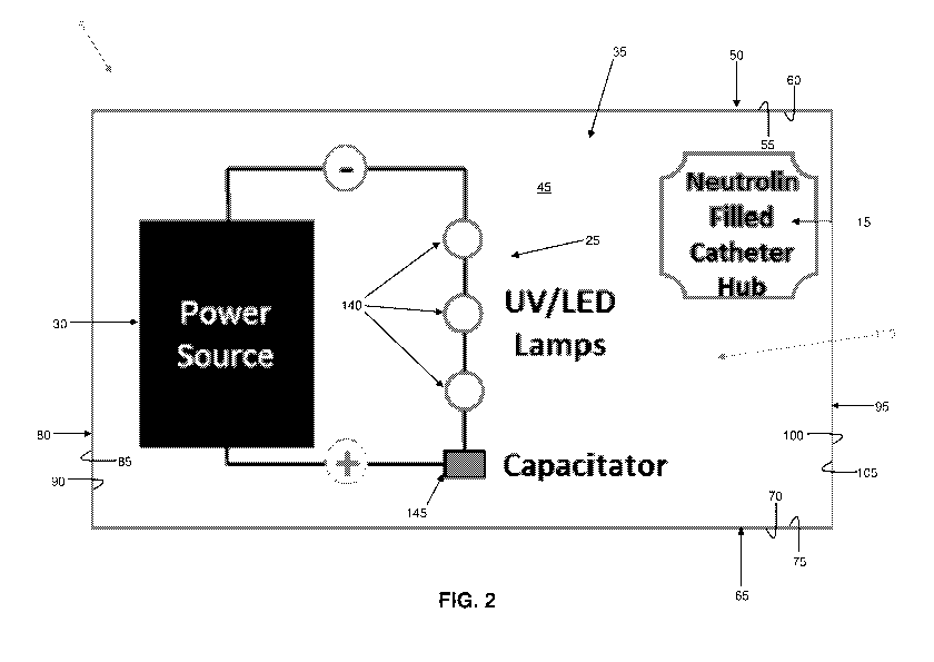
Fig. 2 is a schematic view showing the underside
of the field sterilizer and vascular connector kit
shown in Fig. 1;
Fig. 3 is a schematic view showing details of the
vascular connector which is mounted to the underside
of the field sterilizer and vascular connector kit
shown in Fig. 1; and
Fig. 4 is a schematic view of another vascular
connector which may be used with the field sterilizer
and vascular connector kit of Fig. 1.
Detailed Description Of The Preferred Embodiments
In accordance with the present invention, and
looking now at Figs. 1-3, there is provided a novel UV
sterilizer and vascular connector kit 5 which may be
used for sterilizing a patient's skin and then
CA 03018587 2018-09-20
WO 2017/172803
PCT/US2017/024586
- 16 -
providing sterile vascular access to the vasculature
of a patient. UV sterilizer and vascular connector
kit 5 generally comprises (i) a UV sterilizer 10, and
(ii) a vascular connector 15 with enhanced
antimicrobial action.
1. UV Sterilizer 10
UV sterilizer 10 is compact in size and generally
comprises (i) a housing 20, (ii) a UV light source 25,
and (iii) a power source 30 for powering UV light
source 25. See Figs. 1 and 2.
More particularly, in one preferred form of the
invention, housing 20 generally comprises a panel 35
having a top surface 40 and a bottom surface 45; a
front wall 50 having an outside surface 55 and an
inside surface 60; a back wall 65 having an outside
surface 70 and an inside surface 75; a left side wall
80 having an outside surface 85 and an inside surface
90; and a right side wall 95 having an outside surface
100 and an inside surface 105. Panel 35, front wall
50, back wall 65, left side wall 80 and right side
CA 03018587 2018-09-20
WO 2017/172803
PCT/US2017/024586
- 17 -
wall 95 cooperate with one another as shown in Figs. 1
and 2 so as to form a concave recess 110 on the
underside of housing 20.
Housing 20 is compact in size, e.g., it is
preferably approximately 10 cm long x 6 cm wide x 3 cm
high.
Bottom surface 45 of panel 35, inside surface 60
of front wall 50, inside surface 75 of back wall 65,
inside surface 90 of left side wall 80 and inside
surface 105 of right side wall 95 preferably all
comprise a UV light-reflecting material (e.g., a high
reflectance metal), such that concave recess 110
constitutes a UV light-reflecting chamber. In one
preferred form of the invention, panel 35, front wall
50, back wall 65, left side wall 80 and right side
wall 95 are all formed out of a material which is UV
light-reflecting. In another preferred form of the
invention, panel 35, front wall 50, back wall 65, left
side wall 80 and right side wall 95 are formed out of
a material which is not UV light-reflecting, and they
CA 03018587 2018-09-20
WO 2017/172803
PCT/US2017/024586
- 18 -
are all coated with a material which is UV light-
reflecting.
In one preferred form of the invention, left side
wall 80 also comprises a light baffle 115 and right
side wall 95 comprises a light baffle 117. More
particularly, left side wall 80 comprises an opening
120 which is normally closed off by a UV-opaque
structure 125. However, UV-opaque structure 125 is
constructed so that it may be pushed aside when
desired (e.g., UV-opaque structure 125 may comprise a
curtain, a plurality of bristles, etc.). Similarly,
right side wall 95 comprises an opening 130 which is
normally closed off by a UV-opaque structure 135.
However, UV-opaque structure 135 is constructed so
that it may be pushed aside when desired (e.g., UV-
opaque structure 135 may comprise a curtain, a
plurality of bristles, etc.).
In one preferred form of the invention, housing
may comprise a frame carrying one or more Mylar
20 (or other plastic) sheets, e.g., so that the housing
can be folded along its long axis to provide a more
CA 03018587 2018-09-20
WO 2017/172803
PCT/US2017/024586
- 19 -
compact shape for packaging. In another preferred
form of the invention, housing 20 may comprise a
plurality of self-standing Mylar (or other plastic)
sheets, etc.
UV light source 25 and power source 30 (for
powering UV light source 25) are mounted to bottom
surface 45 of panel 35 so that UV light may be
directed on a skin surface opposing bottom surface 45
of panel 35. UV light source 25 and power source 30
are configured so as to provide a UV dosage to the
skin of the patient which is sufficient to effectively
disinfect the skin of the patient without burning the
skin of the patient. UV light source 25 and power
source 30 are also configured so as to provide the
disinfecting UV dosage in a relatively short period of
time, e.g., 30-60 seconds. UV light source 25
preferably comprises a plurality of UV light-emitting
diodes (LEDs) 140 of the sort well known in the art of
UV disinfection systems. Power source 30 comprises an
appropriate battery (e.g., a 9V battery) for powering
UV light source 25, and may include a capacitor 145
CA 03018587 2018-09-20
WO 2017/172803
PCT/US2017/024586
- 20 -
and various control circuitry (including an on/off
button 150), etc. of the sort well known in the art of
electrical power systems.
Vascular connector 15 is releasably mounted in
concave recess 110 of housing 20 (e.g., vascular
connector 15 is mounted to bottom surface 45 of panel
35) so that vascular connector 15 is readily available
to be installed in a patient after UV sterilizer 10
has been used to sterilize the skin of a patient. In
one preferred from of the invention, vascular
connector 15 is releasably secured to bottom surface
45 of panel 35 by mounting vascular connector 15 to
bottom surface 45 of panel 35 with easily-released
clips of the sort well known in the art of packaging,
or with other releasable securement mechanisms of the
sort well known in the art of packaging.
Concave recess 110 of housing 20 is preferably
closed off with a sterile seal 155 which is removed in
the field at the time of use. By way of example but
not limitation, sterile seal 155 may comprise a pull
sheet which is releasably secured to front wall 50,
CA 03018587 2018-09-20
WO 2017/172803
PCT/US2017/024586
- 21 -
back wall 65, left side wall 80 and right side wall
95. As a result of this construction, the various
components housed in concave recess 110 (e.g.,
vascular connector 15, UV light source 25 and power
source 30) may all be maintained in a sterile
condition until the time of use.
2. Vascular Connector 15
Vascular connector 15 preferably comprises a
standard 3-way stopcock-controlled connector (see Fig.
3). More particularly, vascular connector 15
preferably comprises a hollow tube 160 having a distal
end 165 and a proximal end 170. Proximal end 170 is
in fluid communication with a hollow housing 175.
Hollow housing 175 preferably comprises 3 ports 180
which are in fluid communication with hollow housing
175. Ports 180 are preferably stopcock-controlled
ports. As is well known in the art, vascular
connector 15 is intended to have its distal end 165
positioned within the vasculature of a patient and
ports 180 used to deliver appropriate fluids (e.g.,
CA 03018587 2018-09-20
WO 2017/172803
PCT/US2017/024586
- 22 -
saline, plasma, medications, etc.) to the vasculature
of the patient.
In accordance with the present invention,
vascular connector 15 is pre-filled with an
antimicrobial which is safe to be injected into a
patient. In the preferred form of the invention, the
antimicrobial is Taurolidine, and the Taurolidine is
in solution form (e.g., such as the Taurolidine
catheter lock solution sold by CorMedix Inc. of
Bridgewater, NJ under the trade name NeutrolinC)). The
Taurolidine is contained within hollow tube 160 and
hollow housing 175 of vascular connector 15 by a
removable cap 185 positioned on distal end 165 of
hollow tube 160 and by setting the stopcocks of ports
180 in their closed positions. Additionally, if
desired, removable caps 190 may be positioned on the 3
ports 180. Alternatively, removable cap 185 and/or
removable caps 190 may be replaced by easily-punctured
diaphragms of the sort well known in the art.
If desired, a vascular access guidewire 195 of
the sort well known in the art of catheter access may
CA 03018587 2018-09-20
WO 2017/172803
PCT/US2017/024586
- 23 -
be included with, but not disposed within, vascular
connector 15.
3. Use
1. The site of the intended vascular access is
cleaned of debris - note that there is no requirement
of alcohol or betadine or other antiseptics, the site
may be cleaned with local impure water, or even spit
or urine, or simply brushed off with a cloth or by
hand.
2. Housing 20 of UV sterilizer 10 is unfolded
(if it was packaged in a folded condition) and then
sterile seal 155 is removed from the bottom of housing
of UV sterilizer 10, thereby exposing concave
15 recess 110 of housing 20.
3. Power source 30 is connected to UV light
source 25 (if UV sterilizer 10 was packaged with power
source 30 disconnected from UV light source 25).
4. UV sterilizer 10 is placed against the skin
20 of the patient at the site of the intended vascular
access so that UV light source 25 is directed toward
CA 03018587 2018-09-20
WO 2017/172803
PCT/US2017/024586
- 24 -
the site of the intended vascular access. UV
sterilizer 10 makes a firm connection with the anatomy
of the patient (i.e., the "rim" of concave recess 110
makes a firm connection with the skin of the patient)
so as to avoid any light leakage, with UV opaque
structures 125 and 135 closing off openings 120 and
130 of housing 20, respectively. Note that if UV
sterilizer 10 is being placed on a limb of the
patient, openings 120 and 130 in left side wall 80 and
right side wall 95, respectively, of housing 20 can
receive a portion of the patient's limb so that UV
sterilizer 10 will seat in a stable manner on the
limb. As this occurs, UV-opaque structures 125 and
135 may be pushed aside to the extent required to
accommodate the anatomy of the patient, however, UV-
opaque structures 125 and 135 will prevent UV light
leakage through light baffles 115 and 117,
respectively.
5. UV sterilizer 10 is activated (e.g., by
pushing on/off button 150). When this occurs, UV
light is directed onto the skin of the patient,
CA 03018587 2018-09-20
WO 2017/172803
PCT/US2017/024586
- 25 -
whereby to sterilize the skin of the patient, without
threatening the vision of the caregiver who is
conducting the treatment (and without allowing light
to escape and reveal the location of the patient,
which may be important in military applications).
6. When UV sterilization is completed, UV
sterilizer 10 is turned off (e.g., by pushing on/off
button 150 again), UV sterilizer 10 is removed from
the site of the vascular access, and vascular
connector 15 is removed from bottom surface 45 of
panel 35.
7. Removable cap 185 is removed from distal end
165 of vascular connector 15, distal end 165 of
vascular connector 15 is advanced through the now-
sterile skin surface, and distal end 165 of vascular
connector 15 introduced into the vasculature of the
patient. Note that the Taurolidine contained within
the hollow body of vascular connector 15 provides
antimicrobial action to limit catheter-related
infection. Note that, if desired, vascular access
guidewire 195 may be used to assist in the deployment
CA 03018587 2018-09-20
WO 2017/172803
PCT/US2017/024586
- 26 -
of vascular connector 15, in which case vascular
access guidewire 195 is first passed through the skin
of the patient and into the vasculature of the
patient, and then vascular connector 15 is passed over
vascular access guidewire 195 and through the skin of
the patient and into the vasculature of the patient
(note also that where the proximalmost port 180 of
vascular connecter 15 comprises a stopcock and/or a
cap 190, the stopcock will need to be opened and/or
the cap 190 will need to be removed in order for the
vascular connecter 15 to be loaded over vascular
access guidewire 195). Then vascular access guidewire
195 is withdrawn from vascular connector 15.
8. Once vascular connector 15 has been deployed
in the patient, one or more of ports 180 may be
connected to an appropriate fluid source for delivery
of appropriate fluids (e.g., saline, plasma,
medications, etc.) to the vasculature of the patient.
Note that the Taurolidine contained within the body of
vascular connector 15 may be pushed safely into the
vasculature of the patient ahead of the fluid which is
CA 03018587 2018-09-20
WO 2017/172803
PCT/US2017/024586
- 27 -
to be delivered to the patient. Alternatively, some
or all of the Taurolidine contained within the body of
vascular connector 15 may be removed from the body of
the vascular connector 15 via one or more of the ports
180 prior to introducing a desired fluid into the
vasculature of the patient.
9. Once vascular connector 15 has been deployed
in the vasculature of the patient, UV sterilizer 10
may be used to sterilize another tissue surface (e.g.,
of the same patient or of another patient).
4. Alternative Vascular Connector 15A
In an alternative form of the invention, a
vascular connector 15A (Fig. 4) may be provided.
Vascular connector 15A is substantially the same as
vascular connector 15 described above, except that a
porous disc 200 may be disposed within hollow housing
175 of vascular connector 15A. Porous disc 200 is
formed out of a material which is capable of
containing and releasing an antimicrobial (e.g.,
porous disc 200 may be in the form of a hydrogel web
CA 03018587 2018-09-20
WO 2017/172803
PCT/US2017/024586
- 28 -
or mesh). Porous disc 200 is impregnated with an
antimicrobial. In the preferred form of the
invention, the antimicrobial is a solution of
Taurolidine, such as the Neutrolin0D-heparin 100 unit
catheter lock solution sold by CorMedix Inc., which is
Taurolidine solution containing low-dose heparin
(heparin can be helpful to prevent clotting in
vascular connector 15A, but low-dose heparin may be
preferred since the patient may be bleeding in the
field). If desired, the remaining spaces within the
interior of vascular connector 15A (i.e., the spaces
not taken up with porous disc 200) may also be filled
with the Taurolidine solution.
In addition, the ante-chamber of each port 180
may be filled with a gel formulation which must be
removed or pierced in order to enable flow through
that port. In this way, there are two lines of
defense to prevent infection and biofilm.
Furthermore, a port 180 may have a length of
intravenous tubing pre-connected to that port and pre-
filled with an antimicrobial, e.g., a catheter lock
CA 03018587 2018-09-20
WO 2017/172803
PCT/US2017/024586
- 29 -
solution comprising Taurolidine such as that sold by
CorMedix Inc.
Modifications Of The Preferred Embodiments
It should be understood that many additional
changes in the details, materials, steps and
arrangements of parts, which have been herein
described and illustrated in order to explain the
nature of the present invention, may be made by those
skilled in the art while still remaining within the
principles and scope of the invention.