Note: Descriptions are shown in the official language in which they were submitted.
- 1 -
VEHICLE WITH BRAKE TRACTION CONTROL AND
METHOD FOR CONTROLLING TRACTION OF A VEHICLE
TECHNOLOGICAL FIELD
[0001] The present technology relates to vehicles with brake traction
control and
methods for controlling traction of a vehicle.
BACKGROUND
[0002] Many four-wheel drive vehicles are provided with at least one
open
differential which drives a pair of wheels while allowing the wheels to rotate
independently.
However, when one wheel loses traction, power from the motor follows the path
of least
resistance and applies all torque to the wheel with no or less traction.
[0003] As such many vehicles, especially off-road vehicles, need
traction control in
order to maintain control and movement when encountering slippery ground, due
to weather
and/or terrain conditions. Referred to as traction control, there are
different solutions for
providing power to the wheel with more traction when its opposite wheel has
lost traction.
[0004] In order to provide power to the wheel with more traction,
vehicles are
sometimes provided with a limited slip differential (LSD). Limited slip
differentials allow for
the partial transfer of motor power from a wheel with less traction to its
opposite wheel with
more traction. This is done by limiting the independence between the two
wheels, such that
the amount of power sent to either wheel is limited. In this way, each wheel
always receives
some portion of the power from the motor. Correspondingly, the amount of power
sent to
either wheel is limited, and the amount of power sent to the wheel with more
traction can
never be all of the power from the motor. Limited slip differentials are also
more expensive,
heavier and require more maintenance than an open differential.
[0005] Some vehicles utilize instead a locking differential, where the
differential can
be switched between a locked configuration and an open configuration. In the
locked
configuration, the wheels are locked into the same rate of rotation and both
wheels receive
the same amount of power. In the open configuration, the wheels are allowed to
rotate
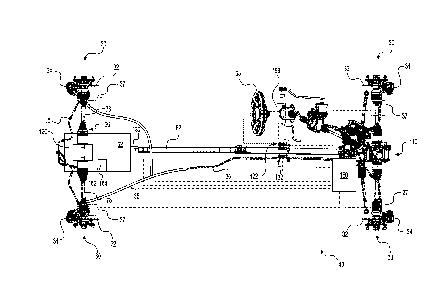
independently, similar to an open differential. In this case, in the locked
configuration,
11905506.1
CA 3018730 2018-09-26
- 2 -
neither wheel can receive more than half of the power from the motor.
Similarly to LSDs,
locking differentials are more expensive, heavier and require more maintenance
than an open
differential.
[0006] Additionally, some vehicles are also provided with the option
of changing
from a 2x4 wheel drive mode to a 4x4 wheel drive mode. In these vehicles, some
sort of
traction control is still desirable for the wheels that receive power from the
motor only when
the vehicle is in 4x4 drive mode. Installing an LSD or a locking differential
on these wheels,
however, adds additional complication, weight, and expense in comparison to an
open
differential. Further, traction control is unnecessary when the wheels are not
being driven.
[0007] There is therefore a desire for a system and method for controlling
traction in a
vehicle, including off-road vehicles, while avoiding at least some of the
above disadvantages.
SUMMARY
[0008] It is an object of the present technology to ameliorate at
least some of the
inconveniences present in the prior art.
[0009] According to an aspect of the present technology, there is provided
a system
and method for selectively implementing brake traction control (BTC) on wheels
driven only
when the vehicle is in a 4x4 drive mode, the wheels being operatively
connected by an open
differential. By sensing the position of a drive mode switch, an ABS module
can selectively
activate BTC only when the drive mode switch indicates that the vehicle is in
4x4 drive
mode. In this way, the wheels are allowed to rotate independently (via the
open differential)
unless the wheels are being driven and traction control is needed. Use of the
open differential
when the wheels are not driven or when there is no need for traction control
benefits the
vehicle by having fewer parts (as the control is implemented electronically
and only in 4x4
drive mode) and so is lighter and requires less maintenance than if traction
controlling
differentials were utilized.
[0010] According to an aspect of the present technology, there is
provided a vehicle
including a frame; a motor connected to the frame; a pair of front suspension
assemblies
connected to the frame; a pair of rear suspension assemblies connected to the
frame; a left
driven wheel and a right driven wheel connected to one of the pair of front
suspension
assemblies and the pair of rear suspension assemblies; a first left brake
assembly operatively
11905506.1
CA 3018730 2018-09-26
- 3 -
connected to the left driven wheel; a first right brake assembly operatively
connected to the
right driven wheel; a left wheel and a right wheel connected to an other one
of the pair of
front suspension assemblies and the pair of rear suspension assemblies; a
second left brake
assembly operatively connected to the left wheel; a second right brake
assembly operatively
connected to the right wheel; an anti-lock braking system (ABS) module for
selectively
controlling the brake assemblies, the ABS module being communicatively
connected to the
first left brake assembly, the first right brake assembly, the second left
brake assembly, and
the second right brake assembly; a transmission operatively connected to the
motor for
receiving torque from the motor, the left and right driven wheels being
operatively connected
to the transmission; a drive mode coupler connected between the transmission
and the left
and right wheels, the drive mode coupler causing the vehicle to change between
a 2x4 drive
configuration and a 4x4 drive configuration by selectively coupling the
transmission and the
left and right wheels for selectively driving the left and right wheels; and a
drive mode switch
operatively connected to the drive mode coupler, a position of the drive mode
switch being
selectively moveable between a 2x4 position and a 4x4 position, the drive mode
switch being
communicatively connected to the ABS module, the drive mode switch causing the
drive
mode coupler to change to one of the 2x4 drive configuration and the 4x4 drive
configuration
when the drive mode switch is moved to a corresponding one of the 2x4 position
and the 4x4
position, the ABS module selectively performing brake traction control of at
least one of the
left wheel and the right wheel based on the position of the drive mode switch.
[0011] In some implementations, the ABS module selectively performs
brake traction
control of the at least one of the left wheel and the right wheel when the
drive mode switch is
in the 4x4 position.
[0012] In some implementations, no brake traction control is performed
on the at least
one of the left wheel and the right wheel when the drive mode switch is in the
2x4 position.
[0013] In some implementations, the vehicle further includes a first
differential
operatively connected between the left wheel and the right wheel, the first
differential being
an open differential.
[0014] In some implementations, the vehicle further includes a second
differential
operatively connected between the transmission and the left and right driven
wheels, the
11905506.1
CA 3018730 2018-09-26
- 4 -
second differential being a locking differential changeable between a locked
differential
mode and an unlocked differential mode.
[0015] In some implementations, the ABS module further selectively
performs
traction control on the left driven wheel and the right driven wheel when the
second
differential is in the unlocked differential mode.
[0016] In some implementations, the vehicle further includes a
differential switch
communicatively connected to a controller communicatively connected to the
second
differential, the controller selectively changing the second differential to
one of the locked
differential mode and the unlocked differential mode when the differential
switch is moved to
a corresponding one of a locked mode position and an unlocked mode position.
[0017] In some implementations, the vehicle is a side-by-side vehicle
comprising a
dashboard; and the differential switch is a manual switch disposed on the
dashboard.
[0018] In some implementations, the vehicle is an all-terrain vehicle
comprising a
handlebar; and the differential switch is a manual switch disposed on the
handlebar.
[0019] In some implementations, the vehicle is a side-by-side vehicle
comprising a
dashboard; and the drive mode switch is a manual switch disposed on the
dashboard.
[0020] In some implementations, the vehicle is an all-terrain vehicle
comprising a
handlebar; and the drive mode switch is a manual switch disposed on the
handlebar.
[0021] In some implementations, the vehicle further includes a
plurality of speed
sensors operatively connected to at least the left and right wheels, the
plurality of speed
sensors being communicatively connected to the ABS module; and at least one of
a throttle
position sensor communicatively connected to the ABS module, a pedal position
sensor
communicatively connected to the ABS module, and an engine control module for
determining engine torque output communicatively connected to the ABS module.
[0022] In some implementations, the vehicle is a side-by-side vehicle
(SSV); and
further includes two seats connected to the frame, the two seats being
disposed side by side; a
roll cage connected to the frame and extending at least partially over the two
seats; and a
steering wheel operatively connected to one of: the left and right wheels, and
the left and
right driven wheels.
11905506.1
CA 3018730 2018-09-26
- 5 -
[0023] In some implementations, the vehicle is an all-terrain vehicle
(ATV); and
further includes a straddle seat connected to the frame; and a handlebar
operatively connected
to one of: the left and right wheels, and the left and right driven wheels.
[0024] According to an aspect of the present technology, there is
provided a method
for controlling traction of a vehicle, the vehicle having: a motor; a left
driven wheel and a
right driven wheel coupled to and driven by the motor, the left and right
driven wheels being
one of front wheels of the vehicle and rear wheels of the vehicle; and a left
wheel and a right
wheel, the left and right wheels being an other one of the front wheels and
the rear wheels.
The method includes sensing a position of a drive mode switch, the drive mode
switch having
a 2x4 position and a 4x4 position; when the drive mode changes from a 2x4
position to a 4x4
position: coupling the left and right wheels to the motor; determining that at
least one of the
left and right wheels is slipping; and causing an anti-lock braking system
(ABS) module of
the vehicle to perform brake traction control on at least one of the left
wheel and the right
wheel; and when the drive mode changes from a 4x4 position to a 2x4 position:
uncoupling
the left and right wheels from the motor.
[0025] In some implementations, determining that at least one of the
left and right
wheels is slipping includes determining that an engine torque indicator is
above a pre-
determined engine threshold; and in response to the engine torque indicator
being above the
pre-determined engine threshold, causing the ABS module to perform brake
traction control
on the at least one of the left wheel and the right wheel.
[0026] In some implementations, determining that the engine torque
indicator is
above the pre-determined engine threshold includes at least one of:
determining, by a throttle
valve position sensor, a throttle position value; determining, by an engine
control module, an
engine torque output; and determining, by a pedal position sensor, a pedal
position value.
[0027] In some implementations, determining that at least one of the left
and right
wheels is slipping includes determining that an effective speed differential
between the left
wheel and the right wheel is above a pre-determined speed threshold; and in
response to the
effective speed differential being above the pre-determined speed threshold,
causing the ABS
module to perform brake traction control on the at least one of the left wheel
and the right
wheel.
11905506.1
CA 3018730 2018-09-26
- 6 -
[0028] In some implementations, causing the ABS module of the vehicle
to perform
brake traction control includes determining an effective speed differential
between the left
wheel and the right wheel; determining a steering angle by a position sensor
operatively
connected to a steering assembly of the vehicle; and based on the effective
speed differential
and the steering angle, controlling a pressure applied to the at least one of
the left wheel and
the right wheel by the ABS module performing brake traction control on the at
least one of
the left wheel and the right wheel.
[0029] In some implementations, determining the effective speed
differential includes
determining a speed of rotation of the left wheel; determining a speed of
rotation of the right
wheel; and determining a speed of travel of the vehicle.
[0030] In some implementations, causing the ABS module of the vehicle
to perform
brake traction control includes determining that a locking differential is in
an unlocked
differential mode, the locking differential being connected between the left
driven wheel and
the right driven wheel, the locking differential being selectively changeable
between a locked
differential mode and the unlocked differential mode; and in response to the
locking
differential being in the unlocked differential mode, further causing the ABS
module to
perform brake traction control on at least one of the left driven wheel and
the right driven
wheel.
[0031] For purposes of this application, terms related to spatial
orientation such as
forwardly, rearward, upwardly, downwardly, left, and right, are as they would
normally be
understood by a driver of the vehicle sitting thereon in a normal riding
position.
[0032] Implementations of the present technology each have at least
one of the above-
mentioned object and/or aspects, but do not necessarily have all of them. It
should be
understood that some aspects of the present technology that have resulted from
attempting to
attain the above-mentioned object may not satisfy this object and/or may
satisfy other objects
not specifically recited herein.
[0033] Additional and/or alternative features, aspects and advantages
of
implementations of the present technology will become apparent from the
following
description, the accompanying drawings and the appended claims.
11905506.1
CA 3018730 2018-09-26
- 7 -
BRIEF DESCRIPTION OF THE DRAWINGS
[0034] For a better understanding of the present technology, as well
as other aspects
and further features thereof, reference is made to the following description
which is to be
used in conjunction with the accompanying drawings, where:
[0035] Figure 1 is a top, front, left side perspective view of a side-
by-side vehicle;
[0036] Figure 2 is a left side elevation view of portions of the
vehicle of Figure 1;
[0037] Figure 3 is a top, rear, right side perspective view of a
motor, driveshafts,
brake assemblies, and steering assembly of the vehicle of Figure 1;
[0038] Figure 4 is a top plan view of the components of Figure 3;
[0039] Figure 5 is a top plan view of the components of Figure 3 with
schematic
illustration of a control system of the vehicle of Figure 1 and with the motor
having been
removed;
[0040] Figure 6 is a flow chart illustrating a method for controlling
traction of the
vehicle of Figure 1;
[0041] Figure 7 is a flow chart illustrating additional portions of
the method of Figure
6;
[0042] Figure 8 is a left side elevation view of an all-terrain
vehicle; and
[0043] Figure 9 is a schematic representation of portions of the
vehicle of Figure 8.
DETAILED DESCRIPTION
[0044] The present technology will be described with respect to four-
wheel, off-road
vehicles, both a vehicle having two side-by-side seats and a steering wheel
(i.e. a side-by-side
vehicle (SSV)) and a vehicle having a handlebar and a straddle seat (i.e. an
all-terrain vehicle
(ATV)). However, it is contemplated that at least some aspects of the present
technology may
apply to other types of vehicles such as, but not limited to, off-road
vehicles having more
11905506 1
CA 3018730 2018-09-26
- 8 -
than four wheels, and on-road vehicles having four or more wheels and having
one or more
seats.
[0045] The general features of an off-road vehicle 40, specifically a
side-by-side
vehicle (SSV) 40, will be described with respect to Figures 1 and 2. The
vehicle 40 has a
frame 42. The frame 42 defines a central cockpit area 52 inside which are
disposed a driver
seat 54 and a passenger seat 56. In the present implementation, the driver
seat 54 is disposed
on the left side of the vehicle 40 and the passenger seat 56 is disposed on
the right side of the
vehicle 40. However, it is contemplated that the driver seat 54 could be
disposed on the right
side of the vehicle 40 and that the passenger seat 56 could be disposed on the
left side of the
vehicle 40. It is also contemplated that the vehicle 40 could include a single
seat for the
driver, or a larger number of seats, or a bench accommodating the driver and
at least one
passenger. The vehicle 40 also includes a roll cage 43 connected to the frame
42 and
extending at least partially over the seats 54, 56.
[0046] The vehicle 40 includes left and right front wheels 44
connected to the frame
42 by a pair of front suspension assemblies 46. Left and right rear wheels 48
are connected to
the frame 42 by a pair of rear suspension assemblies 50. Each one of the front
and rear
wheels 44, 48 has a rim 45 and a tire 47. The rims 45 and tires 47 of the
front wheels 44 may
differ in size from the rims and tires of the rear wheels 48.
[0047] The vehicle 40 includes a steering wheel 58 operatively
connected to the front
wheels 44 for controlling an angle of the front wheels 44. The driver operates
the steering
wheel 58 from the driver seat 54. The steering wheel 58 is disposed in front
of the driver seat
54. A steering position sensor 158 is operatively connected to the steering
wheel 58, via a
steering assembly, for determining a steering angle of the front wheels 44.
The vehicle 40
also includes a dashboard 55 disposed forward of the seats 54, 56. A throttle
operator in the
.. form of a throttle pedal 91 is disposed over the floor of the cockpit area
52 below the steering
wheel 58 and in front of the driver seat 54. A pedal position sensor 93 is
operatively
connected to the throttle pedal 91 to sense movement of the pedal 91 caused by
the driver in
operation.
[0048] As can be seen in Figure 2, a motor 62 is connected to the
frame 42 in a rear
portion of the vehicle 40. In the present implementation, the motor 62 is an
internal
combustion engine but the present technology is not so limited. It is
contemplated that the
11905506.1
CA 3018730 2018-09-26
- 9 -
engine 62 could be replaced by a hybrid or electric motor in some
implementations. The
vehicle 40 includes an engine control module (ECM) 162 (Fig. 5) for monitoring
and
controlling various operations of the engine 62. The ECM 162 is
communicatively connected
to the pedal position sensor 93 for receiving signals for controlling a
throttle valve (not
.. shown) of the engine 62. The engine 62 further includes a throttle position
sensor 164 (Fig. 5)
operatively connected to the throttle valve and communicatively connected to
the ECM 162
for monitoring the position of the throttle valve.
[0049] With further reference to Figures 3 to 5, the vehicle 40
includes four brake
assemblies 30. One brake assembly 30 is operatively connected to each of the
wheels 44, 48.
Each brake assembly 30 includes a brake disc 32 and a caliper 34 disposed
around its
corresponding brake disc 32. Each caliper 34 is connected to a corresponding
brake line 35.
The brake lines 35 are operatively connected to a brake pedal (not shown) of
the vehicle 40.
The brake lines 35 are further connected to an anti-lock braking system (ABS)
module 150,
which will be described in more detail below. Each caliper 34 includes a pair
of brake pads
.. positioned on opposite sides of its respective brake disc 32. The brake
assemblies 30 are
actuated by actuating the calipers 34 by application of a fluid pressure in
the brake lines 35,
thereby causing the brake pads to apply pressure on their respective brake
discs 32.
[0050] The motor 62 is connected to a transmission 64, specifically a
continuously
variable transmission (CVT) 64 disposed on a left side of the motor 62. The
CVT 64 is
operatively connected to a transaxle 66 to transmit torque from the motor 62
to the transaxle.
The transaxle 66 is operatively connected to the front and rear wheels 44, 48
to propel the
vehicle 40. The motor 62 and the transmission 64 are supported by the frame
42. Variants of
the vehicle 40 having other transmission types are contemplated.
[0051] The transaxle 66 is mechanically connected to a shifter 60
disposed laterally
between the two seats 54, 56. The shifter 60 allows the driver to select from
a plurality of
combinations of engagement of gears of the transaxle, commonly referred to as
gears. In the
present implementation, the shifter 60 allows the driver to select between a
reverse gear, two
forward gears (high and low) and a neutral position in which the transaxle
does not transmit
torque to the wheels 44, 48. It is contemplated that other types of
connections between the
.. shifter 60 and the transaxle 66 could be used.
11905506 1
CA 3018730 2018-09-26
- 10 -
[0052] The transaxle 66 transmits the torque applied thereon to drive
the left and right
rear wheels 48. While the vehicle 40 is described with the rear wheels 48
driving the vehicle
40 when in 2x4 drive mode, it is contemplated that the front wheels 44 could
be driven when
the vehicle 40 is in 2x4 drive mode in some implementations. Specifically, the
transaxle 66
includes left and right half-shafts 78 and a differential 120 connected
therebetween for
applying torque to the rear driven wheels 48. The differential is operatively
connected
between the transmission 64 and the left and right driven wheels 48.
[0053] The differential 120 is a locking differential 120 changeable
between a locked
differential mode and an unlocked differential mode. The locked differential
mode locks the
rotation of the wheels 48 to the same rate of rotation, while the unlocked
mode allows the
wheels 48 to rotate independently (similarly to an open differential).
[0054] The vehicle 40 also includes a differential switch 122 provided
in the vicinity
of a driver in the vehicle 40. In the present implementation, the switch 122
is disposed on the
dashboard 55. The differential switch 122 is a toggle switch 122 having two
(2) positions: a
locked mode position for manually locking the differential 120 and an unlocked
mode
position for unlocking the differential 120. The differential 120 includes a
controller (not
separately numbered) communicatively connected to the differential switch 122.
The
controller selectively changes the differential 120 to the locked differential
mode or the
unlocked differential mode when the differential switch 122 is moved to the
locked mode
position or the unlocked mode position, respectively. In some implementations,
the
differential switch 122 could be connected to the ECM 162 and the ECM 162
could control
the mode of the differential 120.
[0055] In some implementations, the differential switch 122 could be
omitted and
control systems of the vehicle 40 could automatically control the locking and
unlocking of
the differential 120. It is also contemplated that the control systems of the
vehicle 40 could
automatically control the locking and unlocking of the differential 120 in
addition to control
of the differential 120 with the differential switch 122.
[0056] In the present technology, the transmission 64 is selectively
connected to the
front wheels 44 via a drive mode coupler 130, shown schematically in Figure 4.
The drive
mode coupler 130 causes the vehicle 40 to change from a 2x4 drive
configuration to a 4x4
11905506.1
CA 3018730 2018-09-26
- 11 -
drive configuration by selectively coupling the front left and right wheels 44
to the
transmission 64 for selectively driving the front wheels 44.
[0057] When the drive mode coupler 130 selectively couples the front
left and right
wheels 44 to the transmission 64, the torque is transferred from the motor 62
to a series of
driveshafts 82, in addition to applying a portion of the torque on the rear
half shafts 78. A
front end of the series of driveshaft 82 is connected to a differential 110.
The differential 110
is operatively connected between the left and right front wheels 44 via left
and right half-
shafts 77. The differential 110 is an open differential 110, allowing the
wheels 44 to rotate
independently.
[0058] The selection between the 2x4 drive configuration and the 4x4 drive
configuration is made using a drive mode switch 132 provided in the vicinity
of the driver in
the vehicle 40. The drive mode switch 132 is connected to the EM 162, which is
connected to
an actuator for moving the drive mode coupler 130. As such, the drive mode
switch 132 is
operatively connected to the drive mode coupler 130 for selectively
controlling the drive
mode coupler 130. The drive mode switch 132 is a toggle switch 132 mounted on
the
dashboard 55 of the vehicle 40 (shown isolated from the dashboard 55 in Figure
4), next to
the differential switch 122. The switch 132 has two (2) positions: a 2x4
position for selecting
the 2x4 drive configuration and a 4x4 position for selecting the 2x4 drive
configuration. It is
contemplated that the switches 122, 132 could be different types of control
mechanisms,
including for example rotary knobs or press buttons. It is contemplated that
the switches 122,
132 could be differently located in the vehicle 40, for example on the
steering wheel 58. It is
further contemplated that the vehicle 40 could include additional switches for
selecting
addition modes of vehicle control, for example a mud mode, a sand mode, a snow
mode, and
the like. In some implementations, the additional switch could be combined
with the drive
mode switch 132 in order to only be activated when the drive mode switch 132
is in the 4x4
drive mode.
[0059] As indicated above, the vehicle 40 includes an anti-lock
braking system (ABS)
module 150 for selectively controlling the brake assemblies 30. The vehicle 40
includes four
speed sensors 37, one sensor 37 operatively connected to each of the wheels
44, 48. Each
speed sensor 37 is communicatively connected to the ABS module 150. In some
implementations, the two rear wheel speed sensors 37 could be replaced by one
speed sensor
37 to monitor the speed of the transaxle 66. The ABS module 150 is further
communicatively
11905506.1
CA 3018730 2018-09-26
- 12 -
connected to the drive mode switch 132, the differential switch 122, steering
position sensor
158, the pedal position sensor 93, the throttle position sensor 164, and the
ECM 162 for
receiving information therefrom, and where applicable, sending information
thereto.
[0060] The operation of the ABS, by the ABS module 150, will now be
briefly
described. During operation, the ABS uses wheel speed signals received by the
ABS module
150 from the wheel speed sensors 37 (schematically illustrated in Figure 4)
that detect the
speed of rotations of the wheels 44, 48. The ABS module 150 detects the onset
of locking of
one of the brake assemblies 30 when one of the wheel speed sensors 37 reports
a significantly
lower wheel speed than the other speed sensors 37. When this happens, the ABS
module 150
causes a valve (not shown) connected to the brake assembly 30 that is locked
or about to
become locked to modulate the pressure applied by the corresponding caliper 34
on the disc
32, by repeatedly closing and opening the valve to repeatedly reduce or
release and then re-
apply brake pressure in the corresponding brake line 35 until the wheel 44, 48
connected to
the brake assembly 30 that was locked or about to become locked rotates again
at about the
same speed as the other wheels 44, 48. As such, the ABS module 150 controls
operation of
the valves by opening and closing them cyclically for preventing locking of
the brake
assemblies 30. It is contemplated that this control could be applied to two or
more of the
brake assemblies 30 at the same time.
[0061] In the present technology, the ABS module 150 is further
adapted to perform
brake traction control (BTC) of the wheels 44. The BTC is activated based on
the position of
the drive mode switch 132, as will be described in more detail below. In some
implementations, the ABS module 150 is also adapted to perform BTC on the rear
wheels 48
based on the position of the drive mode switch 132.
[0062] BTC performed by the ABS module 150 will first be described in
general
terms. BTC, having been activated based on the position of the drive mode
switch 132, starts
acting when one of the speed sensors 37 reports a significantly higher speed
than the other
speed sensors 37, indicating that a corresponding wheel 44, 48 is slipping. In
response, the
ABS module 150 causes brake pressure to be applied to the brake assembly 30
that
corresponds to the slipping wheel 44, 48 by opening the corresponding valve
(similarly to the
anti-lock braking described above). As in the case of ABS operation, the ABS
module 150
may modulate the brake pressure applied to the brake assembly 30 of the
slipping wheel 44,
48, by repeatedly closing and opening the valve to repeatedly reduce or
release and then re-
11905506.1
CA 3018730 2018-09-26
- 13 -
apply brake pressure in the corresponding brake line 35 until the wheel 44, 48
that was
slipping gains traction and starts rotating again at about the same speed as
its paired wheel
44, 48. Specifically, by blocking movement of the slipping wheel 44, 48,
torque that was
directed by the corresponding differential 110, 120 (because the slipping
wheel 44, 48 was
the path of least resistance) is instead transferred to the oppositely
arranged wheel 44, 48
(which is the least of least resistance when the slipping wheel 44, 48 is
blocked by the brake
assembly 30).
[0063] According to the present technology, the ABS module 150
selectively
performs BTC based on the position of the drive mode switch 132. Specifically,
the ABS
module 150 senses the position of the drive mode switch 132 and then
selectively activates
BTC on the front wheels 44 only when the drive mode switch 132 is in the 4x4
position.
After having been activated based on the switch position and upon detecting
loss of traction
of one of the front wheels 44, the ABS module 150 will control the
corresponding brake
assembly 30 to transfer power to the opposite wheel 44.
[0064] When the ABS module 150 senses that the drive mode switch 132 is in
the
2x4 position, however, no BTC is performed on the front wheels 44. In the
present
implementation, the ABS module 150 also performs no BTC on the rear driven
wheels 48
when the drive mode switch 132 is in the 2x4 position. It is contemplated,
however, that the
ABS module 150 could be adapted for performing BTC on the rear driven wheels
48 when
the drive mode switch 132 is in the 2x4 position and the differential 120 is
in the unlocked
position.
[0065] In order to determine when to initiate controlling the brake
assemblies 30 as
described generally above, the ABS module 150 receives information from the
speed sensors
37, the steering position sensor 158, the pedal position sensor 93, the
throttle position sensor
164, and the ECM 162. In some implementations, in addition to information from
the speed
sensors 37, the ABS module 150 could receive information from only one or more
of the
pedal position sensor 93, the steering position sensor 158, the throttle
position sensor 164,
and the ECM 162. It is contemplated, for example, that the pedal position
sensor 93 and/or
the throttle position sensor 164 could be omitted in some implementations.
[0066] With further reference to Figures 6 and 7, controlling traction of
the vehicle 40
using BTC according to the present technology will now be described in terms
of a method
11905506.1
CA 3018730 2018-09-26
- 14 -
200. While the method 200 will be described as being performed by the ABS
module 150, it
is contemplated that the method 200 could be carried out by another computer-
implemented
controller in communication with the ABS module 150, including but not limited
to the ECM
162. It is also contemplated that different portions of the method 200 could
be performed by
different computer-implemented controllers of the vehicle 40.
[0067] The method 200 begins at step 210 with sensing the position of
the drive mode
switch 132 by the ABS module 150. As is described above, the ABS module 150
only
performs BTC on the wheels 44, 48 when the drive mode switch 132 is in the 4x4
position.
[0068] When it is sensed that the drive mode switch 132 changes from
the 4x4
position to the 2x4 position at step 210, the method 200 continues at step 220
with
uncoupling the front wheels 44 from the motor 62 by sending a message to the
drive mode
coupler 130. Following step 220, the method 200 terminates. The method 200
will then start
again when the position of the drive mode switch 132 is changes from the 2x4
position to the
4x4 position and the method 200 senses the position of the drive mode switch
132 once again
at step 210.
[0069] When the method 200 determines at step 210 that the drive mode
switch 132
changes from the 2x4 position to the 4x4 position, the method 200 continues at
step 230 with
coupling the front wheels 44 to the motor 62 by sending a message to the drive
mode coupler
130.
[0070] The vehicle 40 now being in the 4x4 drive configuration, the method
200 then
continues at step 240 with determining that one of the wheels 44 has begun
slipping, or
loosing traction. Specifically the ABS module 150 begins monitoring the
slippage of the
wheels 44 at step 240. It should be noted that the ABS module 150 may not act
on the brake
assemblies 30 immediately following step 230; the vehicle 40 could have full
traction on both
of the wheels 40 and not require brake manipulation.
[0071] The method 200 then continues at step 250 with causing the ABS
module 150
to perform BTC on at least one of the front wheels 44, slippage of one of the
wheels 44
having been detected at step 240. The method 200 generally continues with
steps 240 and
250, with the ABS module 150 providing BTC to the front wheels 44 when
slippage is
detected, until the ABS module 150 determines that the drive mode switch 132
has changed
position.
11905506.1
CA 3018730 2018-09-26
- 15 -
[0072] Determining that the wheel 44 is slipping by the ABS module 150
at step 240
includes determining, at sub-step 242, that an engine torque indicator is
above a pre-
determined engine threshold. The pre-determined engine threshold of the engine
torque
indicator provides confirmation to the ABS module 150 that torque is being
solicited from the
engine 62 and that the wheels 44, 48 are generally meant to be propelling the
vehicle 40. It is
contemplated that determining that the engine torque indicator is above the
pre-determined
threshold could similarly determine that a much higher engine torque is being
requested than
corresponds to the actual travel speed of the vehicle 40, in connection with
the speed sensors
37 and/or another method of determining travel speed of the vehicle 40.
[0073] The engine torque indicator can be one or more of throttle position
value of
the throttle valve, an engine torque output, and pedal position value. Thus
determining that
the engine torque indicator is above the pre-determined threshold can include
one or more of
determining the throttle position value by the throttle valve position sensor
164, determining
the engine torque output by the ECM 162, and determining the pedal position
value by the
pedal position sensor 93. It is contemplated that different measures of engine
torque could be
used in determining the engine torque indicator.
[0074] As is briefly described above, when one of the speed sensors 37
indicates a
significantly higher speed than the other speed sensors 37, this generally
indicates that its
corresponding wheel 44 is slipping. As the relative speed between the wheels
44 can vary for
reasons other than loss of traction, an effective speed differential can be
compared to a pre-
determined speed threshold. The pre-determined speed threshold provides a
limit above
which the speed differential will likely indicate wheel slippage. Determining
that one of the
wheels 44 is slipping at step 240 also includes determining, at sub-step 244,
that an effective
speed differential between the front wheels 44 is above a pre-determined speed
threshold.
The effective speed differential is found by determining speed of each wheel
44 is measured
by its corresponding speed sensor 37, and the ABS module 150 determines the
speed
differential based on the information received from the speed sensors 37.
[0075] The method 200 further includes determining the speed of travel
of the vehicle
40. As a small speed differential between the wheels 44 is more likely to
indicate slippage at
low travel speeds of the vehicle 40 than the same numerical speed differential
at a higher
travel speeds, the measured speed differential is further compared to the
travel speed of the
vehicle 40 to determine an effective speed differential. If the effective
speed differential
11905506.1
CA 3018730 2018-09-26
- 16 -
exceeds the pre-determined threshold, the ABS module 150 then acts on the
brake assemblies
30 to perform BTC as described above.
[0076] In some implementations, the steering angle as measured by the
steering
position sensor 158 could be taken into consideration for determining the
effective speed
differential. When the vehicle 40 is turning, the wheels 44 will generally
have different
rotational speeds and the absolute speed differential between the two wheels
44 depends on
not only the travel speed of the vehicle 40, but also the steering angle of
the wheels 44. In
order to determine if a speed differential is due to turning or slipping, the
steering angle as
measured by the steering position sensor 158 could thus be taken into
consideration for
determining the effective speed differential.
[0077] The method 200 then continues at step 250 with causing the ABS
module 150
to perform BTC on at least one of the front wheels 44, slippage of one of the
wheels 44
having been detected at step 240. The method 200 generally continues with
steps 240 and
250, with the ABS module 150 providing BTC to the front wheels 44 when
slippage is
detected, until the ABS module 150 determines that the drive mode switch 132
has changed
position.
[0078] In some implementations, the method 200 continues with
determining the
pressure that should be applied to the brake assembly 30 of the wheel 44 that
is slipping. In
such a case, causing the ABS module 150 to perform BTC includes at sub-step
245
determining the effective speed differential. The sub-step 245 is performed
generally as
described above in reference to sub-step 244 and will not be described again.
It is
contemplated that determining the effective speed differential at sub-step 245
could include
different, fewer, or additional factors in the speed differential calculation.
Then at sub-step
246, the steering angle is determined by the steering position sensor 158
operatively
connected to the steering wheel 58. Based on the effective speed differential
and the steering
angle, the method 200 continues at sub-step 248 with controlling the pressure
applied to the
slipping wheel 44 by the ABS module 150 performing BTC.
[0079] In some implementations, causing the ABS module 150 to perform
BTC at
step 250 further includes determining that the differential 120 is in the
unlocked differential
mode. In response, the method 200 further includes causing the ABS module 150
to perform
BTC on the rear wheels 48. As is mentioned above, in some implementations, the
ABS
11905506.1
CA 3018730 2018-09-26
- 17 -
module 150 could perform BTC on the rear wheels 48 when the differential 120
is in the
unlocked differential mode and the drive mode switch 132 is in the 2x4
position in a manner
similar to the way BTC is performed on the front wheels 44 as described above.
[0080] It is contemplated that the method 200 could include additional
or different
steps, either to perform additional functions and/or to perform the steps
described above. It is
contemplated that the steps 242 and 244 could be performed in either order or
simultaneously
and is not limited to the order set forth in the explanation above. Similarly,
it is contemplated
that the steps 244 and 246 could be performed in either order or
simultaneously and is not
limited to the order set forth in the explanation above.
[0081] The present technology, described above with respect to the side-by-
side
vehicle 40, is similarly applicable to straddle-type all-terrain vehicles.
With reference to
Figures 8 and 9, a straddle-type all-terrain vehicle (ATV) 300 will now be
briefly described.
Elements of the present technology as it applies to the ATV 300 that are
similar to those of
the SSV 40 will generally not be described again herein.
[0082] The ATV 300 has a front end 302 and a rear end 304 defined
consistently with
a forward travel direction of the ATV 300. The ATV 300 has a frame 312 to
which is
mounted a motor 316 for powering the ATV 300, specifically an internal
combustion engine
316 in the present implementation. It is contemplated that the ATV 300 may be
powered by
other types of motors, being for example powered by an electric motor.
[0083] The ATV 300 has two front wheels 318 and two rear wheels 320. The
two
front wheels 318 are suspended from the frame 312 by respective front
suspension assemblies
324. Similarly, the two rear wheels 320 are suspended from the frame 312 by
respective rear
suspension assemblies 326. Each wheel 318, 320 includes a brake assembly 380,
as is
illustrated in Figure 9. The brake assemblies 380 are similar to the brake
assemblies 30 of the
SSV vehicle 40, but it is contemplated that different types of brake
assemblies could be used
depending on the implementation.
[0084] The ATV 300 further includes a straddle seat 328 mounted to the
frame 312
for accommodating a driver of the ATV 300. Driver footrests 350 are provided
on either of
the driver seat 328 and are disposed vertically lower than the driver seat 328
to support the
driver's feet. Another straddle seat 334 is provided behind the driver seat
328 to
11905506 1
CA 3018730 2018-09-26
- 18 -
accommodate a passenger. It is contemplated that the ATV 300 could include on
the driver
seat 328 in some implementations.
[0085] A steering assembly 330, including a handlebar 332, is
rotationally supported
by the frame 312 to enable a driver to steer the ATV 300. The steering
assembly 330 is
operably connected to the front left and right wheels 18, through a steering
column (not
shown) in order to steer and turn the ATV 300.
[0086] Similarly to the SSV vehicle 40 described above, the ATV 300
can be
operated in the 2x4 drive configuration or in the 4x4 drive configuration. In
the 2x4 drive
configuration, the rear wheels 320 are driven by the engine 316. In the 4x4
drive
configuration, both the front wheels 318 and the rear wheels 320 are driven.
The ATV 300
includes a drive mode coupler (not shown) operatively connected between the
engine 316 and
the front wheels 318. The drive mode coupler selectively couples the
transmission (not
shown) and the front wheels 318for selectively driving the front wheels 318 in
addition to the
rear wheels 320. The drive mode coupler is controlled by a manual drive mode
switch 340
disposed on the handlebar 332. The ATV 300 also includes a differential switch
345 for
selectively controlling a locking differential (not shown) connected between
the front wheels
318. As described above with respect to the switch 122, the switch 345 is a
manual switch
345 disposed on the handlebar 332, which allows a rider to switch between
locked and
unlocked modes of the differential.
[0087] The ATV 300 also includes an ABS module 390 operatively connected to
each
brake assembly 380. The ABS module 390 operates generally same as the ABS
module 150
and performs the method 200 for the ATV 300, mutatis mutandis. The ABS module
390 is
communicatively connected to the drive mode switch 340 on the handlebar 330 in
order to
determine the position of the switch 340. As described above for the vehicle
40, the ABS
module 390 selectively performs BTC based on the position of the drive mode
switch 340.
The ABS module 390 selectively performs BTC on the front wheels 318 when the
drive
mode switch 340 is in the 4x4 position.
[0088] Modifications and improvements to the above-described
implementations of
the present technology may become apparent to those skilled in the art. The
foregoing
description is intended to be exemplary rather than limiting. The scope of the
present
technology is therefore intended to be limited solely by the scope of the
appended claims.
11905506.1
CA 3018730 2018-09-26