Note: Descriptions are shown in the official language in which they were submitted.
CA 03018944 2018-09-25
DESCRIPTION
Title of Invention: BRAKE FLUID PRESSURE CONTROL DEVICE FOR VEHICLE
Technical Field
[0001]
The present invention relates to a brake fluid pressure
control device for a vehicle that determines whether the state of
a traveling road surface is bad.
Background Art
[0002]
An anti-lock brake system (ABS) is a device that prevents
wheels from being locked. There is a known technique, disclosed
in, for example, PTL 1, that determines whether the state
(concavo-convex road surface) of a traveling road surface is bad
in, for example, a motorcycle.
[0003]
The technique in PTL 1 determines that the road state is bad
when the number of times the wheel acceleration becomes equal to
or more than a predetermined level (L1) is equal to or more than
a predetermined number (KN1).
By the way, change of wheel speed during travel on a bad road
is likely to vary depending on the magnitude of a braking power.
1
CA 03018944 2018-09-25
However, since determination conditions are constant in the
technique in PTL 1, further improvement of determination precision
has been desired.
Citation List
Patent Literature
[0004]
PTL 1: Japanese Patent No. 2928890
Summary of Invention
Technical Problem
[0005]
An object of the invention is to provide a brake fluid pressure
control device for a vehicle capable of improving the precision of
bad road determination.
Solution to Problem
[0006]
According to a first aspect of the invention, there is provided
a brake fluid pressure control device for a vehicle capable of
performing fluid pressure control of a brake fluid pressure applied
to a wheel brake, the brake fluid pressure control device including
wheel speed acquisition means that acquires a wheel speed; slippage
amount calculation means that calculates a slippage amount of a
2
wheel; and bad road determination means that determines whether
a state of a traveling road surface is bad, in which the bad road
determination means determines whether the state of the traveling
road surface is bad using a value related to wheel behavior
calculated based on at least the wheel speed and a bad road
determination threshold value and changes the bad road
determination threshold value according to the slippage amount
of the wheel.
[0007]
According to a second aspect of the invention, in the brake
fluid pressure control device for a vehicle according to the first
aspect, the bad road determination threshold value when the
slippage amount of the wheel is large is changed to a value larger
than the bad road determination threshold value when the slippage
amount of the wheel is small.
[0008]
According to a third aspect of the invention, in the brake
fluid pressure control device for a vehicle according to the first
or second aspect, the value related to wheel behavior is a deviation
between an estimated vehicle body speed and the wheel speed.
[0008a]
In an aspect, there is provided a brake fluid pressure
control device for a vehicle capable of performing fluid pressure
control of a brake fluid pressure applied to a wheel brake, the
3
CA 3018944 2020-01-28
_
brake fluid pressure control device comprising: wheel speed
acquisition means that acquires a wheel speed; slippage amount
calculation means that calculates a slippage amount of a wheel;
and bad road determination means that determines whether a state
of a traveling road surface is bad, wherein the bad road
determination means determines whether the state of the traveling
road surface is bad using a value related to wheel behavior
calculated based on at least the wheel speed and a bad road
determination threshold value, and changes the bad road
determination threshold value when the slippage amount of the
wheel exceeds a predetermined value to a value larger than the
bad road determination threshold value when the slippage amount
of the wheel is equal to or less than the predetermined value and
changes the bad road determination threshold value when the state
in which the slippage amount is equal to or less than the
predetermined value continues for a predetermined time or more
to a value smaller than the bad road determination threshold
exceeding the predetermined value.
Advantageous Effects of Invention
[0009]
The first aspect of the invention includes the wheel speed
acquisition means, the slippage amount calculation means, and the
3a
CA 3018944 2020-01-28
CA 03018944 2018-09-25
bad road determination means, and the bad road determination means
determines whether the state of the traveling road surface is bad
using a value related to wheel behavior calculated based on at least
the wheel speed and the bad road determination threshold value and
changes the bad road determination threshold value according to the
slippage amount of the wheel. This structure can appropriately set
the bad road determination threshold value according to the slippage
amount corresponding to the braking power and can improve the
precision of bad road determination.
[0010]
In the second aspect of the invention, when, for example, the
braking power is large, a so-called lift-up amount and low-down
amount also become large. Accordingly, bad road determination can
be performed with better precision by setting the bad road
determination threshold value when the slippage amount of the wheel
is large to a value larger than the bad road determination threshold
value when the slippage amount of the wheel is small.
[0011]
In the third aspect of the invention, by using the deviation
between the estimated vehicle body speed and the wheel speed as the
value related to wheel behavior, it is possible to detect reduction
in gripping strength of a tire with respect to the traveling road
surface or a return tendency and noise in an output value of a wheel
speed sensor, which are phenomena particular to bad roads, thereby
4
CA 03018944 2018-09-25
enabling more accurate bad road determination. This improves the
precision of bad road determination and fluid pressure control such
as ABS.
Brief Description of Drawings
[0012]
[Fig. 1] Fig. 1 is a fluid pressure circuit diagram
illustrating the brake fluid pressure control device for a vehicle
according to the invention.
[Fig. 2] Fig. 2 is a block diagram illustrating the structure
of a determining section.
[Fig. 3] Fig. 3 is a correlation diagram of a time and a speed
for a bad road.
[Fig. 4] Fig. 4 is a map illustrating the relationship between
a lift-up time and a bad road determination threshold value TH.
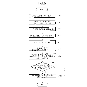
[Fig. 5] Fig. 5 is a flowchart for bad road determination.
[Fig. 6] Fig. 6 is a flowchart illustrating processing in ST06.
Description of Embodiments
[0013]
An embodiment of the invention will be described below with
reference to the attached drawings.
Example
[0014]
CA 03018944 2018-09-25
As illustrated in Fig. 1, a brake fluid pressure control device
for a vehicle appropriately controls a braking force (brake fluid
pressure) to be applied to a wheel of a vehicle. In this example,
the brake fluid pressure control device 10 is installed in a bar
handle vehicle and applied to, for example, the front wheel of a
motorcycle.
[0015]
The brake fluid pressure control device 10 for a vehicle mainly
includes a fluid pressure unit 100 in which fluid lines (brake fluid
lines) and various components are provided and a control device 200
that controls the various components in the fluid pressure unit 100.
The fluid pressure unit 100 is disposed between a master cylinder
12, which is a fluid pressure source, and a wheel brake 14.
[0016]
The fluid pressure unit 100 has an inlet control valve 15
(control valve means 15) , which is a normally open solenoid valve,
and an outlet control valve 16 (control valve means 16) , which is
a normally closed solenoid valve, provided in the fluid pressure
line from the master cylinder 12 to the wheel brake 14, a reservoir
13 in which operating fluid is stored temporarily, a check valve
18 that is provided in parallel to the inlet control valve 15 and
allows a flow only to the master cylinder 12, a pump section 21 capable
of discharging the operating fluid stored in the reservoir 13 to
the master cylinder 12, and an actuator (motor) 22 that drives this
6
CA 03018944 2018-09-25
pump section 21. The control device 200 includes a controller 30
that controls the driving of the actuator 22 and controls the opening
and closing of the inlet control valve 15 and the outlet control
valve 16 and a determining section 31 that determines whether the
state of the traveling road surface is bad.
[0017]
A wheel speed sensor 25 that detects the wheel speed of a wheel
23 is connected to the control device 200. The wheel speed is
acquired by the determining section 31 and the estimated vehicle
body speed is calculated based on the wheel speed. The signal of
bad road determination and the signals of the wheel speed and the
estimated vehicle body speed by the determining section 31 are
transmitted to the controller 30 and the controller 30 performs ABS
control and the like according to a bad road. Accordingly, control
such as ABS control can be improved.
[0018]
First, the basic operation during normal braking and the basic
operation during ABS control will be described. The brake fluid
pressure control device 10 for a vehicle has the function of
switching among a normal state during normal braking, a reduced
pressure state during ABS control, a holding state during ABS control,
and an increased pressure state during ABS control.
[0019]
During normal braking: In the normal state (that is, current
7
CA 03018944 2018-09-25
is not supplied to the inlet control valve 15 and the outlet control
valve 16) , the master cylinder 12 and the wheel brake 14 are
communicated with each other (the inlet control valve 15 is opened)
and communication between the wheel brake 14 and the reservoir 13
is interrupted (the outlet control valve 16 is closed) . When an
operating member 11 is operated, an operating fluid pressure from
the master cylinder 12 is applied to the wheel brake 14 via the inlet
control valve 15 and the wheel is braked.
[0020]
During ABS control: When the wheel is almost locked, the
control device 200 makes ABS control by performing switching among
the reduced pressure state, the holding state, and the increased
pressure state.
In the reduced pressure state during ABS control, current is
fed to the inlet control valve 15 and the outlet control valve 16
to interrupt communication between the master cylinder 12 and the
wheel brake 14 (close the inlet control valve 15) and communicate
the wheel brake 14 and the reservoir 13 with each other (open the
outlet control valve 16) . The operating fluid leading to the wheel
brake 14 is released to the reservoir 13 via the outlet control valve
16 to reduce the operating fluid pressure applied to the wheel brake
14.
[0021]
In the holding state during ABS control, current is fed only
8
CA 03018944 2018-09-25
to the inlet control valve 15 to interrupt communication between
the master cylinder 12 and the wheel brake 14 and communication
between the wheel brake 14 and the reservoir 13 (close the inlet
control valve 15 and the outlet control valve 16). The operating
fluid is confined within the flow path formed by the wheel brake
14, the inlet control valve 15, and the outlet control valve 16 to
hold the operating fluid pressure applied to the wheel brake
constant.
[0022]
In the increased pressure state during ABS control, supply
of current to the inlet control valve 15 and the outlet control valve
16 is stopped to communicate the master cylinder 12 and the wheel
brake 14 with each other (open the inlet control valve 15) and
interrupt communication between the wheel brake 14 and the reservoir
13 (close the outlet control valve 16).
[0023]
This causes the operating fluid pressure from the master
cylinder 12 to increase the fluid pressure of the wheel brake 14.
In addition, during ABS control, the control device 200 drives the
actuator 22 to operate the pump section 21. This causes the
operating fluid temporarily stored in the reservoir 13 to return
to the master cylinder 12.
[0024]
As described above, the brake fluid pressure control device
9
CA 03018944 2018-09-25
for a vehicle enables fluid pressure control of the brake fluid
pressure applied to the wheel brake 14 by repeating a control cycle
including the reduced pressure state, the holding state, and the
increased pressure state.
[0025]
Next, the structure of the determining section 31 will be
described.
As illustrated in Fig. 2, the determining section 31 includes
wheel speed acquisition means 33 that acquires a wheel speed VW
detected by the wheel speed sensor 25, estimated vehicle body speed
calculation means 34 that calculates an estimated vehicle body speed
VR based on the wheel speed VW acquired by the wheel speed acquisition
means 33, slippage amount calculation means 35 that calculates a
slippage amount SR of the wheel, and bad road determination means
36 that determines whether the state of the traveling road surface
is bad. It should be noted here that the present example uses the
value obtained by subtracting the wheel speed VW from the estimated
vehicle body speed VR as the slippage amount SR, but the invention
is not limited to the example and the value represented by (VR -
VW) /VR may be used as the slippage amount SR.
[0026]
Here, the state of a vehicle body during travel on a bad road
will be simply described. During travel on a bad road (for example,
a concavo-convex road) , a change in the wheel speed due to a slip
CA 03018944 2018-09-25
of the wheel 23 and recovery of rotation is easily caused by a change
in a wheel gripping strength and a wheel contact load. On a
concavo-convex bad road, a slip is likely to occur because the wheel
contact load is instantaneously reduced in recessed portions of the
road surface and rotation is likely to recover because the wheel
makes contact with the ground surface in convex portions of the road
surface.
[0027]
For example, a so-called overshoot (a value that is not
detected on a good road, such as noise) is likely to occur in the
wheel speed as the contact load increases when contact with a convex
portion is made and the overshoot immediately recovers.
Accordingly, the wheel speed is likely to become larger than the
vehicle body speed. Accordingly, the wheel speed changes by
instantaneously becoming larger (higher) than or smaller (lower)
than the vehicle body speed.
[0028]
Next, processing by the bad road determination means 36 will
be described with reference to Fig. 3 and Fig. 4.
First, when the wheel speed VW exceeds (also referred to below
as a lift-up) the estimated vehicle body speed VR (time ti), the
bad road determination means 36 starts measuring a lift-up time ta.
It should be noted here that the solid line in Fig. 3 indicates the
wheel speed VW and the imaginary line indicates the estimated vehicle
CA 03018944 2018-09-25
body speed VR. In addition, the bad road determination means 36
obtains a lift-up peak amount (VW1 - VR1 at time t2) as an example
of the deviation by monitoring the lift-up amount.
[0029]
Then, when the lift-up state is released (time t3), bad road
determination is performed based on the lift-up time ta and the
lift-up peak amount. Specifically, the bad road determination
threshold value TH is acquired based on the lift-up time ta and a
map MP illustrated in Fig. 4 and the lift-up peak amount is compared
with the bad road determination threshold value TH.
[0030]
Fig. 4 is a map illustrating the relationship between the
lift-up time and the bad road determination threshold value TH, and
the bad road determination threshold value TH becomes larger as the
lift-up time is larger (longer). A plurality of such maps is set
based on the magnitude of the slippage amount. In the example in
Fig. 4, a map MP1 selected when the slippage amount is equal to or
less than a predetermined value P and a map MP2 selected when the
slippage amount is more than the predetermined value P are set.
[0031]
In this example, these maps are set so that the bad road
determination threshold value TH of the map MP2 is larger than the
bad road determination threshold value TH of the map MPl. The
predetermined value Pis set by, for example, experiment, simulation,
12
CA 03018944 2018-09-25
or the like. Selection of the map MP will be described in detail
below.
When the lift-up peak amount is more than the bad road
determination threshold value TH, the bad road determination means
36 determines that the state of the traveling road surface is bad.
[0032]
It should be noted here that the state in which the wheel speed
VW is less than the estimated vehicle body speed VR (also referred
to below as low-down) is also subject to bad road determination as
in the lift-up state. When the low-down state occurs (time t3),
the bad road determination means 36 measures a low-down time tc.
In addition, the bad road determination means 36 obtains the low-down
peak amount (VR2 - VW2 at time t4) as an example of the deviation
by monitoring a low-down amount.
[0033]
Then, when the low-down state is released (t5), bad road
determination is performed based on the low-down time tc and the
low-down peak amount. Specifically, the bad road determination
threshold value TH is acquired based on the low-down time tc and
the map MP illustrated in Fig. 4 and the low-down peak amount is
compared with the bad road determination threshold value TH. When
the low-down peak amount is more than the bad road determination
threshold value TH, the bad road determination means 36 determines
that the state of the traveling road surface is bad.
13
CA 03018944 2018-09-25
[0034]
Next, a processing flow of bad road determination performed
by the above brake fluid pressure control device for a vehicle during
ABS control will be described.
As illustrated in Fig. 5, during ABS control, the wheel speed
acquisition means 33 first acquires the wheel speed VW from the wheel
speed sensor 25 in step (referred to below as ST) 01.
[0035]
In ST02, the estimated vehicle body speed calculation means
34 calculates the estimated vehicle body speed VR based on the wheel
speed VW.
In ST03, the slippage amount calculation means 35 calculates
the slippage amount SR based on the wheel speed VW and the estimated
vehicle body speed VP.
[0036]
In ST04, the bad road determination means 36 calculates the
lift-up peak amount (low-down peak amount) by monitoring the lift-up
amount (low-down amount) . In STOS, the bad road determination means
36 acquires the lift-up time (low-down time) . Although an example
of the lift-up state is described for the sake of convenience here,
similar processing can be applied during low-down and, in this case,
use of the parenthesized parameters is only required (this is also
true hereinafter) _
[0037]
14
CA 03018944 2018-09-25
In ST06, the bad road determination means 36 selects the map
MP based on the slippage amount SR. The processing in STO6 will
be described with reference to Fig. 6.
As illustrated in Fig. 6, the bad road determination means
36 starts map selection processing in ST06. The bad road
determination means 36 determines whether the slippage amount SR
is more than the predetermined value P in ST11 and, when the slippage
amount SR is more than the predetermined value P (YES in ST11),
selects the map MP2 (ST12), and returns to the processing in Fig.
5.
[0038]
In contrast, when the slippage amount SR is not more than the
predetermined value P (that is, the slippage amount SR is equal to
or less than the predetermined value P) (NO in ST11), the bad road
determination means 36 determines whether the state in which the
slippage amount SR is equal to or less than the predetermined value
P continues for a certain time or more (ST13).
When the state in which the slippage amount SR is equal to
or less than the predetermined value P continues for the certain
time or more (YES in ST13), the bad road determination means 36
selects the map MP1 (ST14) and returns to the processing in Fig.
5.
[0039]
In contrast, when the state in which the slippage amount SR
CA 03018944 2018-09-25
is equal to or less than the predetermined value P does not continue
for the certain time or more (NO in ST13) , the bad road determination
means 36 selects the same map selected last time (ST15) and returns
to the processing in Fig. 5.
[0040]
As described above, when the slippage amount SR of the wheel
is more than the predetermined value P. the bad road determination
threshold value is changed to a value larger than in the case where
the slippage amount SR is equal to or less than the predetermined
value P. This can detect the state in which the braking power
(slippage amount) is large and change the bad road determination
threshold value to an appropriate value by setting the predetermined
value P through, for example, experiment, simulation, or the like
in advance.
[0041]
In contrast, the bad road determination threshold value is
changed to a value that makes a determination as a bad road easier
as the slippage amount SR of the wheel is smaller. Since this changes
the bad road determination threshold value to a value that makes
a determination as a bad road easier as the slippage amount
corresponding to the braking power is smaller even when, for example,
an input from the brake operating member is small and the braking
power is small, bad road determination can be performed with better
precision.
16
CA 03018944 2018-09-25
[0042]
In addition, when the time period for which the slippage amount
SR of the wheel is equal to or less than the predetermined value
P continues for a certain time, the bad road determination threshold
value is changed to a value smaller than in the case where the slippage
amount SR is more than the predetermined value P. It is possible
to restore the bad road determination threshold value corresponding
to the small braking power (slippage amount SR) at an appropriate
timing. In addition, it is possible to prepare for a continuous
bad road by appropriately switching the bad road determination
threshold value between the large value and the small value.
[0043]
If such processing is performed, even when, for example, the
slippage amount becomes larger than the predetermined value P, the
map MP2 is selected, and then the slippage amount becomes equal to
or less than the predetermined value P, the map MP2 remains selected
until a certain time elapses and then the map MP1 is selected after
the state in which the slippage amount is equal to or less than the
predetermined value P continues for a certain time.
[ 0044 ]
Returning to the processing in Fig. 5, the bad road
determination means 36 acquires the bad road determination threshold
value TH based on the selected map MP and the lift-up time (low-down
time) in ST07.
17
CA 03018944 2018-09-25
In ST08, the bad road determination means 36 determines
whether the lift-up peak amount (low-down peak amount) is more than
the bad road determination threshold value TH. When the lift-up
peak amount (low-down peak amount) is more than the bad road
determination threshold value TH, the bad road determination means
36 determines that the state of the traveling road surface is bad
(ST09). When the lift-up peak amount (low-down peak amount) is not
more than the bad road determination threshold value TH, the
processing ends.
[0045]
As described above, the bad road determination means 36
determines whether the state of the traveling road surface is bad
based on the deviation (VW1 - VR1) or (VR2 - VW2) between the estimated
vehicle body speed VR and the wheel speed VW. When the deviation
(VW1 - VR1) or (VR2 - VW2) is more than the bad road determination
threshold value TH, the bad road determination means 36 determines
that the state of the traveling road surface is bad.
[0046]
The brake fluid pressure control device 10 for a vehicle
includes the wheel speed acquisition means 33, the slippage amount
calculation means 35, and the bad road determination means 36, and
the bad road determination means 36 determines whether the state
of the traveling road surface is bad using the value related to wheel
behavior calculated based on at least the wheel speed VW and the
18
CA 03018944 2018-09-25
bad road determination threshold value TH and changes the bad road
determination threshold value TH according to the slippage amount
of the wheel. This structure can appropriately set the bad road
determination threshold value TH according to the slippage amount
corresponding to the braking power and can improve the precision
of bad road determination.
[0047]
In addition, when, for example, the braking power is large,
a so-called lift-up amount and low-down amount also become large.
Accordingly, bad road determination can be performed with better
precision by setting the bad road determination threshold value TH
when the slippage amount SR of the wheel 23 is large to a value larger
than the bad road determination threshold value TH when the slippage
amount SR of the wheel is small.
[0048]
In addition, the bad road determination means 36 determines
whether the state of the traveling road surface is bad based on the
deviation (VW1-VR1) or (VR2-V1Al2) between the estimated vehicle body
speed VR and the wheel speed VW. By using the deviation (VW1-VR1)
or (VR2-VW2) between the estimated vehicle body speed VR and the
wheel speed VW as the value related to wheel behavior, it is possible
to detect reduction in gripping strength of a tire with respect to
the traveling road surface or a return tendency and noise in an output
value of the wheel speed sensor 25, which are phenomena particular
19
CA 03018944 2018-09-25
to bad roads, thereby enabling more accurate bad road determination.
This improves the precision of bad road determination and improves
fluid pressure control such as ABS.
[0049]
Although the brake fluid pressure control device for a vehicle
is provided only for the front wheel in the example, the wheel brake
fluid pressure control device may be provided only for the rear wheel
or may be provided for the front and rear wheels.
In addition, although the controller 30 and the determining
section 31 are provided as separate components in the example, the
controller 30 and the determining section 31 may be integrated and
their functions may be separated internally. In addition, although
the operating member 11 is a brake lever in the example, the operating
member 11 is not limited to a brake lever and may be a brake pedal.
[0050]
In addition, although the actuator 22 is a motor and the motor
and the pump section 21 constitute a pump 20 in the example, the
invention is not limited to the example and the actuator 22 may be
a solenoid and the pump 20 may be a solenoid pump including the
solenoid and the pump section 21.
[0051]
In addition, although the map MP1 and the map MP2 are used
in the example, the invention is not limited to the example and three
or more maps may be set in advance so that a map suited for the slippage
CA 03018944 2018-09-25
amount can be selected from the three or more maps.
In addition, although the bad road determination threshold
value TH is acquired using the map MP based on the lift-up time in
the example, a relational expression such as a function may be used
in place of the map.
Industrial Applicability
[0052]
The invention is preferable to a brake fluid pressure control
device to be mounted in a motorcycle.
Reference Signs List
[0053]
10: brake fluid pressure control device for vehicle
14: wheel brake
23: wheel
30: controller
31: determining section
33: wheel speed acquisition means
34: estimated vehicle body speed calculation means
35: slippage amount calculation means
36: bad road determination means
50: bad road (traveling road surface)
VW: wheel speed
21
CA 03018944 2018-09-25
SR: slippage amount
V1 to V4, Va to Vd: bad road determination threshold value
Tf: certain time
22