Note: Descriptions are shown in the official language in which they were submitted.
CA 03018970 2018-09-25
WO 2017/180042
PCT/SE2017/050330
1
METHOD AND APPARATUS FOR ROCK REINFORCEMENT
TECHNICAL FIELD
Present invention relates to mining industry. Particularly, the invention
relates to a
method and an apparatus at rock reinforcement, for example in conjunction with
tunnelling.
BACKGROUND
In conjunction with tunnelling or in a mine, cracks in the rock layers often
arise around a
cavity in a mountain through which for example a future tunnel will run. The
cracks
weaken the rock in the mountain, which may result in that parts of the
mountain may
collapse. Therefore actions are needed that reduce the risk for collapse. The
actions are
usually called rock reinforcement. A common method for rock reinforcement is
rock
bolting. Rock bolting means that a bolt adapted for rock bolting is fastened
in a drilled
hole by a molding agent. In this way the rock layers are bonded- and held
together so
that the risk for collapse is reduced.
W02012171056 describes an apparatus for injection of a resin in conjunction
with rock
bolting. The apparatus comprises an injector comprising a valve manifold with
shuttle
valves arranged in fluid inlets for injection of resin components. The valve
manifold
comprises also an additional inlet for a flushing fluid. All the tree inlets
end in a common
cavity that connects the inlets. The valves may be positioned in a position
that permits
injection of the components into a mixing chamber connected to the valve
manifold. The
valves may also be positioned in another position that permits supply of the
flushing fluid
through the additional inlet and the cavity for the purpose to flush the valve
manifold and
the mixing chamber. One disadvantage with the apparatus in W02012171056 is
that it
may be rests of the resin components inside the inlets when the flushing fluid
is injected
in the valve manifold, which may impair reliability of service of the
apparatus.
SUMMARY
An object of the invention is to improve the reliability of service at rock
reinforcement.
CA 03018970 2018-09-25
WO 2017/180042
PCT/SE2017/050330
2
According to one aspect of the invention, the object is achieved by a method
at rock
reinforcement comprising the steps: to inject a first component and a second
component
through a first channel and a second channel respectively into a rock hole,
wherein the
first component and the second component are adapted for rock reinforcement
and to
inject a blocking agent through a third channel into at least said second
channel, wherein
said blocking agent provides a barrier in at least said second channel.
Because, the method comprises the step to inject the blocking agent through
the third
channel into at least the second channel, the blocking agent can extrude at
least the
second component from at least the second channel and can replace at least the
second
component inside at least the second channel where the blocking agent has been
injected. In this way, an area in at least the second channel is achieved
where at least
the second component has been replaced by blocking agent. Further, because the
blocking agent provides said barrier in at least the second channel, at least
the second
channel is blocked from coming in contact with for example moisture and/or the
first
component in at least the second channel where the blocking agent has been
injected.
In this way, the second component and for example moisture and/or the first
component
are held separated from each other in at least the second channel thanks to
the blocking
agent which constitutes said barrier. Thereby, at least the second channel is
protected
from for example coatings on at least the second channel, which coatings may
be
created when the second component cures upon contact with for example moisture
and/or upon contact with the first component. As a result of thereof, the risk
for a stop in
at least second channel, i.e. the risk for that the second channel will be
filled with
coatings is reduced. Thereby, the risk for interruption during the work with
rock
.. reinforcement is decreased, i.e. reliability of a process of rock
reinforcement is improved.
Consequently, a method at rock reinforcement is provided that achieves the
above
mentioned object.
.. According to some embodiments the method comprises the step: to provide,
for example
to drill, the rock hole before the step: to inject the first component and the
second
component through the first channel, respectively through the second channel
into a
rock hole is performed.
CA 03018970 2018-09-25
WO 2017/180042
PCT/SE2017/050330
3
The method may comprise the step: to place a rock bolt adapted for rock
reinforcement
in the rock hole. This may permit that more efficient rock reinforcement is
achieved than
if rock reinforcement is performed without the rock bolt placed in the rock
hole.
The first component and the second component may be injected through the rock
bolt. In
this way there is no need of removing the rock bolt from the rock hole.
Thereby an
efficient method at rock reinforcement is achieved because fewer steps are
needed for
injecting the first component and the second component into the rock hole,
comparing to
when removing of the rock bolt from the rock hole is needed for injection of
the first
component and the second component. Further advantageously, the first
component
and the second component may be guided into the rock hole through the rock
bolt, i.e.
along the interior of the rock bolt all the way into the rock hole. Thereby,
an improved
rock reinforcement is achieved because the first component and the second
component
may be sent all the way into the rock hole through the rock bolt.
The rock bolt may be a self-drilling bolt. Thereby, the rock bolt may be
drilled into the
rock hole and at the same time may be placed in the rock hole during the time
for
achieving the rock hole. This simplifies and makes the process of rock
reinforcement
more efficient because fewer steps are needed to achieve the rock hole and to
place the
.. rock bolt in the rock hole comparing to firstly drilling the rock hole, for
example with a
drill, and later to place a non-self-drilling rock bolt in the rock hole.
According to some embodiments the step: to inject a first component and a
second
component through a first channel and a second channel respectively into a
rock hole,
comprises injecting the first component and the second component at least
partly
simultaneously into the rock hole. Because the first component and the second
component may be injected partly simultaneously into the rock hole, i.e.
substantially at
the same time, the first component and the second component may get into the
rock
hole substantially simultaneously and substantially without any time delay.
This permits
that the first component and the second component may be mixed with each other
partly
substantially during that the first component and the second component are
injected into
the rock hole. This may improve mixing of the first component and the second
component. Thus, with advantage an improved method at rock reinforcement is
obtained.
CA 03018970 2018-09-25
WO 2017/180042
PCT/SE2017/050330
4
The method may also comprise the step: to inject a flushing agent into at
least the first
channel, wherein the blocking agent is adapted to prevent the flushing agent
from
coming into contact with the second component at the injection of the flushing
agent.
Because the method may comprise the step to inject the flushing agent into at
least the
first channel, at least the first channel may be rinsed clean and possible
remains of at
least the first component may be carted away, i.e. removed from at least the
first channel
in an efficient manner. Further, because the blocking agent is adapted to
prevent the
flushing agent from coming into contact with the second component at the
injection of
the flushing agent, at least the second component may be prevented from coming
into
contact with the flushing agent in at least the second channel where the
blocking agent
has been injected. In this way, the second component and the flushing agent
are held
separated from each other in at least the second channel thanks to the
blocking agent at
injection of the flushing agent. Advantageously, crystallization of the second
component
in at least the second channel is prevented, which otherwise occurs when the
flushing
agent comes into contact with the second agent. Thereby, the risk that at
least the
second channel will be blocked, i.e. will be filled with crystals of the
second component is
decreased. As a result thereof the risk for interruptions during work with
rock
reinforcement is reduced, i.e. reliability at rock reinforcement is improved.
According to some embodiments the step: to inject the blocking agent through
the third
channel into at least the second channel is performed after the step to inject
the first
component and the second component through the first channel and the second
channel
respectively into a rock hole. As result of this, the blocking agent may
extrude at least
the second component and replace at least the second component in at least the
second
channel where the blocking agent has been injected. Thereby, a region in at
least the
second channel is obtained where at least the second component has been
replaced by
the blocking agent. Furthermore, or alternatively, according to the
embodiments the step:
to inject the flushing agent into at least the first channel is performed
after the step: to
inject the blocking agent through the third channel into at least the second
channel.
Thus, at least the first channel may be flushed by the flushing agent after
that the first
component and the second component have been injected into the rock hole. One
CA 03018970 2018-09-25
WO 2017/180042
PCT/SE2017/050330
advantage with this is that it may occur without risks that the flushing agent
comes in
contact with the other component in at least the second channel, which may
cause a
stop in the second channel. Thereby, with advantage an improved method at rock
reinforcement is obtained that permits an effective cleaning of at least the
first channel
5 after injection of the first component and the second component into the
rock hole.
Further, the risk for a stop in at least second channel is decreased at
flushing of at least
the first channel. Thereby, the risk for interruption during the work with
rock
reinforcement is also decreased, which improves the reliability at rock
reinforcement.
The first component may be a hardener and the second component may be a resin.
In a
known manner a mixture of the first component and the second component may be
used
to bond and to reinforce the rock.
According to a further aspect the object mentioned above is achieved by an
apparatus at
.. rock reinforcement comprising: a first channel adapted for injection of a
first component
into a rock hole and a second channel adapted for injection of a second
component into
the rock hole, wherein the first component and the second component are
adapted for
rock reinforcement. Further, the apparatus comprises a third channel for
injection of a
blocking agent into at least the second channel, wherein the third channel is
directly
connected to at least the second channel.
Because, the apparatus comprises the third channel for injection of the
blocking agent
into at least the second channel, the blocking agent can extrude at least the
second
component from at least the second channel and can replace at least the second
component inside at least the second channel where the blocking agent has been
injected. In this way, an area in at least the second channel is achieved
where at least
the second component has been replaced by the blocking agent and where at
least the
second component is blocked from coming in contact with for example moisture
and/or
the first component in at least the second channel where the blocking agent
has been
.. injected. In this way, the second component and for example moisture and/or
the first
component are held separated from each other in at least the second channel
thanks to
the blocking agent which constitutes said barrier. Thereby, at least the
second channel is
protected from for example coatings on at least the second channel, which
coatings may
be created when the second component cures upon contact with for example
moisture
CA 03018970 2018-09-25
WO 2017/180042
PCT/SE2017/050330
6
and/or upon contact with the first component. As a result of thereof, the risk
for a stop in
at least second channel, i.e. the risk for that the second channel will be
filled with
coatings is reduced. Thereby, the risk for interruption during the work with
rock
reinforcement is decreased, i.e. reliability of a process of rock
reinforcement is improved.
Further, because the third channel is directly connected to at least the
second channel,
the blocking agent may be injected directly to at least the second channel,
i.e. without
need of any detours. With advantage, an apparatus at rock reinforcement is
achieved
that permits an efficient injection of the blocking agent into at least the
second channel.
Consequently, an apparatus at rock reinforcement is provided that improves the
reliability during rock reinforcement and thereby the above mentioned object
is obtained.
The first channel may be arranged to receive a flushing agent. Thereby, at
least the first
channel may be rinsed clean and possible remains of at least the first
component may
be carted away, i.e. may be removed from at least the first channel in an
efficient
manner by that the flushing agent can be sent through the first channel.
Thereby, a
compact apparatus at rock reinforcement is provided which permits flushing of
at least
the first channel.
According to some embodiments, the second channel comprises a valve-piston
arranged to be positioned in at least a first position and a second position.
In this way
the valve-piston may change position between at least the first position and
the second
position. In the first position, the valve-piston may be arranged to permit
injection of the
second component into the rock hole, wherein in the second position the valve-
piston
may be arranged to prevent injection of the second component in the rock hole
and to
permit injection of the blocking agent into at least the second channel.
Consequently, the
second component may be sent into the rock hole in a simple way by that the
valve-
piston is positioned in the first position. Further, injection of the second
component into
the rock hole may be prevented in a simple way by that the valve-piston is
positioned in
the second position while injection of the blocking agent into at least the
second channel
may be permitted when the valve-piston is positioned in the second position.
Thereby,
an efficient apparatus at rock reinforcement is provided that in a simple and
efficient way
CA 03018970 2018-09-25
WO 2017/180042
PCT/SE2017/050330
7
can control flow of the second component and of the blocking agent by a simple
conversion of the valve-piston.
BRIEF DESCRIPTION OF THE DRAWINGS
The further aspects of the subject matter, including their particular features
and
advantages, will be readily understood from the following detailed description
of one or
several embodiments provided with reference to the accompanying drawings,
where:
Fig. 1 is a side-view of an exemplified apparatus at rock reinforcement at a
rock hole
with a rock bolt, shown in cross-section,
Fig. 2 is a flow-chart showing a method at rock reinforcement,
Fig. 3 is a perspective-view of the apparatus according to Fig. 1 and
Fig. 4 is another perspective-view of the apparatus according to Fig. 1 and
Fig. 3.
DETAILED DESCRIPTION
The embodiments herein will now be described in more detail with reference to
the
accompanying drawings, in which example embodiments are shown. Disclosed
features
of example embodiments may be combined. Like numbers refer to like elements
throughout.
Fig. 1 illustrates an exemplified embodiment of an apparatus 1 at rock
reinforcement or
sometimes called rock-bolting. The apparatus 1 has been connected to a rock
bolt 11
through a mixer 2and a connection means 4. Fig. 1 illustrates as well a cross
section
through a rock hole 9 in a mountain where the rock bolt 11 has been placed in
the rock
.. hole 9.
When a rock need to be reinforced, the rock hole 9 is drilled in the rock.
This is made by
using of a drill or by using a self-drilling bolt. The rock bolt 9 in Fig. 1
illustrates a self-
drilling bolt comprising a drilling bit 30. A self-drilling bolt is placed in
the rock hole while
and simultaneously the rock hole is created by the self-drilling bolt. Self-
drilling bolts are
known in the art and therefor are not described herein in details.
To anchor the rock bolt 11 in the rock hole 9 and to achieve rock
reinforcement, a
molding agent as for example a mixture of components, is injected in the rock
hole. The
CA 03018970 2018-09-25
WO 2017/180042
PCT/SE2017/050330
8
mixture of components is injected by the apparatus 1. The mixture of
components is
solidifying or hardening inside the rock hole and around the rock bolt 11 and
in this way
the rock bolt 11 is anchored or is fastened inside the rock hole. As a result
of this the
rock at and around the rock hole 9 is reinforced. According to the embodiment
illustrated
in Fig 1, the rock bolt 11 is hollow, which permits the mixture of components
may be
injected through the rock bolt 11 and out through the drilling bit 30 into the
rock hole 9.
Fig. 2 shows an exemplified method 100 at rock reinforcement. The method 100
may for
example be implemented by a control unit (not shown).
The method 100 comprises: to inject 101 a first component and a second
component
through a first channel and a second channel respectively into a rock hole,
wherein the
first component and the second component are adapted for rock reinforcement.
The step
to inject 101 the first component and the second component through the first
channel
and the second channel respectively into a rock hole may comprise to inject he
first
component and the second component at least partly simultaneously into the
rock hole.
Further the method 100 comprises to inject 103 a blocking agent through a
third channel
into at least the second channel, wherein the blocking agent provides a
barrier in at least
the second channel.
The method 100 may also comprise to inject 103 a flushing agent into at least
the first
channel.
Further, the step to inject 103 the blocking agent through the third channel
into at least
the second channel may be performed after the step to inject 101 the first
component
and the second component through the first channel and the second channel
respectively into a rock hole and/or wherein the step to inject 103 the
flushing agent into
at least the first channel may be performed after the step to inject 105 the
blocking agent
through the third channel into at least the second channel.
The method 100 may also comprise the step to inject the blocking agent into
the first
channel.
CA 03018970 2018-09-25
WO 2017/180042
PCT/SE2017/050330
9
According to some embodiments, the method 100 may comprise to provide 107, for
example to drill, the rock hole before the step to inject 101 the first
component and the
second component through the first channel and the second channel respectively
into
the rock hole is performed. The method 100 may further comprise to place 109
the rock
bolt, adapted for rock reinforcement, in the rock hole.
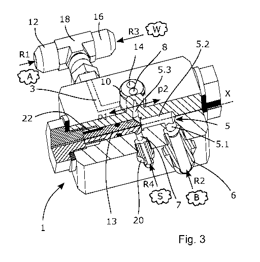
Fig. 3 illustrates the apparatus 1 in Fig. 1. The apparatus 1 comprises a
first channel 3
adapted for injection of first component A into a rock hole, and a second
channel 5
adapted for injection of second component B into the rock hole. Thus, in this
example,
the earlier mentioned mixture of components comprises of the first and the
second
components A, B. According to the embodiment illustrated in Fig. 3, the second
channel
5 comprises three sub-channels named a first sub-channel 5.1, a second sub-
channel
5.2 and a third sub-channel 5.3. The first sub-channel 5.1 in Fig. 3 is
arranged
substantially radially, i.e. substantially perpendicular in relation to an
axis X through the
apparatus 1. The second sub-channel 5.2 is arranged substantially along the
axis X and
substantially in the middle of the apparatus 1. The third sub-channel 5.3
extends along a
direction substantially perpendicular in relation to the axis X and
substantially
perpendicular in relation to the first sub-channel 5.1. The first sub-channel
5.1 extends
also from a second channel nozzle 6 arranged at a periphery of the apparatus 1
towards
the second sub-channel 5.2 arranged substantially in the middle of the
apparatus 1 and
the third sub-channel 5.3 extends from the second sub-channel 5.2 and ends
through a
second opening 8 of an outlet nozzle 10.
The directions "towards" and "from" refer here directions in relation to
injection direction
R2 of the second component B at the inlet to the second channel nozzle 6 and
in relation
to the axis X. The second channel nozzle 6 is arranged to receive a second
hose (not
shown) for supplying of the second component B into the apparatus I. The tree
sub-
channels 5.1, 5.2 and 5.3 are interconnected with each other and together form
the
second channel 5.
The first channel 3 (not shown in details in Fig. 3) may be arranged in a
similar manner
as the second channel 5. Thereby, the first component A may be injected, for
example in
the injection direction R1 of the first component A, through a first channel
nozzle 12 into
the apparatus 1 and further out through a first opening 14 of the outlet
nozzle 10.
CA 03018970 2018-09-25
WO 2017/180042
PCT/SE2017/050330
The first channel nozzle 12 is arranged to receive a first hose (not shown)
for supplying
of the first component A to the apparatus 1. In the similar way as the second
component
B above refer directions "in" and "out" directions in relation to the
injection direction R1 of
the first component A at the inlet to the first channel nozzle 12.
5
The first channel 3 and the second channel 5 are separated from each other
that the first
component A and the second component B do not come in contact with each other
inside the apparatus I. The first channel 3 and the second channel 5 may be
achieved
by for example molding of the apparatus 1 in a form. The form is then designed
so that
10 two separate channels are obtained inside the apparatus 1 after a
molding process. The
first channel 3 and the second channel 5 may also be achieved by processing as
for
example drilling, milling or similar.
The outlet nozzle 10 may be arranged to receive a mixer (not shown in Fig. 3)
adapted
to mix the first component A and the second component B with each other.
The first component A and the second component B are adapted for rock
reinforcement,
i.e. they are developed for example this purpose. The first component A may
contain a
hardener as for example sodium silicate, an alcohol, a polyol or similar or a
combination
thereof. The second component B may contain a resin as for example methylene
diphenyl isocyanate (MDI) or similar. The first component A and the second
component
B are intended to be mixed with each other at injection of the first component
and the
second component A, B into the rock hole. Mixing of the first component A and
the
second component B may preferably be done in a mixer (not shown). The mixer
may
then be connected to the outlet nozzle 10. When the components A, B are mixed
a
reaction in the resin starts that is trigged by the hardener and that results
in that
crosslinks in the resin are created. Said mixture of the first component A and
the second
component B may be guided, or brought, further from the mixer into the rock
hole where
the mixture is and thereby a rock bolt is anchored inside the rock hole to
reinforce the
rock around the rock hole.
As illustrated in Fig. 3, the first channel 3 may be arranged to receive a
flushing agent W,
for example in a direction R3 of the flushing agent. This, through a flushing
nozzle 16.
According to the embodiment illustrated in Fig. 3, the first channel nozzle 12
and the
CA 03018970 2018-09-25
WO 2017/180042
PCT/SE2017/050330
11
flushing nozzle 16 are arranged at a T-connection 18 connected to the first
channel 3.
The flushing nozzle 16 is arranged to receive a flushing hose (not shown) for
supplying
of the flushing agent W into the apparatus 1. The T-connection 18 comprises a
valve
(not shown) for controlling the flows of the first component A and of the
flushing agent W
into the first channel 3. The valve is arranged so that when injecting the
first component
A inflow of the flushing agent W into the first channel 3 is prevented and is
arranged so
that when injecting of the flushing agent W the inflow of the first component
A into the
first channel 3 is prevented.
The flushing agent W may be water, oil or similar.
The apparatus 1 comprises also a third channel 7 for injecting of a blocking
agent S into
at least the second channel 5. According to the embodiment illustrated in Fig.
3, the third
channel 7 is arranged substantially parallel with the second channel 5 and is
direct
connected to the second sub-channel 5.2 of the second channel 5. The third
channel 7
is connected to a third channel nozzle 20, which third channel nozzle 20 is
adapted to
receive a third hose (not shown) for supplying, for example in an blocking
agent S
injection direction R4, of the blocking agent S into the apparatus 1.
The apparatus 1 may comprise a fourth channel (not shown) for injecting of the
blocking
agent S into the first channel 3. The fourth channel may be arranged in a
similar way as
the third channel 7 described above.
The blocking agent S is an agent with chemical characteristics that make that
the
blocking agent S does not mix with any of the first component A, the second
component
B or with the flushing agent W. Further, the blocking agent may have
protecting
characteristics against wear inside the apparatus 1. The blocking agent S may
be fat
and viscous agent as for example fat, silicone or similar.
According to the embodiment illustrated in Fig. 3, the second channel 5
comprises a
valve-piston 13 movable arranged in the second channel 5 so that the valve-
piston 13
may be positioned in a first position p1 and a second position p2. The valve
piston 13
may form a part of a needle valve. Thus, the needle valve comprises the valve-
piston 13,
for example in a form of a needle, piston or similar. The needle valve may be
biased in
CA 03018970 2018-09-25
WO 2017/180042
PCT/SE2017/050330
12
the second position by a spring 22 in a known manner. Also other types of
valves than
needle valve may be used in the apparatus 1. For example, a ball valve, cone
valve or
similar may be used. The needle valve or if other type of valve, may be
controlled
hydraulically or electrically.
The valve-piston 13 in Fig. 3 is illustrated in the first position pl. In the
first position p1,
the valve-piston 13 is arranged to permit injection of the second component B
into the
rock hole. When the second component B is pumped into the apparatus 1 through
the
second channel nozzle 6 and by a pump (not shown) a pressure in the second
channel
is created that cause the valve-piston 13 to move to the first position p1.
The spring 22 is
adapted to act on the valve-piston 13 with a spring force that is less than a
pressure
force acting on the valve-piston13 by the pressure in the second channel 5
caused by
the second component B when the second component B is injected into the second
channel 5. As illustrated in Fig. 3, in the first position of the valve-piston
13, the inlet to
the third sub-channel 5.3 is open so that the second component B may flow into
the third
sub-channel 5.3 and further out through the second opening 8.
According to the embodiment illustrated in Fig. 3, the valve-piston 13 is
arranged to
permit injection of the blocking agent S into the second channel 5 when the
valve-piston
13 is in the first position pl. However, a control unit (not shown) is
connected to the
apparatus 1 and is arranged to stop supply of the blocking agent S into the
second
channel Sin the first position p1 of the valve-piston 13.
Fig. 4 illustrates the apparatus 1 in Fig. 3. In Fig. 4, the valve-piston 13
is shown in the
second position p2. In the second position p2, the valve-piston 13 is arranged
to prevent
injection of the second component B into the rock hole and to permit injection
of the
blocking agent S into at least the second channel 5. When earlier mentioned
pump (not
shown) for pumping of the second component B stops to work, the pressure in
the
second channel 5 decreases. This permits that the spring force of the spring
22 can
overcome the inertia of the second component B in the second channel 5 and to
move
the valve-piston 13 to the second position p2. As illustrated in Fig. 4, the
valve-piston 13
has been moved to the second position p2 by the spring 22, thereby has revert
to its
biased position. The valve-piston 13 comprises a surface 24 adapted to join
tight in
contact with an edge surface 26 of the second sub-channel 5.2 at the inlet to
the third
CA 03018970 2018-09-25
WO 2017/180042
PCT/SE2017/050330
13
sub-channel 5.3 and at the transition area between the second sub-channel 5.2
and the
third sub-channel 5.3 in the second position p2 of the valve-piston 13. In the
second
position p2 the spring 22 may act on the valve-piston 13 with a spring force
that permits
a tight connection between the surface 24 and the edge surface 26. Thereby,
the inlet to
the third sun-channel 5.3 may be blocked for the second component B in the
second
position p2 of the valve-piston 13, which may prevent injection of the second
component
B into the third sub-channel 5.3.
When the valve-piston 13 is in the second position p2, injection of the
blocking agent S
into at least the second channel 5 is permitted. As illustrated in Fig 4, the
valve-piston
13 may comprise a channel 28 arranged around the valve-piston 13, for example
in its
surface along a cross section of the valve-piston 13. In the second position
p2, the
channel 28 is arranged to create a connection channel between the third
channel 7 and
the third sub-channel 5.3 of the second channel 5. Thereby, injection of the
blocking
agent S into the third sub-channel 5.3 is permitted. When the blocking agent S
is
injected into the third sub-channel 5.3, the second component B is extruded
from the
third sub-channel 5.3 through the second opening 8. Thereby, the sub-channel
5.3 is
filled with the blocking agent S, which protects the sub-channel 5.3 from
other
substances to flow into the sub-channel 5.3.
The third channel 7 may be arranged so that the third channel 7 is connected
directly to
the third sub-channel 5.3. According to such embodiment, the valve 13 may be
arranged
without a channel.
As described, above the apparatus 1 may comprise the fourth channel (not
shown) for
injecting of the blocking agent S into the first channel. The fourth channel
may be
connected to the first channel in similar way arranged in a similar way as the
third
channel 7 is connected to the second channel 5 as above.
Thus, in the second position p2, the flushing agent W may be injected into the
rock hole
without risks that the flushing agent W comes in contact with the second
component B
inside the second channel 5 of the apparatus 1. Consequently, with advantage
crystallization of the second component B in at least the second channel 5 is
prevented,
which otherwise occurs when the flushing agent S comes in contact with the
second
CA 03018970 2018-09-25
WO 2017/180042
PCT/SE2017/050330
14
component B. Thereby, the risk that at least the second channel will be
blocked, i.e. will
be filled with crystals of the second component is decreased. As a result
thereof the risk
for interruptions during work with rock reinforcement is reduced, i.e.
reliability at rock
reinforcement is improved.
10
20