Note: Descriptions are shown in the official language in which they were submitted.
CA 03019636 2018-10-01
WO 2017/176195
PCT/SE2017/050317
A DRAIN PIPE INSERT ARRANGEMENT AND A SYSTEM OF SUCH
ARRANGEMENTS
TECHNICAL FIELD
The present invention relates to a drain insert arrangement for a building
having a drain
pipe.
BACKGROUND
The emergence of damage by water in modern buildings is an increasing problem,
especially
since many household appliances uses water to perform their tasks.
Traditionally, an insert
has been placed on the floor underneath refrigerators, dishwashers and washing
machines
to collect leakage and make its presence known by directing the water to the
front of the
appliance where it can be spotted.
When planning and building new houses, it is desirable to include a floor
drain through
which leakage can be evacuated in any rooms that have appliances that use
water. Creating
the drain can however be a cumbersome process involving moulding and to
achieve a drain
that lies flush with the floor requires knowledge of the type and thickness of
floor that is to
be used in the room, something that is not always known at early stages of
building.
Overflow drains are known from WO 02/06595 and WO 97/36064, among other, but
do now
show constructions that could be mounted in a quick and secure manner, while
also being
cost efficient and allowing a large flow of water during a short time. There
is therefore a
need for improved drain arrangements for use in modern buildings.
SUMMARY OF THE INVENTION
The object of the present invention is to eliminate or at least to minimize
the problems
mentioned above. This is achieved through a drain insert arrangement according
to the
appended independent claims. Thanks to the connector, a drain insert
arrangement can be
created from a drain pipe of a standard model, even if the drain pipe extends
from the floor
in a direction that is not perpendicular. The deformable element allows for an
angling or
tilting of the connector in relation to the drain pipe that still results in a
convenient and
reliable drain insert arrangement, and also allows for a mounting of the same
connector in
drain pipes of different dimensions. The locking mechanism which is configured
for
cooperating with a corresponding locking mechanism in a valve which can be
mounted in the
connector and thereby lock the valve in place inside the insert of the
connector provides the
advantage that a valve can be held in the intended place and a loosening of
the valve, for
instance by water rising in the drain pipe, can be avoided.
According to an aspect of the invention, the deformable element is in the form
of drain
flanges that are arranged around the entire circumference of the insert.
Thereby, the
position and inclination of the connector can be adjusted and the connector
held securely in
place regardless of the orientation of the connector in the drain pipe.
According to a further
1
CA 03019636 2018-10-01
WO 2017/176195
PCT/SE2017/050317
aspect of the invention, the deformable element is the drain pipe insert
itself, preferably
having an upper diameter that is smaller than a lower diameter, so that the
drain pipe insert
at the lower end can be deformed by the drain pipe.
According to another aspect of the invention, the connector further comprises
at least one
holder arranged on an inner circumference of the insert, said holder being
deformable.
Thereby, another component such as a valve can be held inside the insert of
the connector
in a similar way to the way that the connector itself is held in the drain
pipe. Preferably, the
connector comprises a plurality of holders arranged symmetrically on the inner
circumference of the insert. This gives the same advantages as the
distribution of the drain
flanges on the outside of the connector, as described above, and also allows
for the creation
of an outer drain passage between a valve and the connector.
According to a further aspect of the invention, the connector comprises at
least one rib that
extends radially on an upper side of the sealing flange. Thereby, an improved
drainage of
water from the floor surrounding the drain insert arrangement can be achieved,
thanks to
capillary forces that arise in connection to a side of the rib and a surface
of the sealing flange
to guide the water towards the insert.
According to yet another aspect of the invention, an adhesive is arranged on a
lower side of
the sealing flange for creating a seal between the sealing flange and a floor.
Thereby, water
can be prevented from entering a space between the connector and the floor or
drain pipe,
so that damages because of the water can be avoided.
According to a further aspect of the invention, a valve is provided for
guiding a fluid into the
drain pipe, said valve having a central passage and being mounted in the
insert. Thereby, the
connector and the valve cooperate to evacuate water into the drain pipe in an
efficient and
reliable way.
According to yet another aspect of the invention, the valve is held in the
connector by the
holder in such a way that an outer drain passage is created between an outer
circumference
of the valve and the inner circumference of the connector. Thereby, an
additional passage
for an improved evacuation of water can be achieved, and preferably at least
one of the
outer drain passage and the inner drain passage comprise a valve that prevents
water from
rising from the drain pipe and back up onto the floor.
According to yet another aspect of the invention, the drain insert arrangement
also
comprises at least one sensor for detecting a fluid at the drain insert
arrangement, said
sensor being operatively connected to an alarm. Thereby, the presence of water
at the drain
insert arrangement can be detected and signaled to notify inhabitants of the
building that a
leakage has arisen and must be taken care of.
Many additional benefits and advantages of the invention will become readily
apparent to
the person skilled in the art in view of the detailed description below.
2
CA 03019636 2018-10-01
WO 2017/176195
PCT/SE2017/050317
DRAWINGS
The invention will now be described in more detail with reference to the
appended
drawings, wherein
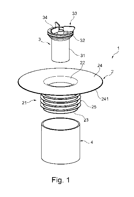
Fig. 1 discloses an exploded view of a drain insert arrangement
according to a
preferred embodiment of the invention;
Fig. 2 discloses an exploded view of the drain insert arrangement of
Fig. 1 with a
connector of the drain insert arrangement mounted in a floor;
Fig. 3a discloses a perspective view of the connector of the drain
insert arrangement
of Fig. 1;
Fig. 3b discloses the connector in a plane view from above;
Fig. 3c discloses a cross-sectional view from the side of the drain
insert arrangement
mounted in a drain pipe;
Fig. 4a discloses an exploded view of a second embodiment of the drain
insert
arrangement of the invention;
Fig. 4b discloses a cross-sectional view from the side of the second
embodiment;
Fig. 5a discloses an exploded view of a third embodiment of the drain
insert
arrangement of the invention;
Fig. 5b discloses a side view of the third embodiment;
Fig. 5c discloses a perspective view of an alternative embodiment of
the drain of the
third embodiment; and
Fig. 5d discloses a perspective view of the third embodiment; and
Fig. 6 discloses the connector of the invention having ribs and a
locking mechanism.
DETAILED DESCRIPTION
Fig. 1 discloses a drain insert arrangement 1 according to a preferred
embodiment of the
present invention, with a connector 2 and a valve 3 that are intended to be
mounted
together in a drain pipe 4. The connector 2 comprises a drain pipe insert 21
that is hollow
and has a central through hole extending from an upper end 22 to a lower end
23. The insert
21 has a deformable element, in this embodiment in the form of a plurality of
drain flanges
25 mounted around its outer circumference, and a sealing flange 24 attached to
the upper
end 22 and extending radially, i.e. in a plane that is perpendicular to the
circumference of
the drain pipe insert 21.
3
CA 03019636 2018-10-01
WO 2017/176195
PCT/SE2017/050317
When building a new house, drain pipes are generally put in place before a
floor is created,
generally by pouring concrete or the like into a space where the floor of the
room is
intended to be. The drain pipes 4 extend upwards from this floor level and to
complete the
floor itself a separate layer such as a wooden or plastic floor is placed on
top of the concrete.
Afterwards, the drain pipe 4 can be cut to make its upper end lie flush with
the floor and
thereby make it ready for mounting of the drain insert arrangement.
To mount the drain insert arrangement 1, the lower end 23 of the connector 2
is inserted
into the drain pipe 4 so that the drain flanges 25 are pressed against an
inner circumference
of the drain pipe 4 and are deformed between the insert 21 and the drain pipe
4. It is thus
.. advantageous that the drain flanges 25 are flexible and deformable, since
this allows for a
mounting of the connector 2 into drain pipes 4 of different dimensions, and
since they
thereby create a high level of friction if tried to pull out of the pipe 4
again. At the same
time, the connector 2 can be adjusted by tilting or angling in relation to the
drain pipe 4 and
a surrounding floor. This is advantageous, since it is often a problem that
the drain pipe 4
does not extend perpendicular to the floor but at an angle that is not
possible to predict. By
thus tilting the connector 2 when the lower end 23 has been inserted into the
drain pipe 4,
the connector 2 can create a watertight and reliable passage from the floor
into the drain
pipe 4 and maintain the sealing flange 24 essentially horizontal on the floor.
The sealing
flange 24 is pressed down onto the floor and preferably also comprises an
adhesive on a
lower side 241 of the sealing flange 24 that can provide a secure and
waterproof connection
between the connector 2 and the floor and prevent water from penetrating
underneath the
sealing flange 24.
After the connector 2 has been mounted into the drain pipe 4 and on the floor,
a valve 3 is
inserted into the through hole in the drain pipe insert 21 and mounted there
to provide a
drain and/or well for overflowing water.
The valve 3 can vary in appearance and components, as will be described below
with
reference to the other embodiments. It is to be noted, however, that elements
of the
different embodiments can freely be combined unless it is explicitly stated
that this is not
possible.
The valve 3 discloses in the embodiment of Fig. 1 comprises a pipe 31 and a
gasket 32 that
prevents water from entering between the connector and the outside of the
valve 3. On an
upper end 33 of the valve 3 is a strainer 34 with at least one opening to
guide water into the
pipe 31.
Fig. 2 discloses the connector 2 mounted on a floor through which extends a
pair of drain
pipes 4, and on which is arranged a liquid-proof insert 5 on which water
leaking from an
appliance can be collected to protect the floor.
Fig. 3a discloses the connector 2 in more detail, where holders 26, also
called deformable
holding devices 26, are shown inside the drain pipe insert 21. At least one
holder 26,
4
CA 03019636 2018-10-01
WO 2017/176195
PCT/SE2017/050317
preferably a plurality of holders 26 are arranged on an inner surface of the
drain pipe insert
21 and in this embodiment of the invention they are arranged along a length of
the insert
21. The holders 26 can be symmetrically distributed over the inner
circumference of the
drain pipe insert 21 and they serve to hold the valve 3 in place, preferably
by deforming
when the valve 3 is inserted to create a holding force and to be able to
receive different
embodiments of the valve 3 without requiring modifications to the connector 2.
Fig. 3b
discloses the connector 2 from above, with the holders 26 visible, and Fig. 3c
discloses the
mounted drain insert arrangement 1 from the side in a drain pipe 4.
Fig. 4a-4b discloses a second embodiment having essentially the same connector
2 as the
preferred embodiment described above, but with a second type of valve 3'. In
this
embodiment, the valve 3' comprises deformable holding devices in the form of
holder
flanges 31' that provide the same holding function as the holders 26 described
above, and
that may be changed for such holders 26 without requiring any other
modifications. The
valve 3' also has a bottom section 32' that may comprise either a water trap
or a valve to
prevent undesired odours or water to rise up through the drain 4 when the
drain insert
arrangement 1 is mounted. The connector 2 also comprises a locking mechanism
27 (see
below) that may cooperate with the valve 3 to hold it in place. The deformable
element of
the connector 2 is in this embodiment the drain pipe insert 21 itself,
preferably having an
upper diameter d1 at the upper end and a lower diameter d2 in the lower end,
where the
lower diameter d2 is larger than the upper diameter d1. This serves the same
purpose as the
drain flanges 25 described above, but allows for a mounting by a deforming of
the drain pipe
insert 21 itself upon insertion into the drain pipe 4.
Fig. 5a-5b disclose a third embodiment with the same connector 2 as described
above but
with a third type of valve 3". This third valve 3" comprises a valve 32" with
a sealing
membrane that acts as a seal to prevent water from rising up in the pipe 4 and
that also
having a drain holder 33" that holds a lower part of the third valve 3"
against the inner
circumference of the connector 2. The connector 2 also has the holders 26 that
serve to hold
the valve 3 in place, and the third valve 3" has a strainer 34" with holes
through which
overflow water can flow into an outer passage 38" created between an outer
circumference
of the valve 3" and the inner circumference of the drain pipe insert 21 of the
connector. The
valve 3" also has a central opening 35" that may receive larger quantities of
water, or that
may alternatively be connected to a pipe or tube from a kitchen appliance or a
sink or similar
that empties fluid into the drain pipe 4 via the valve 3" and connector 2.
Fig. 5a-b also disclose the locking mechanism 27, 37" that in this embodiment
is able to
fixate the valve 3" in relation to the connector 2 by inserting the valve 3"
into the connector
2 and rotating the valve 3" so that the locking mechanism 37" on the valve 3",
in this
drawing shown as openings in a flange, interact with the locking mechanism 27
of the
connector 2 and locks the valve 3" and connector 2 in relation to each other.
Many other
locking mechanisms may of course be used with the invention, and with this and
the other
5
CA 03019636 2018-10-01
WO 2017/176195
PCT/SE2017/050317
embodiments, such as for instance by fitting a part of the flange into an
opening and
pressing it into place to hold it securely, by bending a part of the flange or
other part of the
drain to insert it into an opening that retain said part, or in any other
suitable way. The
locking mechanism of this embodiment is shown in its mounted stage by Fig. 5d.
Since the
locking mechanism 37" on the valve 3 comprises a plurality of openings, each
of which being
adapted to interact with the locking mechanism 27 on the connector 2, water
may flow into
the valve 3 also through these openings to allow for a more efficient draining
of water.
Fig. 5c discloses another version of the third valve 3" of the third
embodiment of Fig. 5a-5b,
differing from the one described immediately above by the drain being arranged
excentrically so that the pipe 31"of the valve 3" will not be symmetrically
arranged in the
connector 2. This has the advantage that a rotation of the valve 3" in the
connector 2 can
adjust the position of the central opening 35" to fit better with connecting
pipes or tubes
from household appliances.
Fig. 6 shows the connector 2 with the locking mechanism 27 and also discloses
ribs 28
provided on the flange 24 that serve to increase the flow of water into the
connector 2 by
means of capillary force created in the junction between the ribs 28 and
flange 24. Also
shown is a sensor in the form of an alarm wire 29, or preferably two alarm
wires that may
detect the presence of water by short circuiting when subjected to a fluid,
may be moulded
into the connector 2 or may be attached to its surface by any suitable method,
and that
serves to detect the presence of a fluid at the connector 2. The alarm wire or
wires 29 are
operatively connected to an alarm system that may serve to generate an alarm
signal upon
detection of fluid and may also have additional features and functions
normally associated
with alarm systems. It is also to be noted that the sensor may be provided in
other forms
than as an alarm wire and that any type of sensor capable of detecting
moisture is suitable
for this purpose.
Many additional advantages and benefits of the present invention will become
readily
apparent to the person skilled in the art in view of the appended claims. It
is to be noted
that any features described above with reference to one embodiment may also be
combined
with features of other embodiments, unless explicitly stated that such a
combination is
unsuitable.
6