Note: Descriptions are shown in the official language in which they were submitted.
CA 03019684 2018-10-02
WO 2017/173477 PCT/AU2017/000082
ERGONOMIC INTEGRAL HANDLE ASSEMBLY
TECHNICAL FIELD
[0001] The present invention relates to containers blow moulded from
injection moulded
preforms and, more particularly, to such containers provided with an integral
handle.
BACKGROUND
[0002] Blow moulded containers with integral handles are known and have
been
variously disclosed in various patents and applications held by the present
applicant, including
W02007101309.
[0003] These documents described variously methods of manufacture and
characteristics
of the handles of these containers. It has however become apparent that there
is some
deficiency in the original formation of the handle profile and its
configuration at the junction
with the body of the preform and the resulting blown container, particularly
at its attachment
adjacent the neck of the container. It is in this region, particularly with
larger capacity
containers, that an uncomfortable degree of pressure can be brought to bear on
the index
finger as the container is lifted with the hand.
[0004] A further disadvantage of the handle described in the above
referenced prior art
lies in the relatively wasteful volume of material required to form the
handle. Moreover, the
webbed "I beam" structure of the handle is aesthetically inferior.
[0005] It is an object of the present invention to address or at least
ameliorate some of the
above disadvantages.
Notes
[0006] The term "comprising" (and grammatical variations thereof) is used
in this
specification in the inclusive sense of "having" or "including", and not in
the exclusive sense
of "consisting only or'.
[0007] The above discussion of the prior art in the Background of the
invention, is not an
admission that any information discussed therein is citable prior art or part
of the common
general knowledge of persons skilled in the art in any country.
CA 03019684 2018-10-02
WO 2017/173477 PCT/AU2017/000082
SUMMARY OF INVENTION
[0008] Accordingly, in a first broad form of the invention, there is
provided a method of
controlling a preform for stretch blow-moulding a container with an integrally
formed
handle; the preform comprising a body portion and the integrally formed
handle; the preform
transferred from a perform supply source to a blow moulding die for blowing
the container;
the method including the steps of
- passing the preform through a preform handle orientating apparatus,
- transferring the preform to a preform transportation system,
- maintaining orientation of the preform handle imposed by the perform
handle
orientating apparatus during transfer to the perform transportation system and
transfer
to the blow moulding die,
- rotating the preforms during transport along the transportation system
past an array of
preform heating elements while shielding the integrally foinied handle from
excessive
exposure to the heating elements,
- transferring the preform from the transportation system to the blow
moulding die, and
wherein the handle comprises a loop of orientable material extending between
an upper
connection region and a lower connection region on the body portion of the
preform;
characterised in that the handle has a generally uniform cross section from
proximate the
lower connection region to a gradually widening cross section approaching the
upper
connection region; the cross section reaching and maintaining a maximum width
proximate the upper connection region.
[0009] In yet a further broad form of the invention there is provided a
method of
controlling a preform for stretch blow-moulding a container with an integrally
formed
handle; the preform comprising a body portion and the integrally formed
handle; the preform
transferred from a perform supply source to a blow moulding die for blowing
the container;
the method including the steps of
- transferring the preform from a transportation system to the blow
moulding die, and
wherein the handle comprises a loop of orientable material extending between
an upper
connection region and a lower connection region on the body portion of the
preform;
characterised in that the handle has a generally uniform cross section from
proximate the
lower connection region to a gradually widening cross section approaching the
upper
connection region; the cross section reaching a maximum width proximate the
upper
connection region.
2
CA 03019684 2018-10-02
WO 2017/173477 PCT/AU2017/000082
[00010] Preferably said method further includes said steps of:
- passing the preform through a preform handle orientating apparatus,
- transferring the preform to a preform transportation system,
- maintaining orientation of the preform handle imposed by the perform
handle
orientating apparatus during transfer to the perform transportation system and
transfer
to the blow moulding die.
[00011] Preferably said method includes the step of:
- rotating the preforms during transport along the transportation system
past an array of
preform heating elements while shielding the integrally formed handle from
excessive
exposure to the heating elements.
[00012] In a further broad form of the invention there is provided a handle of
a stretch
blow moulded container; the container blown from a preform including the
handle as an
integral loop of orientable material extending from an upper connection region
to a lower
connection region; the handle including a straight lower section and an
arcuate section
extending from an end of the straight lower section to the upper connection
region; the
handle having a generally uniform cross section from proximate the lower
connection
region to a gradually widening cross section approaching the upper connection
region;
the cross section reaching a maximum width proximate the upper connection
region.
[00013]Preferably, the cross section of the handle extends from opposing outer
edges
towards a central line; the cross section increasing in thickness
progressively from the
outer edges to a maximum thickness at the central line.
[00014] Preferably, the handle includes a straight section angling downwardly
from the
lower connection region and an arcuate section extending from an end of the
straight
section to the upper connection region.
[00015] Preferably, integrally moulded first, second and third strengthening
elements are
provided respectively at each of the upper connection region and the lower
connection
region and at the junction between the straight section and the arcuate
section.
[00016] Preferably, the first strengthening element at the upper connection
region
comprises a first curved element conforming generally in width and in cross
section to the
width and cross section of the handle proximate the upper connection region;
the first
3
CA 03019684 2018-10-02
WO 2017/173477 PCT/AU2017/000082
curved element extending from a first separate connection region below the
upper
connection region to merge with the handle proximate to a first end of the
maximum
width of the handle.
[00017] Preferably, the second strengthening element at the lower connection
region
comprises a straight element conforming generally in width and cross section
with the
width and cross section of the straight section of the handle; the straight
element
extending from a second separate connection region above the lower connection
region to
a merge with the straight section of the handle proximate the lower connection
region.
[00018] Preferably, the third strengthening element at the junction of the
straight and
arcuate sections of the handle comprises a further curved element conforming
generally in
width and cross section with the width and cross section of the handle
adjacent the
junction of the straight and arcuate sections of the handle; respective outer
ends of the
curved element merging with the straight and arcuate sections of the handle.
[00019] Preferably, each strengthening element includes a web of orientable
material
within boundaries formed respectively between the body of the preform and the
first and
second strengthening elements, and between the third strengthening element and
the
straight and arcuate sections; each web of orientable material aligned with
and extending
equally in both directions from the central line.
[00020] In another broad form of the invention, there is provided a method of
reducing
strain on a supporting finger of a hand lifting a blow-moulded container; the
container
provided with an integral handle; the method including:
- stretch blow-moulding the container from a preform which includes an
integral loop of orientable material forming the handle; the loop of
orientable
material extending between an upper connection region and a lower
connection region,
- forming the handle with an arcuate section extending from a lower section
to
the upper connection region,
- widening a cross section profile of the arcuate section proximate the
upper
connection region to a maximum width of the handle,
- providing a strengthening element proximate the upper connection
region; the
strengthening element comprises a first curved element conforming generally
4
CA 03019684 2018-10-02
WO 2017/173477 PCT/AU2017/000082
in width and in cross section to a width and cross section of the handle
proximate the upper connection region; the first curved element extending
from a first separate connection region below the upper connection region to
merge with the handle proximate to a first end of a maximum width of the
handle.
[00021] Preferably, curvature of the strengthening element is selected for
fitting an
average index finger of a human hand.
[00022] In yet another broad form of the invention, there is provided
handle of a stretch
blow moulded container; the container blown from a preform including the
handle as an
integral loop of orientable material extending from an upper connection region
to a lower
connection region; the handle including a straight lower section and an
arcuate section
extending from an end of the straight lower section to the upper connection
region; the handle
having a generally uniform cross section from proximate the lower connection
region to a
gradually widening cross section approaching the upper connection region; the
cross section
reaching and maintaining a maximum width proximate the upper connection
region.
BRIEF DESCRIPTION OF DRAWINGS
[00023] Embodiments of the present invention will now be described with
reference to the
accompanying drawings wherein:
[00024] Figure 1, lA and 1B are views of a container and preform according
to prior art.
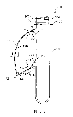
[00025] Figure 2 is a side view of a preferred embodiment of a preform and
integrally
attached handle according to the invention,
[00026] Figure 3 is an end view of the preform and handle of Figure 1,
[00027] Figure 4 is a view from above of the preform and handle of Figures 1
and 2,
[00028] Figures 5A to 5C show cross sections at various locations of the
handle of Figures
2 to 4,
[00029] Figure 6 is a side view of a container which may be stretch blow-
moulded from
the preform shown in Figures 2 to 4,
CA 03019684 2018-10-02
WO 2017/173477 PCT/AU2017/000082
[00030] Figure 7 is a plan view of a possible stretch blow-moulding machine
suitable for
the production of the container of Figure 6 from the preform of Figures 2 and
3,
[00031] Figure 8 is a side view of a preform in transit on a transport
system of the machine
of Figure 7,
[00032] Figure 9 and 9A illustrate a method of feeding and orienting a
preform with
integral handle for use in the machine of Figure 7,
[00033] Figure 10 is a partial cross section view of the integral handle of
a preform nested
in a heat shield,
[00034] Figure 11 is a view of a perform with integral handle entered into
a stretch blow-
moulding die for blowing into a container such as shown in Figures 1 and 6.
DESCRIPTION OF EMBODIMENTS
[00035] In this specification the term "integral connection" or "integrally
connected" means
a connection between the handle and the preform (and subsequently the
corresponding
connection on the container blown from the preform) which is made from the
same material
as the handle and the preform and is formed as an inherent part of an at the
same time as the
preform is formed.
[00036] The preform and integrally attached handle of the present invention is
for the
production of a stretch blow-moulded container of oriented PET material which
includes an
integral handle, as shown in Figure 6. There are basically two types of
processes for stretch-
blow moulding a container from polymer material: 1) a single-stage process in
which
preforms are made and containers blown on the same machine, and 2) a two-stage
process in
which preforms are made on one machine and blown into the container later,
possibly at
another remote location, on another machine.
[00037] Single-stage equipment is capable of processing PVC, PET, and PP. Once
the
preform or parison is formed (either extruded or injection moulded), it passes
through
conditioning stations which bring it to the proper orientation temperature.
The single-stage
system allows the process to proceed from raw material to finished product in
one machine,
but since tooling cannot be easily changed, the process is best suited for
dedicated
applications and low volumes.
6
CA 03019684 2018-10-02
WO 2017/173477 PCT/AU2017/000082
[00038] With the two-stage process, processing parameters for both preform
manufacturing and container blowing can be optimized. A processor does not
have to make
compromises for preform design and weight, production rates, and container
quality as he
does on single-stage equipment. He can either make or buy preforms. And if he
chooses to
make them, he can do so in one or more locations suitable to his market. Both
high-output
machines and low output machines are available. In the two stage process,
preforms will be
introduced into the stretch blow-moulding machine at ambient temperature and
will require
special pre-heating arrangements before preforms enter the blow-moulding die.
[00039] In this specification the term "integral connection" or "integrally
connected"
means a connection between the handle and the preform (and subsequently the
corresponding
connection on the container blown from the preform) which is made from the
same material
as the handle and the body of the preform and is formed as an inherent part of
the injection
moulded preform.
[00040] Figure 1 shows a container according to prior art, stretch blow-
moulded from a
preform (Figure 1A) which includes an integral handle. As can be seen in the
end view of
Figure 1B, the handle forms a constant width profile throughout its length
between the upper
connection region and the lower connection region. Although the "I-beam" form
of the handle
profile provides strength, the relatively narrow area adjacent the upper
connection region
renders this form of handle uncomfortable, even painful to hold for any
extended period,
particularly for containers with large, for example 21itre or greater volumes.
[00041] Turning now to Figure 2, in a preferred form of the present invention,
a preform
100 includes a neck 102, a body portion 103 and a handle 113. The neck 102 has
a threaded
portion 104 and a locating ring 105. The preform is injection moulded from PET
material. It
can be seen in Figure 6, that in the present invention, the handle in its
configuration as
injection moulded in its preform state, remains unaltered by the stretch blow-
moulding
process forming the container of Figure 6.
[00042] In order to produce the container shown in Figure 6, the preform
100 shown in
Figures 2 to 4, according to an embodiment of the invention, is fed into a
blow moulding
machine such for example as the machine 510 shown schematically in Figure 7,
and blow
moulded according to bi-axial orientation blow moulding techniques. During
this process the
neck 102 is held in a mandrel 513, as shown in Figures 8 and 10 of a transport
system of the
machine 510 in such a way as to prevent its expansion in the stretch blow-
moulding die 517.
7
CA 03019684 2018-10-02
WO 2017/173477 PCT/AU2017/000082
[00043] Initially, the expandable portion of the preform below the neck can
be
mechanically stretched downwardly to the bottom of the mould and then the bulk
of the
preform can be blown outwardly by application of compressed air as well known
in the art.
[00044] .. In one preferred form, with reference to Figure 7, a stretch blow
moulding
machine 510 includes a chain drive transport mechanism 516 which has a
plurality of
mandrels 513 mounted thereon at substantially equally spaced intervals, such
that each
mandrel follows a generally oval path through various processing stations on
the machine
510.
[00045] With reference to Figures 7 and 8, a preform 100 mounted on a
mandrel 513, as
shown in Figure 8, proceeds from a loading station 515 of the machine 510 via
a series of
conditioning heaters 521 to a stretch blow moulding station 517 and thence to
unloading
station 518. A separate drive system 522 ensures that the preforms are rotated
as they pass by
the heaters 521 to ensure even heating of the preform body.
[00046] .. As illustrated in Figure 8 each mandrel 513 includes a heat shield
519. Although
this heat shield is for a different configuration of preform handle to that of
the present
invention, the process of mounting in a mandrel provided with a heat shield,
the pre-heating
of the preform and its progress through the stretch blow-moulding stage, are
identical in
principle to the processes applied to the preform and handle of the present
invention.
[00047] The heat shield 519 is adapted to receive within it the integral
handle 113 of
preform 100 for the purpose of shielding handle 113 against heat imparted by
the radiant
heaters 521 as the preform is transported through the heating stage in the
direction indicated
by the arrow in Figure 7.
[00048] It will be understood that the orientation of the handle must be
controlled at the
point where the preform is inserted into a mandrel prior to the entry of the
preform into the
heating stage to enable the heat protective shield 519 to be correctly fitted
over the handle
113.
[00049] Furthermore, it is essential that each preform 100 is presented to
the stretch blow-
moulding tool 517 with the handle and heat shield correctly oriented so that
the handle and
heat shield are correctly enclosed in the halves of the mould when this closes
for the blowing
stage as shown in Figure 11.
8
CA 03019684 2018-10-02
WO 2017/173477 PCT/AU2017/000082
[00050] With reference to Figures 9 and 9A, in one preferred arrangement,
preforms 100
are fed from a suitable supply source, (such as for example a hopper or a
vibratory bowl as
shown in Figure 7) to an infeed rail 724 at a loading station 530. Infeed rail
724 is arranged so
that preforms 100 progress along rail 724, either by gravity, vibration or
other linear
transporting means, supported between parallel rail elements 725 and 726 at
the underside of
locating ring 105, as shown in Figure 9.
[00051] The orientation of the handles 113 of the preforms during transport
along infeed
rail 724, is preferably controlled by a guiding channel (not shown) to loosely
constrain the
handles from assuming an orientation approaching, or at right angles to the
direction of travel.
Preforms 100 are thus constrained to proceed along infeed rail 724 either with
the handle 113
pointing generally forward of the body 103 or trailing it. An escapement (not
shown) at the
end of infeed rail 724 provides for control of sequential discharge of
individual preforms 100
from the end of the rail.
[00052] Preforms thus released from infeed rail 724, are allowed to drop
vertically into an
orienting apparatus 732 shown in Figure 9A fixed directly below the escapement
at the end of
infeed rail 724. In a preferred form, the orienting apparatus 732 shown in
Figure 9A consists
of a truncated cylindrical sleeve 734 which has an internal diameter adapted
to allow free
sliding passage of the cylindrical body 103 of the preform and locating ring
105. The wall of
the sleeve 734 is provided with a slit 736 extending the length of the sleeve
734 from a handle
inlet opening 738 at the upper edge 749 of the sleeve 734, to a handle outlet
opening 740 at
the lower edge 741. The slit is of sufficient width to allow sliding passage
of the handle 113
of a preform 100.
[00053] The upper edges 745 and 743 of sleeve 734 are formed to guide a
handle 113 into
the slit 736. For this purpose the upper edges 745 and 743 are formed to slope
steeply from
respective high points 744 and 744A diametrically opposite the handle inlet,
down to the
handle inlet opening 738 of slit 736. To ensure that the handle does not fall
onto and become
lodged on the highest points on upper edges 743 and 745, the infeed rail 724
is arranged
approximately at right angles to the radial position of slit 736. Thus handles
113 which, as
described above are prevented from assuming this orientation while conducted
along the
infeed rail 724, cannot contact the upper edges 743 and 745 at the highest
points, but will
rather drop onto the orienting device with the handle contacting either
sloping upper edge 743
or 745.
9
CA 03019684 2018-10-02
WO 2017/173477 PCT/AU2017/000082
[00054] Sloping edges 743 and 745 slope down to respective sides of the
slit 736, from the
highest points 744 and 744A, ending in respective smoothly rounded corners 748
and 749 at
the handle inlet opening 738. The slope is sufficient to ensure that the
handle 113 of the
preform 100 slides along the sloping edge sections.
[00055] A preform 100 falling into the apparatus 732 with a handle 113 not
aligned with
slit 736 will, as the handle makes contact with either sloping section 743 or
745, be rotated as
it slides down under its own weight, until handle 113 is aligned with slit 736
and the preform
712 falls cleanly through the apparatus.
[00056] Arranged immediately below apparatus 732 is a rotary indexing table
(not shown)
provided around its periphery with a number of equally spaced nests, so
situated that each
successive nest comes to an aligned position with the axis of apparatus 732 at
each indexing
of the indexing table. Nests are adapted to receive a preform 100 and retain
it in such a way
that the orientation of the handle 113 initially imposed by apparatus 732 is
maintained relative
to each nest for the duration of the preform's retention in the nest.
[00057] When, with the indexing of the table, a preform 100 reaches a
transfer station 515
(see Figure 7), the preform is ejected upwardly out of the nest in which it
was supported, to
engage with one of a series of mandrels 513 of the preform transport system
516, operating
between the loading station 515 and the blow-moulding tool 517. A preferred
mandrel
arrangement with a preform attached is shown in Figure 10.
[00058] When inserted into the mandrel 513, the open neck 102 of the
preform 100 is
pushed over a resilient plug 759 located in a cylindrical socket 761 at the
base of the mandrel.
The plug 759 enters the open neck as an interference fit sufficient for the
weight of the
preform 100 to be supported within the socket 761. The socket also acts to
shield the neck 102
from excessive heat during the heating stage.
[00059] The body portion 103 of preforms 100 must be heated to the required
degree of
plasticity so that the material in the body portion 100 of the preform can be
bi-axially oriented
in the stretch-blow-moulding process. However, neither the neck portion 102
nor the handle
113, should be subjected to hi-axial stretch blow moulding and must be
shielded from
excessive heat during the heating stage to prevent their crystallization with
consequent loss of
strength. Thus for transport through the heating stage, the handle 113 of the
preform 100 is
CA 03019684 2018-10-02
WO 2017/173477 PCT/AU2017/000082
protected by the heat shield 519, and the neck portion 102 by the cylindrical
socket 761 of the
mandrel 513, as shown in Figure 10.
[00060] As the preforms 100 are transported past the heating station 521
they are rotated
on the mandrels 513 by a drive mechanism 522 to provide even heating to the
body portion of
the preform while the heat shield 519 protects the handle from excessive
heating.
[00061] Rotation of the mandrels is arranged so that at the point of entry
into the stretch
blow moulding die, the heat shield and the handle are correctly oriented with
the die cavity as
shown in Figure 11. After the container is blown, the transport system draws
the mandrel and
container from the die and the container is ejected from the mandrel.
[00062] Turning now to the specific characteristics of the handle 113
according to the
present invention, the handle is injection moulded integrally with the body
portion of the
preform, and comprises a loop or orientable material extending between an
upper connection
region 115 and a lower connection region 116 on the body portion 103 of the
preform. It can
be described as consisting of two main sections: a lower straight section 118
angling
downwardly from the lower connection region 116 and an arcuate section 120
extending from
an end 121 of the straight section 118 to the upper connection region 115.
[00063] The loop of orientable material forming the handle 113 has a
generally uniform
cross section from proximate the lower connection region 116 to a gradually
widening cross
section 124 approaching the upper connection region 115 with the cross section
reaching and
maintaining a maximum width proximate the upper connection region 115 as can
be seen in
Figures 3 and 4. Figures 5A to 5C show the cross sections at typical regions
of the handle
113. Figure 5A at the straight section 118, Figure 5B for the greater length
of the arcuate
section 120, and Figure 5C for the wider cross section proximate the upper
connection region
115.
[00064] As can be seen from Figures 5A to 5C, the cross section in each
region of the loop
or orientable material forming the handle 113, extends from opposing outer
edges 130 and
131 towards a central line 132; the cross section increasing in thickness
progressively from
the outer edges 130 and 131 to a maximum thickness at the central line 132.
[00065] With reference again to Figure 2, integrally moulded first, second
and third
strengthening elements 135, 136 and 137 are provided respectively at each of
the upper
11
CA 03019684 2018-10-02
WO 2017/173477 PCT/AU2017/000082
connection region 115, the lower connection region 116 and at the junction
between the
straight section 118 and the arcuate section 120 of the handle 113.
[00066] The first strengthening element 135 at the upper connection region
115 comprises
a curved strengthening clement conforming generally in width and in cross
section to the
width and cross section of the widened portion 124 of the handle proximate the
upper
connection region as shown in Figure 5C. The curved strengthening element
extends from a
first separate connection region 140 on the body portion 103 of the preform
(and on the blown
container) below the upper connection region 115 and merges with the loop of
orientable
material proximate a first end 141 of the maximum width of the handle.
[00067] The second strengthening element 136 at the lower connection region
116 of the
handle, comprises a straight strengthening element conforming generally in
width and cross
section with the width and cross section of the straight section 118. The
straight strengthening
element extends from a second separate connection region 142 above the lower
connection
region 116 of the straight section of the handle, to merge with the straight
section of the
handle proximate the lower connection region.
[00068] The third strengthening element 137 at the junction of the straight
section 118 and
the arcuate section 120 of the handle, comprises a further curved
strengthening element
conforming generally in width and cross section with the width and cross
section of the
handle of both the straight section 118 and the arcuate section 120 adjacent
the junction.
Respective outer ends of this further curved element merge with each of the
straight 118 and
arcuate 120 sections.
[00069] It should be noted that the width of the first strengthening
element 135 is the same
as that of the maximum width of the widened part 124 of the handle proximate
the upper
connection region 115. It is this increased width of the first strengthening
element 135 which
provides for a larger area for distributing the load of a container over the
index finger of a
hand (not shown) lifting the container shown in Figure 6, while the curvature
of the first
strengthening element is selected to fit comfortably on the average index
finger of a human
hand.
[00070] Preferably, though not essentially, each strengthening element 135,
136 and 137
includes a web of orientable material within boundaries formed respectively
between the body
portion 112 of the preform and the first and second strengthening elements 135
and 136, and
between the third strengthening element 137 and the straight and arcuate
sections 118 and
12
CA 03019684 2018-10-02
WO 2017/173477 PCT/AU2017/000082
120. Each web of orientable material is aligned with and extends equally in
both directions
from the central line 132 of handle.
[00071] In an alternative form of production equipment rotatable moulds may
be provided
on a turret arrangement for reception of the preforms preparatory to blowing
within the
moulds.
13