Note: Descriptions are shown in the official language in which they were submitted.
CA 03020366 2018-10-09
Device for pressing out a material from a deformable tube
[0002] The present invention relates to a device for pressing a substance out
of a deformable tube.
The tube can consist of plastics material or metal, for example. The substance
to be pressed out
can be in particular an adhesive.
[0003] Devices of this kind for pressing a substance out of a deformable tube
are intended to
make it easier to handle the tube and to press out and apply the substance to
a surface. In
particular the dosing of the substance is intended to be made easier.
[0004] A device for pressing a substance out of a deformable tube is known
from EP 24 90 956
B1 , which device comprises a housing and a squeezer that can be inserted into
the housing, the
squeezer comprising a support element and two jaws positioned opposite one
another for gripping
and squeezing a substance out of the tube. Lever elements are attached to the
jaws for manual
operation of the squeezer.
[0005] It is an object of the present invention to disclose an improved device
for pressing a
substance out of a deformable tube. In particular, the handling of the device
is to be improved to
the effect that the substance can be precisely dosed and the tube emptied,
even with a relatively
low force exertion.
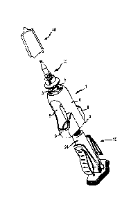
[0006] This object is achieved by the subject matter of the independent claim.
Further
embodiments are the subject matter of the dependent claims.
[0007] According to one embodiment of the invention, a device for pressing a
substance out of a
deformable tube is disclosed, which device comprises a housing having a base
end, an upper
portion opposite the base end and lateral wall portions between the base ends
and the upper
portion. The device further comprises a squeezer that can be inserted into the
housing, the
squeezer comprising a support element and two jaws positioned opposite one
another for gripping
and squeezing a substance out of the tube.
[0008] The housing further comprises an opening in the upper portion, through
which a dispensing
outlet of the tube can be guided, and openings in opposite sides of the
lateral wall portions, by
means of which the jaws can be operated, the jaws being secured at one end to
the support
element and the squeezer furthermore comprising a manual lever element on at
least one jaw.
[0009] The lever element is connected to the jaw in a connection region in an
arrangement in
which pressure applied manually to the lever element produces a force on one
jaw towards the
other jaw. The lever element comprises a body that has reinforcing ribs, the
reinforcing ribs being
1
CA 03020366 2018-10-09
surrounded, at least in part, by a closed outer shell, one region of the outer
shell forming a grip
region.
[0010] According to this embodiment, a device is provided by means of which a
user can squeeze
a substance out of the deformable tube by exerting pressure, in the grip
regions, on the manual
lever elements. This pressure is transferred from the lever element to the
jaws and from the jaws to
the deformable tube.
[0011] The device is advantageous in that the lever element is particularly
suitable for transferring
a relatively low force to the deformable tube in a particularly effective
manner. For this purpose, the
lever element is not completely solid and therefore not completely stiff, but
rather has a degree of
flexibility on account of the reinforcing ribs, without losing load-bearing
capacity. The reinforcing
ribs are in this case not exposed in the grip region but are covered by a
closed outer shell. This
substantially improves the handling of the device, since rib-like structures
exposed in the grip
region can push into the fingers of the user when the device is being handled.
This is at least
uncomfortable but can even be painful, which negatively affects the handling
of the device.
[0012] According to one embodiment of the invention, the lever element has a
concave portion on
the at least one jaw at the same height as the connection region. This has the
object of further
improving the handling of the device. Said portion creates a secure hold for
the fingers of a user
and prevents the fingers from slipping off in the event of pressure being
exerted. Furthermore, the
concave portion visually emphasises the grip region.
[0013] Moreover, the lever element can be convex, for example.
[0014] According to one embodiment of the invention, the radius of curvature r
of the outer shell of
the lever element in the concave portion is 5 mm 5 r 5 50 mm, in particular 16
mm r 5 35 mm. It
has been demonstrated that a portion curved in such a way offers a
particularly secure hold in the
grip region.
[0015] According to one embodiment of the invention, grip ribs are arranged in
the grip region on
the outer shell of the lever element. The grip ribs can be formed for example
as relatively small
elevations of at most 1 mm on the outer shell and can be arranged in
particular so as to be
transverse to the longitudinal direction of the lever element. The object of
the grip ribs is to prevent
the fingers of a user from slipping off and thereby further improve the
handling.
[0016] The grip ribs can be formed for example from the material of the outer
shell and be integral
therewith.
2
CA 03020366 2018-10-09
[0017] According to one embodiment of the invention, the connection region
between the lever
element and the jaw has a length L, L being less than 25% of the length of the
jaw. Length
measurement in this case is assumed to be in the longitudinal direction of the
lever element or the
jaw.
[0018] For example, L is 2 mm L 5 20 mm, in particular 3 mm 5 L 5 12 mm.
[0019] It has been demonstrated that the connection between the lever element
and the jaw, in
the case of said dimensions, is robust and stable enough to reliably transfer
a force exerted by the
user on the lever element to the jaws. However, the connection is relatively
flexible and therefore
makes it easier to handle the device.
[0020] It is furthermore advantageous for the connection region between the
lever element and
the jaw to have a maximum width v, which is at most half of the width b of the
jaw in said region.
For example, v can be at most 7 mm.
[0021] Furthermore, it is additionally advantageous for the connection region
between the lever
element and the jaw to be arranged substantially in the third quarter of the
jaw as seen from the
support element. Therefore, in one embodiment of the device, the connection
region is arranged in
an upper half of the jaw, remote from the support element, but not in the
region of the uppermost
20% of the jaw.
[0022] This arrangement allows an optimal lever action to be achieved. The
connection region
channels the force exerted by a user and distributes it over the entire length
of the jaw. If the
connection region is arranged too close to the opening in the housing and
therefore too close to an
outlet of the tube, problems can arise with respect to handling because the
tube is not sufficiently
flexible in the immediate vicinity of its outlet. Complete emptying of the
tube can also be
problematic.
[0023] If in turn the connection region is arranged so as to be too far
removed from the opening in
the housing and therefore from the outlet of the tube, the leverage exerted on
the jaw is
significantly lower and it is no longer possible to handle the device with low
forces.
[0024] According to one embodiment, the body of the lever element is integral
with the jaws. This
is advantageous in that the lever element and the jaws can be particularly
flexible and
simultaneously stable.
3
CA 03020366 2018-10-09
[0025] According to one embodiment, the housing is open at the base end
thereof and the
squeezer can be inserted into the housing through the open end thereof and
fixed therein. A secure
connection between the housing and the squeezer can be achieved in this way.
[0026] Embodiments of the invention are described in more detail below with
reference to the
drawings, in which:
Fig. 1 is a schematic perspective view of a housing of a device
according to one
embodiment of the invention;
Fig. 2 is a schematic exploded view of a device for pressing a
substance out of
a deformable tube according to one embodiment of the invention;
Fig. 3 are schematic cross-sectional views of a squeezer according to
one
embodiment of the invention;
Fig. 4 is a schematic partially cross-sectional view of a connection
region of the
squeezer according to Fig. 3 and
Fig. 5 is a schematic side view of a squeezer according to one
embodiment of
the invention that can be inserted into the housing according to Fig. 1.
[0027] Fig. 1 shows an empty housing 1 of a device for pressing a substance
out of a deformable
tube according to one embodiment of the invention. The housing 1 comprises an
open base end 2
and an upper portion 3 opposite the base end 2, and lateral wall portions 4
that form the housing 1
between the base end 2 and the upper portion 3. A squeezer (not shown in Fig.
1) having a tube
can be inserted through the open base end 2. A dispensing outlet of the tube
can be guided
through an opening 5 in the upper portion 3.
[0028] The housing 1 further comprises one opening 8 in each of the two
opposite sides, in the
lateral wall portions 4 of said housing. Below the openings 8, the lateral
wall portions 4 project
outwardly and form shoulders 9, such that the open base end does not have a
round cross section
but rather likewise comprises projections.
[0029] Fig. 2 shows the entire device for pressing a substance out of a
deformable tube, having
the housing 1 according to Fig. 1, a squeezer 10 that can be inserted into the
housing 1 and has a
tube 24, an application nozzle 30 that can be placed on the housing 1 and a
closure cap 40 that
can be placed on the application nozzle 30.
[0030] The squeezer 10, which is shown in detail in Fig. 3 to 5, is guided,
together with the tube
24 inserted therein, through the open base end 2 of the housing 1, such that a
dispensing outlet of
the tube 24 is guided through the opening 5 and lever elements (shown in more
detail in Fig. 3 to 5)
of the squeezer 10 are exposed in the openings 8, or protrude outwardly
through the openings 8.
4
CA 03020366 2018-10-09
[0031] Fig. 3 to 5 show a cross section, or side view, of the squeezer 10. The
squeezer 10
comprises two jaws 12, positioned opposite one another, that interact in the
manner of pliers and
are connected at the lower end 13 thereof to a support element 11. When the
squeezer 10 is
inserted into the housing 1, the support element 11 forms a bottom of the
housing 1.
[0032] In a resting state, the jaws 12 diverge from one another at the upper
end 14 thereof. This is
shown in Fig. 3a. A tube, for example an adhesive tube, can be arranged
between the jaws 12,
such that the jaws 12 abut the outer tube wall.
[0033] Each jaw 12 comprises a lever element 15 that can be manually operated,
i.e. by a user
and by hand. Each lever element 15 is connected to the jaw 12 in a connection
region 20. Said
element can be produced for example as an injection-molded part so as to be
integral with the jaw
12. The connection region 20 extends in the longitudinal direction of the jaw
12, or of the lever
element 15, and, in the embodiment shown, is arranged substantially in the
third quarter of the jaw
12 as seen from the support element 11, that is to say, in the upper half of
the jaw 12, remote from
the support element 11, but not in the region of the uppermost 20% of the jaw
12. A very effective
lever action is achieved as a result, which allows the tube to be squeezed
very precisely and with
relatively low force exertion, simultaneously allowing residue to be emptied
effectively from the tube.
The force required to squeeze the tube is typically in the range between 18
and 28 N, in particular
between 20 and 25 N.
[0034] Furthermore, the connection region 20 merely extends at most over a
quarter of the length
of the jaws 12, such that the jaws 12 remain flexible. High flexibility of the
jaws 12 is also achieved
by the connection region 20 having a maximum extent in the transverse
direction of half the width
of the jaws 12. In the embodiment shown, the connection region 20 is 6.8 mm
wide at the widest
point thereof.
[0035] The lever element 15 comprises a body 16 having reinforcing ribs 17.
Said ribs cause the
lever element 15 to be sufficiently stable despite its non-solid formation.
Solid formation of the lever
element 15 would lead to a lack of flexibility and thus to more difficult
handling of the device. The
reinforcing ribs 17 can be formed transversely to the longitudinal direction
of the lever element 15,
as shown in Fig. 3a to 3c. However, they can also extend in a different
direction and/or reinforcing
ribs 17 that extend in a plurality of directions or curved reinforcing ribs 17
can be provided.
[0036] The reinforcing ribs 17 are not exposed at the surface of the lever
element 15 at least in a
grip region 19 of the lever element 15, but instead are surrounded, or
covered, by an outer shell 18.
A user of the device therefore does not come into contact with exposed
reinforcing ribs 17 when
using the device in the intended way. The outer shell 18 can surround the
lever element 15
completely or only in specific regions. In the embodiment shown, the
reinforcing ribs 17 (as can be
CA 03020366 2018-10-09
seen in Fig. 4) are laterally exposed by the grip region 19 and not encased in
said region by the
outer shell 18.
[0037] The lever element 15 has a concave portion 21 at the same height as the
connection
region 20, in which portion the grip region 19 is formed concavely in order to
offer a better
fingerhold.
[0038] The functioning of the squeezer when a tube (not shown in the drawings
for sake of clarity)
is squeezed is explained with reference to Fig. 3a to 3c.
[0039] Fig. 3a shows the squeezer 10 in a first position, also referred to as
a resting position, in
which no force is exerted on the lever elements 15. The jaws 12 are opened
wide.
[0040] Fig. 3b shows the squeezer 10 in a second position, which represents an
intermediate
position and which is assumed when a degree of force is exerted on the lever
elements 15 and
thus on the jaws 12 by a user pushing together the lever elements 15 using
their fingers. In said
intermediate position, the jaws 12 still significantly diverge from one
another at the upper end 14
thereof, yet are already in contact with one another in the lower third. It
can be seen here that the
jaws 12 are not simply pushed together by the exertion of force on the lever
elements 15, but rather
in each case are bent in on themselves. In particular, the arrangement and
design of the
connection region 20 allows the jaws 12 to bend and as a result allows
particularly effective
emptying of the tube from below.
[0041] Fig. 3c shows the squeezer 10 in a third position, in which the jaws 12
are fully in contact
with one another and which is assumed when, proceeding from Fig. 3b, force is
further exerted on
the lever elements 15.
[0042] Fig. 3a to 3c show the squeezer 10 without a tube inserted therein.
When a tube is
arranged between the jaws 12, the jaws 12 can no longer contact one another.
Instead of contact,
close convergence then occurs with a firmly squeezed tube arranged
therebetween.
[0043] Fig. 4 shows the connection region 20 between the jaw 12 and the lever
element 15 (not
shown in this view). It can be seen here that the connection region 20 has a
maximum width v in
the region of the upper end thereof. In this case, v is at most half of the
width b of the jaw 12 in said
region.
[0044] Fig. 5 is a side view of the squeezer 10. Grip ribs 22 can be seen
therein, which are
arranged in the grip region 19 on the outer shell 18 and which are intended to
prevent the fingers of
6
CA 03020366 2018-10-09
the user from slipping off. The grip ribs 22 can for example be designed as
moldings on the outer
shell 18 itself.
7
CA 03020366 2018-10-09
List of reference signs
1 housing
2 base end
3 upper portion
4 lateral wall portion
opening
8 opening
9 shoulders
squeezer
11 support element
12 jaw
13 first end
14 second end
lever element
16 body
17 reinforcing ribs
18 outer shell
19 grip region
connection region
21 concave portion
22 grip ribs
24 tube
application nozzle
closure cap
8