Note: Descriptions are shown in the official language in which they were submitted.
FRAME POSITIONING DEVICE FOR POSITIONING A FRAME
OVER AN INLET OF A CATCH BASIN OR MANHOLE AND
METHOD FOR POSITIONING THE SAME
TECHNICAL FIELD
The invention relates to a positioning device and more particularly to a
positioning device for
installing a frame over an inlet of a catch basin or a manhole.
BACKGROUND
During road construction, catch basins and sewer inlets are disposed at
various locations on
concrete or paved roads to evacuate excess rain water and ground water or
small debris, and to
give access to the drainage system below.
There are two main types of water drainage systems: side inlets and covered
inlets. Side inlets
are usually located at the curb of a street or under the sidewalk, and the
pavement of the street
is often angled towards the curb to direct the flow of water and small debris
by gravity
towards the curb. Covered inlets are typically installed in a concrete or
paved street or road
and comprise a grate or cover which prevents large debris from accessing the
inlet. Covered
inlets are usually mounted onto a frame for covering an inlet of a manhole or
catch basin. The
manhole or catch basin often connects to a sewage system having a plurality of
interconnected
pipes.
Installing a frame and a covered inlet onto an inlet of a catch basin or
manhole can be
challenging and requires industrial equipment adapted to lift heavy loads.
Furthermore,
covered inlets may sometimes not be properly leveled with the concrete or
paved road which
can create problems for vehicles. For example, in cold countries where
temperature can reach
below freezing, snow removal vehicles are needed to remove snow and/or ice
from the streets.
During the removal of snow, a mechanical shovel is usually mounted in front of
the snow
removing vehicle and scrapes the snow and/or ice laterally to the side of the
street. If the
covered inlets are not well leveled with the concrete or paved road, the
covered inlets may
inadvertently be removed during a snow removal process. This situation may
create
¨ 1 -
CA 3020452 2018-10-10
significant circulation problems or could even create a danger for pedestrians
or even vehicles
circulating on the street.
In other situations, such as on busy traffic arteries of big cities or even on
highways, vehicles
such as long haul trucks and cars may repetitively travel on covered inlets.
The repetitive
pressure of vehicles on covered inlets may in certain situations lift the
covered inlets from the
frame, which may create significant traffic problems and may also endanger
pedestrians.
Given the above drawbacks, there is therefore a need for a positioning device
adapted to
position a frame over an inlet of a catch or a manhole and/or a grate locking
system which
overcomes at least one of the previously identified drawbacks.
SUMMARY
According to a first broad aspect, there is provided a device for positioning
a frame over a
head of one of a catch basin and a manhole, the device comprising:
an elongated body
extending between a first end and a second end, the elongated body having an
adjustable
length, the first end second ends of the elongated body being adapted to abut
opposite sections
of a top face of the head; and a first leveling member and a second leveling
member each
secured to the elongated member such that a distance between the first and
second leveling
members varies when the length of the elongated body varies, the first and
second leveling
members each comprising: a guide member extending from the elongated member;
and a
frame receiving member slidably and rotatably secured to the elongated member,
the frame
receiving member being configured for receiving and supporting a lower end of
the frame in
order to position and orient the frame relative to the head.
In one embodiment, the elongated body comprises a tubular section and a male
section
slidably inserted into the tubular section, the first leveling member being
secured to the
tubular section and the second leveling member being secured to the male
section.
In one embodiment, the device further comprises a securing mechanism for
securing the
tubular section and the male section together.
¨ 2 -
CA 3020452 2018-10-10
In one embodiment, the guide member of the first and second leveling members
is removably
secured to the elongated body.
In one embodiment, the frame receiving member comprises a first plate provided
with an
aperture for receiving the guide member therein, and a second plate and a
third plate each
extending form the first plate to form a U-shaped space for receiving the
lower end of the
frame therein.
In one embodiment, the first leveling member and the second leveling member
each further
comprise a locking mechanism for securing the frame receiving member to the
guide member.
In one embodiment, the first end and the second end of the elongated body each
comprise a
cantilevered section for abutting the opposite sections of the top face of the
head.
According to another broad aspect, there is provided a frame positioning
device for
positioning a frame in a desired position over an inlet of one of a catch
basin and a manhole,
the inlet including an opening and a rim surrounding the opening, the
positioning device
comprising: an elongated body having a first end portion adapted to be
supported on the rim
and a second end portion adapted to be supported on the rim opposite the first
portion such
that the body extends across the opening; first and second leveling members
extending
upwardly from the body, the first leveling assembly being located towards the
first end portion
and the second leveling assembly being located towards the second end portion,
each leveling
assembly including a guide member attached to the body and a receiving member
movably
connected to the guide member for receiving a lower end portion of the frame,
the receiving
member being movable generally vertically towards and away from the body to
allow the
frame to be positioned and angled in a desired position relative to the inlet.
In one embodiment, each one of the first and second abutment portions includes
a cantilevered
section which extends away from the other one of the first and second abutment
portions.
In one embodiment, each receiving member includes a pair of vertical walls for
receiving the
lower edge of the frame therebetween.
¨ 3 -
CA 3020452 2018-10-10
In one embodiment, the body includes a first tube and a second tube
telescopically mounted
within the first tube, the first end portion being defined on the first tube
and the second end
portion being defined on the second tube, the first and second tube being
movable relative to
each other between a closed position in which the first end portion and the
second end portion
are spaced by a first distance and a deployed position in which the first end
portion and the
second end portion are spaced by a second distance greater than the first
distance.
In one embodiment, the device further comprises a locking handle for locking
the first and
second tubes together in the deployed position.
According to a further broad aspect, there is also provided a method for
positioning a frame
over an inlet of a catch basin or manhole, the method comprising: providing at
least one frame
positioning device as described above; positioning the first end portion of
the at least one
frame positioning device on a rim of a concrete head and the second end
portion of the at least
one frame positioning device on the rim opposite the first end portion such
that the body
extends across the opening; moving a lower edge of the frame and a
corresponding receiving
member towards each other until the lower edge is received in the receiving
member;
vertically moving the at least one supporting member along a displacement
member to a
desired vertical location.
In one embodiment, positioning the lower edge of the frame onto the supporting
members
comprises aligning each recess of the lower edge of the frame with each
supporting members.
In one embodiment, the method further comprises positioning a covering layer
around the
frame and a guide.
In one embodiment, the covering layer is a geotextile membrane.
In one embodiment, the method further comprises installing a cover or grate on
the frame.
In one embodiment, installing a cover or grate on the frame comprises
deforming the cover or
grate by elastic deformation to fit the cover or grate on a cover receiving
shoulder of the
frame.
In one embodiment, the method further comprises locking the cover or grate on
the frame.
¨ 4 -
CA 3020452 2018-10-10
In one embodiment, locking the cover or grate on the frame comprises inserting
a locking
member in an opening for pressure fitting the cover or grate against the cover
receiving
contour of the frame.
BRIEF DESCRIPTION OF THE DRAWINGS
Figure 1 is an exploded perspective view of a cover or grate assembly disposed
over a
concrete head of a catch basin or a manhole and maintained in a desired
position and
orientation using a pair of positioning devices, in accordance with one
embodiment;
Figure 2 is a top front perspective view of a guide of the grate assembly
illustrated in Figure 1;
Figure 3 is a bottom front perspective view of the guide illustrated in Figure
2;
Figure 4 is a perspective view of one of the positioning devices illustrated
in Figure 1;
Figure 5 is an enlarged perspective view of area A of Figure 4;
Figure 6 is a side elevation view of the positioning device illustrated in
Figure 4;
Figure 7 is a top perspective view of a frame of the grate assembly
illustrated in Figure I;
Figure 8 is a perspective view of a grate of the grate assembly illustrated in
Figure 1;
Figure 9 is a cross-section view taken along cross-section line D of the grate
of Figure 8;
Figure 10 is a perspective view illustrating the positioning of the guide
illustrated Figure 2
onto a concrete head;
Figure 11 is a top view illustrating the positioning devices illustrated in
Figure 1 in their
deployed position in the corresponding recesses of the guide and on the
concrete head;
Figure 12 is a cross-section view illustrating the positioning of the leveling
assemblies onto
one of the positioning devices illustrated in Figure 1, during the
installation of the frame;
Figure 13 is a cross-section view illustrating the positioning of the frame of
Figure 7 onto the
positioning device of Figure 4;
¨ 5 -
CA 3020452 2018-10-10
= ,
Figure 14 is an enlarged view of the positioning of the frame of Figure 7 onto
the positioning
device of Figure 4;
Figure 15 is a schematic side view showing the grate assembly of Figure 1
installed over the
catch basin or manhole;
Figure 16 is a top perspective view of the grate assembly of Figure 1, showing
the grate being
compressed and installed in the frame; and
Figure 17 is a perspective view of a further positioning device, in accordance
with another
embodiment.
It will be noted that throughout the appended drawings, like features are
identified by like
reference numerals.
DETAILED DESCRIPTION
Figure 1 shows a cover or grate assembly 100 disposed over a concrete head
104, such as a
concrete head for a catch basin or a manhole, and maintained in a desired
position and
orientation using a pair of positioning devices 300a and 300b, in accordance
with one
embodiment. As known in the art, a head such as the head 104 is to be
installed and secured
within a hole such as a catch basin or a manhole. The concrete head 104
includes an opening
or inlet 102 and a rim or upper edge surrounding the inlet 102 on its upper
face, i.e. on the
face of the head 104 to face the grate or cover.
The grate assembly 100 includes a frame 400 to be disposed above the concrete
head 104. In
one embodiment, the grate assembly 100 further comprises a guide 200 to be
positioned on
top of the head 104 for guiding the frame 400 with respect to the head 104 as
illustrated in
Figure 1 and further described below.
A grate 500 is further to be positioned onto the frame 400 for allowing
passage of excess
water and small debris which can be found in streets into the catch basin or
manhole while
preventing the passage of larger debris. Alternatively, instead of a grate
500, the cover or grate
assembly 100 could comprise a cover.
¨ 6 -
CA 3020452 2018-10-10
When the grate assembly 100 is properly installed, the frame 400 is positioned
and angled in a
desired position and angle such that a top surface of the frame 400 generally
lies in a plane
corresponding to the current or desired top surface of the road above the
concrete head 104.
For example, once installed, the top surface of the grate or cover may be
substantially
coplanar with the top surface of the road. In the illustrated embodiment, a
concrete road layer,
best shown in Figure 15, is further poured around the frame 400 to define the
road surface
above the concrete head 104, as well as to maintain the frame 400 in its
desired position and
angle.
The cover or grate assembly 100 further comprises a positioning system or
apparatus to be
positioned on top of the head 104 and configured for supporting the frame 400.
The
positioning system is configured for adjusting an orientation of the frame 400
relative to the
head 104 and a distance between the frame 400 and the head 104.
In the illustrated embodiment, the positioning system comprises two
positioning devices 300a
and 300b which are generally elongated and are received on top of the rim or
upper edge of
the head 104. The positioning devices 300a and 300b are used to help position
the frame to its
desired position and/or angle relative to the head 104 during the creation of
the road surface
around the frame 400, and can be removed once the road surface is set and the
frame 400 is
held into position.
Figures 2 and 3 illustrate one embodiment of the guide 200 which is designed
and shaped to
be positioned on the upper edge of head 104 and help to secure the frame 400
over the head
104.
In the illustrated embodiment, the guide 200 has an asymmetrical truncated
circular shape and
comprises a bottom mounting end 210 for mounting to the head 104 and a top
receiving end
218 adapted to receive the frame 400. The bottom mounting end 210 includes a
base 202
which has an outer edge 206, an inner edge 208 and a bottom mounting surface
204 defined
between the outer and inner edges 206, 208 and adapted to be placed against
the head 104.
The guide 200 further comprises a first straight wall portion 212, a second
straight wall
portion 214 opposed to the first wall portion 212, and a pair of outwardly
convex walls 216a
¨ 7 -
CA 3020452 2018-10-10
and 216b extending between the first wall portion 212 and the second wall
portion 214. The
first wall portion 212, the second wall portion 214, and the pair of outwardly
convex walls
216a and 216b extend upwardly from the inner edge 208 of the base 202 to the
top receiving
end 218 of the guide 200. In the illustrated embodiment, the first wall
portion 212 and the
second wall portion 214 are parallel to each other and the first wall portion
212 is shorter than
the second wall portion 214. Still in the illustrated embodiment, the first
wall portion 212, the
second wall portion 214 and the pair of outwardly convex walls 216a and 216b
thereby define
an opening 220 which may be sized and shaped generally similarly to the inlet
102 such that
when the guide 200 is mounted on the catch basin or manhole 100, the opening
220 is in
vertical alignment with the inlet 102. Alternatively, the wall portions could
be configured
differently.
In the illustrated embodiment, the first wall portion 212, the second wall
portion 214 and the
pair of outwardly convex walls 216a and 216b are slightly angled inwardly so
as to center the
frame 400 once received in the top receiving end 218 of the guide relative to
the inlet 102.
Alternatively, the wall portions could instead be vertical instead of being
angled.
Still in the illustrated embodiment, the base 202 further comprises a
plurality of recesses 222a,
222b, 222c and 222d defined in the bottom mounting surface 204 of the base
202. As best
shown in Figure 1, when the guide 200 is placed on the head 104, pockets or
chambers are
defined between the recesses 222a, 222b, 222c and 222d and the top face of the
head 104. The
chambers are sized and shaped so as to each receive a respective end of the
one of the
positioning devices 300a and 300b, which are supported by the concrete head
104.
Specifically, recesses 222a and 222d are located on opposite sides of the
opening 220 and are
adapted to receive the first positioning device 300a, as will be further
explained below.
Similarly, recesses 222b and 222c are also located on opposite sides of the
opening 220 and
are adapted to receive the second positioning device 300b, as will also be
explained further
below.
In one embodiment, each outwardly convex wall 216a and 216b comprises opposed
ribs 224
and 226 which extend away from the convex wall 216a and 216b towards the outer
edge 206
of the base 202, and are secured to the base 202. The first wall portion 212
also comprises a
¨ 8 -
CA 3020452 2018-10-10
central rib 228 which extends away from the first wall portion 212 towards the
outer edge 206
of the base 202, and is secured to the base 202. It will be appreciated that
the ribs 224, 226 and
228 may provide structural reinforcement to the guide 200, as well as provide
stability when
multiple guides are stacked on top of each other and further facilitate the
packaging of
multiple guides together.
In one embodiment and as illustrated in Figures 2 and 3, the guide 200 also
includes a circular
hole 230 defined in the base 202, generally between the central rib 228 and
the recess 222c.
Alternatively, the guide 200 may not include the hole 230.
In one embodiment, the guide 200 is made of cast iron. Alternately, the guide
200 may be
made of another robust material such as reinforced polymer or another metal.
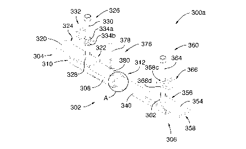
Figures 4 to 6 illustrate one embodiment of the positioning device 300a
adapted for the
installation of the frame 400 within the guide 200 over the inlet 102. The
positioning devices
300a and 300b being generally identically construed, only positioning device
300a will be
described. The person skilled in the art will appreciate that a similar
description also applies to
positioning device 300b.
In one embodiment, the positioning device 300a comprises an elongated body 302
which
extends between a first end portion 304 and an opposed second end portion 306.
As described
below, the elongated body 302 is provided with an adjustable length.
In the illustrated embodiment, the first end portion 304 and the second end
portion 306 are
adapted to abut the upper edge of the head 104 so as to engage the head 104.
Furthermore, the
first end portion 304 and the second end portion 306 are sized and shaped to
be received in the
recesses 222a and 222d of the guide 200, respectively. Alternatively, the
first end portion 304
and the second end portion 306 could be received in the recesses 222c and 222d
of the guide
200.
Still in the illustrated embodiment, the body 302 comprises a first elongated
tube 308 having a
generally rectangular section. The first tube 308 extends between a first end
310 and a second
end 312 located opposite to the first end 310. The first elongated tube 308
comprises a top
wall 314, a bottom wall 316 and a pair of lateral walls 318a and 318b.
¨ 9 -
CA 3020452 2018-10-10
In one embodiment, the first end portion 304 of the elongated member 302
comprises a first
abutment member 320 having a generally rectangular shape. The first abutment
member 320
comprises a securing section 322 secured to the top wall 314 of the first
elongated tube 308
and a cantilevered section 324 extending longitudinally away from the securing
section 322.
The cantilevered section 324 is sized and shaped so as to be received by in
one of the
chambers defined by one of the recesses 222a, 222b, 222c and 222d and the top
surface of the
head 104.
The securing section 322 may be secured to the top wall 314 of the first
elongated tube 308 by
welding, by using fasteners or by any other appropriate fastening technique.
In one
embodiment, the first abutment member 320 could even be integrally formed
within the first
elongated tube 308.
In one embodiment, the cantilevered section 324 of the first abutment member
320 is adapted
to be received in recess 222a of the guide 200 and to be supported by the
upper edge of the
head 104. It should be understood that the cantilevered section 324 may also
be sized and
shaped so as to be received by in one of the chambers defined by one of the
recesses 222b,
222c and 222d and the top surface of the head 104.
In one embodiment, the cantilevered section 324 extends two inches away from
the first end
310 of the first elongate tube 308. Alternatively, the cantilevered section
324 could have a
different size and/or configuration.
In the illustrated embodiment, the first elongated tube 308 further comprises
a first leveling
assembly 326 adapted to receive a lower end of the frame 400. In the
illustrated embodiment,
the first leveling assembly 326 is secured to the securing section 322 of the
first abutment
member 320. In one embodiment, the first leveling assembly 326 may be
removably secured
to the securing section 322 by a bushing 328.
In one embodiment, the first leveling assembly 326 comprises a first guide or
displacement
member 330, extending vertically from the first abutment member 320. The first
leveling
assembly 326 further comprises a first receiving or supporting member 332
adapted to receive
the lower end of the frame 400. The first supporting member 332 is movably
connected to the
¨ 10 -
CA 3020452 2018-10-10
=
displacement member 330 and is adapted to selectively move vertically along
the
displacement member 330. The first supporting member 332 may also be rotatably
connected
to the displacement member 330 so that the first supporting member 322 may
rotate about the
displacement member 330.
In one embodiment, the first supporting member 332 is sandwiched between an
upper locking
member 334a and a lower locking member 334b to maintain the first supporting
member 332
at a desired vertical location along the first displacement member 330.
In one embodiment, the first displacement member 330 is an elongated bolt
removably
secured to the bushing 328. Alternatively, the first displacement member 330
could include
another type of threaded rod.
In yet another embodiment, the first displacement member 330 could instead
include a ball
stud bolt comprising an 0-ring (not shown) removably secured to the securing
section 322 of
the first abutment member 320.
In one embodiment, each locking member 334a and 334b includes a nut adapted to
be
screwed on the first displacement member 330. In use, the locking members 334a
and 334b
are configured for vertically positioning and locking the first supporting
member 332 at a
desired vertical height for receiving the lower end of the frame 400.
The first supporting member 332 comprises a mounting section 336 adapted to be
positioned
on the first displacement member 330 and a receiving section 338 adapted to
receive the lower
end of the frame 400.
In the illustrated embodiment, the receiving section 338 has a generally U-
shaped cross-
section and includes a pair of generally parallel vertical walls 340a and 340b
which each
extend from the mounting section 336 and are spaced apart by a distance
adequate for
receiving the lower end of the frame 400 between the walls 340a and 340b. It
will therefore be
understood that the distance between the walls 340a and 340b is substantially
equal to or
greater than the thickness of the lower end of the frame 400.
¨ 11 -
CA 3020452 2018-10-10
In one embodiment, the mounting section 336 has a generally rectangular shape
and
comprises a plate provided with an aperture therethrough sized and shaped so
as to receive the
first displacement member 330 therein. In one embodiment, the aperture may be
threaded. As
a result, the mounting section 336 is rotatable about the first displacement
member 330 to
position the vertical walls 340a and 340b of the receiving section 338
generally parallel with
the sidewall of the frame 400, such that the lower end of the frame 400 may be
received
between the vertical walls 340a and 340b.
In the illustrated embodiment, the elongated body 302 of the positioning
device 300a further
comprises a second elongated member 340 which may be a tube. Similarly to the
first
elongated tube 308, the second elongated tube 340 has a generally rectangular
section and has
a first end 342 and a second end 344 located opposite the first end 342. The
second elongated
tube 340 comprises a top wall 346, a bottom wall 348 and a pair of lateral
walls 350a and
350b.
In one embodiment, the second elongated tube 340 has a smaller cross-section
than that of the
first elongated tube 308 and is adapted to be slidably received within the
first elongated tube
308. The first and second elongated tubes 308, 340 are adapted to slide
relative to each other
to thereby increase or reduce the length of the body 302. Specifically, the
first and second
elongated tubes 308, 340 are adapted to slide relative to each other between a
closed position
in which the first end portion 304 and the second end portion 306 are spaced
by a first
distance and a deployed position in which the first end portion 304 and the
second end portion
306 are spaced by a second distance greater than the first distance.
As illustrated in Figure 5, the positioning device 300a may comprise a pair of
flat bars 352a
and 352b which are positioned within the aperture defined by the first
elongated tube 308
between the first and second elongated tubes 308 and 340 for providing a flush
fit between the
first and second elongated tubes 308 and 340. This configuration allows
standard-sized tubes
to be used. Alternatively, the second elongated tube 340 could be sized and
shaped to form a
flush fit with the first elongated tube 308 without requiring flat bars.
In one embodiment, the second end portion 306 of the elongated body 302
comprises a second
abutment member 354 which is generally similar to the first abutment member
320. The
¨ 12 -
CA 3020452 2018-10-10
second abutment member 354 comprises a securing section 356 secured to the top
wall 346 of
the second elongate tube 340. The second abutment member 354 further comprises
a
cantilevered section 358 extending longitudinally away from the securing
section 356. The
cantilevered section 356 of the second abutment member 354 is adapted to be
received on the
upper edge of the sleeve 104, within the recess the 222b of the guide 200 for
example.
The second elongated tube 340 further comprises a second leveling assembly 360
adapted to
receive a lower end of the frame 400 for leveling it relative a concrete or
paved road. In this
configuration, the second leveling assembly 360 is secured to the securing
section 356 of the
second abutment member 354. In one embodiment, the second leveling assembly
360 is
removably secured to the securing section 356 by a bushing 362.
In one embodiment, the second leveling assembly 360 comprises a second guide
or
displacement member 364, extending vertically from the second abutment member
354. The
second leveling assembly 360 further comprises a second receiving or
supporting member 366
adapted to receive the lower end of the frame 400. The supporting member 366
is slidably and
rotatably connected to the displacement member 364 and is adapted to
selectively move
vertically along the displacement member 364 and rotate about the displacement
member 364.
In one embodiment, the second supporting member 366 is sandwiched between an
upper
locking member 368c and a lower locking member 368d to vertically maintain the
second
supporting member 366 at a desired vertical location on the second
displacement member 364.
In one embodiment, the second displacement member 364 is an elongated bolt
removably
secured to the bushing 362.
Alternatively, the second displacement member 364 could instead include a ball
stud bolt
comprising an 0-ring (not shown) removably secured to the securing section 356
of the
second abutment member 354.
In one embodiment, each locking member 368c and 368d includes a pair of nuts
adapted to be
screwed on the second displacement member 364. In use, the locking members
368c and 368d
are configured for vertically positioning and locking the second supporting
member 366 at a
desired vertical height for receiving the lower end of the frame 400.
¨ 13 -
CA 3020452 2018-10-10
The second supporting member 366 comprises a mounting section 370 adapted to
be
positioned on the second displacement member 364 and a receiving section 372
adapted to
receive the lower end of the frame 400.
In the illustrated embodiment, the receiving section 372 has a generally U-
shaped cross-
section and includes a pair of spaced apart vertical walls 374c and 374d which
are spaced
apart to receive the lower end of the frame 400.
In one embodiment, the mounting section 370 has a generally rectangular shape
and
comprises a plate provided with an aperture therethrough sized and shaped so
as to receive the
second displacement member 364 therein. In one embodiment, the aperture may be
threaded.
As a result, the mounting section 370 is adapted to rotate around the second
displacement
member 364 to position the vertical walls 374c and 374d of the receiving
section 372
generally parallel with the sidewall of the frame 400, such that the lower end
of the frame 400
may be received between the vertical walls 374c and 374d.
In one embodiment, the positioning device 300a further includes a locking
mechanism 376 for
locking the first and second tubes 308, 340 relative to each other in the
deployed position.
Specifically, the locking mechanism 376 prevents the first and second tubes
308, 340 from
longitudinally moving relative to each other.
In one embodiment, the locking mechanism 376 comprises a locking handle 378
including a
rod extending through a bushing 380 secured to the top wall 314 of the first
elongated tube
308 and through the top wall 314. The rod of the locking handle 378 is further
adapted to
extend through a corresponding hole defined in the second tube 340 near its
first end 342. In
this embodiment, when the positioning device 300a is in the deployed position,
the rod of the
handle 378 is aligned with the hole defined in the second tube 340.
In one embodiment, the positioning device 300a is made of steel.
Alternatively, positioning
device 300a could be made of another rigid material such as another metal or
reinforced
polymers.
¨ 14 -
CA 3020452 2018-10-10
Turning now to Figure 7, the frame 400 comprises a hollow body 402 including a
closed
sidewall 410 defining a passageway 406 and a flange 428 extending generally
perpendicularly
to the sidewall 410.
In the illustrated embodiment, the sidewall 410 has a generally asymmetrical
truncated
circular shape, similar to the general shape of the opening 220 of the guide
200. The hollow
body 402 is adapted to be received in the opening 220 of the guide 200 through
the top
receiving end 218 of the guide 200. The hollow body 402 is positioned onto the
supporting
members of the pair of positioning devices 300a and 300b.
In one embodiment, the hollow body 402 has a smaller section than the opening
220 of the
guide 200 for enabling a tilt of the frame 400 relative the guide 200 during
leveling with a
concrete or paved road.
The hollow body 402 has an upper end 404 which defines an inlet of the
passageway 406, and
a lower end 408 which defines an outlet of the passageway 406. The sidewall
410 which
includes first straight wall portion 412, a second straight wall portion 414
opposite the first
straight wall portion 412, and a pair of opposed outwardly convex elongated
wall portions
416a and 416b extending between the first and second straight wall portions
412 and 414.
Alternatively, if the guide 200 and/or the inlet 102 have a different shape or
configuration, the
hollow body 402 could be shaped differently so as to match the shape of the
guide 200 and of
the inlet 102. For example, the cross-section of the hollow body 402 may be
circular, square,
.. etc..
Still referring to Figure 7, the sidewall 410 has an inner surface 418 and an
outer surface 420.
In one embodiment, the sidewall 410 may be slightly tapered. Specifically, the
inner surface
418 may be generally perpendicular to the flange 428 and the outer surface 420
may be
slightly angled relative to the inner surface 418. Alternatively, the inner
and outer surfaces
418, 420 could be parallel to each other and both generally perpendicular to
the flange 428.
In one embodiment, the upper end 404 of the hollow body 402 comprises opposed
steps 422a
and 422b located on the inner surface 418 of the pair of opposed outwardly
convex elongate
wall portions 416a and 416b. The opposed steps 422a and 422b define a grate
receiving
¨ 15 -
CA 3020452 2018-10-10
shoulder 424 for receiving the grate 500. Furthermore, the grate receiving
shoulder 424
comprises a plurality of tabs 426a, 426b, 426c (not shown) and 426d (not
shown) projecting
radially inwardly into the passageway 406 for securing the grate 500 on the
grate receiving
shoulder 424, as it will be explained in more details further.
In one embodiment, the flange 428 extends laterally outwardly from the upper
end 404 of the
hollow body 402. The flange 428 comprises a first flange portion 430 adjacent
the first
elongate wall portion 412 at the upper end thereof and a pair of opposed side
flange portions
432a and 432b adjacent the pair of opposed outwardly convex elongate wall
portions 416a and
416b. In one embodiment, the flange 428 could further comprise an additional
flange portion
adjacent the second elongate wall portion 414.
In one embodiment, the flange 428 and the upper end of the second elongated
wall portion
414 include a plurality of grooves 434. The grooves 434 are slightly sloped
with respect to the
horizontal toward the passageway 406 so as to facilitate water to flow from
the concrete or
paved road toward the passageway 406 of the frame 400.
In one embodiment, the flange 428 may only have one groove 434. Alternatively,
the grooves
434 could have a different shape than the one shown in the Figure 7. For
instance, the grooves
434 may be larger.
In one embodiment, the lower end 408 of the hollow body 402 comprises a pair
of opposed
recesses 436a, 436b and 436c, 436d for positioning the frame 400 onto the
supporting
.. members of the positioning devices 300a and 300b. It will be appreciated
that positioning the
recesses 436a, 436b, 436c and 436d onto the supporting members of the
positioning devices
300a and 300b prevents the frame 400 from laterally moving when the frame 400
is positioned
in the guide 200.
In one embodiment, recess 436a is located at the lower end of the first
elongate wall portion
.. 412 proximate the outwardly convex elongate wall portion 416a while recess
436c is located
at the lower end of the first elongate wall portion 412, proximate the
outwardly convex
elongate wall portions 416b. In a similar manner, recess 436b is located at
the lower end of the
second elongate wall portion 414 proximate the outwardly convex elongate wall
portion 416a
¨ 16 -
CA 3020452 2018-10-10
while recess 436d is located at the lower end of the second elongate wall
portion 414,
proximate the outwardly convex elongate wall portions 416b.
In one embodiment, the frame 400 is made of ductile iron. Alternatively, the
frame 400 could
be made of cast iron, or a polymer, or hard rubber, or any suitable material.
It will also be
understood that the configuration described above is merely provided as an
example, and that
multiple alternative configurations are possible. For example, instead of
having an
asymmetrical truncated circular shape, the inlet 102 of the concrete head 104,
the guide 200
and the frame 400 could be circular, or have any other shape considered
suitable by a skilled
person.
Figures 8 and 9 illustrate one embodiment of the grate 500 which includes a
grate frame 502
which has a shape matching the shape of the grate receiving shoulder 424 of
the frame 400.
The grate frame 502 includes a first longitudinal side 504, a second
longitudinal side 506, and
two curved lateral sides 508a and 508b.
The grate 500 is made of ductile iron which allows some elastic deformation.
As such, the
grate frame 502 can be deformed to fit onto the grate receiving shoulder 424
of the frame 400,
under the tabs 426a, 426b, 426c and 426d. For instance, if the grate receiving
shoulder 424
has a perimeter slightly smaller than the perimeter of the grate frame 502,
the grate 500 is
deformed by compressing its sides for positioning onto the grate receiving
shoulder 424.
Alternatively, the grate receiving shoulder 424 could have a perimeter
slightly larger than the
perimeter of the grate frame 502. In this configuration, once the grate 500 is
positioned onto
the grate receiving shoulder 424, the grate frame 502 is expanded by elastic
deformation to
tighten the grate 500 against the frame 400. In these configurations, the tabs
426a, 426b, 426c
and 426d of the frame 400 prevent vertical movement of the grate 500.
Alternatively, the grate frame 502 may have a different shape depending on the
shape of the
grate receiving shoulder 424 of the frame 400.
In one embodiment, the grate frame 502 comprises a plurality of bars 510 that
together form a
substantially crisscrossed arrangement. The grate frame 502 further comprises
two openings
512a and 512b disposed on the curved lateral sides 508a and 508b of the grate
frame 502. The
¨ 17 -
CA 3020452 2018-10-10
openings 512a and 512b allow elastic deformation of the grate 500 for
positioning onto the
grate receiving shoulder 424 of the frame 400. It is contemplated that the
grate frame 502
could have only one or more than two openings. It is also contemplated that
some or all of the
openings could be disposed on the first and second longitudinal sides 504 and
506 of the grate
frame 502.
The openings 512a and 512b being identically construed, only opening 512b,
shown in Figure
9, will be described. A person skilled in the art will understand that a
similar description
applies to opening 512a.
In the embodiment shown in Figure 9, the opening 512b has a funneled upper
portion 514 and
a slightly funneled lower portion 516. The opening 512b is adapted to receive
a locking
mechanism 518 for locking the grate 500, by elastic deformation, onto the
frame 400.
In one embodiment, the locking mechanism 518 comprises a bolt 520 having a
conical or
tapered head 522 adapted to engage the funneled upper portion 514 of the
opening 512b. The
locking mechanism 518 further comprises a nut 524 for abutting the lower
portion 516 of the
opening 512b. By screwing the bolt 520 into the nut 524, the tapered head 522
engages with
the funneled upper portion 514 of the opening 512b, thus outwardly expanding
the grate frame
502 by elastic deformation.
In a similar way, by screwing a tapered bolt into a nut at the opening 512a,
the grate frame
502 outwardly expands by elastic deformation to tighten against the frame 400.
Referring to Figures 10 to 16, there is shown steps of one embodiment of a
method for
positioning the frame 400 relative a road such as a concrete or paved road.
At step 602 illustrated in Figure 10, the guide 200 is positioned onto the
upper edge of the
head 104 by aligning the opening 220 with the inlet 102.
In one embodiment, the guide 220 and/or the head 104 may be provided with
alignment
elements for helping engaging the guide 200 with the head 104.
At step 604 illustrated in Figure 11, the positioning devices 300a and 300b
are positioned onto
the upper edge of the sleeve 104 into the chambers defined by the recesses
222a, 222b and
¨ 18 -
CA 3020452 2018-10-10
222c, 222d of the guide 200 and the top surface of the head 104. In this step,
the positioning
devices 300a and 300b are extended from a closed position to a deployed
position wherein
each cantilevered section of each abutment member extends a given distance
onto the upper
edge of the concrete head 104 such as at least two inches onto the upper edge
of the concrete
head 104. In this configuration, each positioning devices 300a and 300b is
locked into the
deployed position by their respective locking handle of their respective
locking mechanism.
At step 606 illustrated in Figure 12, the leveling assemblies 326 and 360 of
the positioning
device 300a are secured to their respective abutment members and the
supporting members
322 and 366 are positioned at a given longitudinal position along their
respective abutment
member 330, 364 and at a given angular position relative to their respective
abutment member
330, 364. For example, the supporting members may be positioned at the same
vertical level
relative to each other for receiving the lower end 408 of the frame 400 with
the frame 400
being generally horizontal. Although not shown in Figure 12, the leveling
assemblies of the
positioning device 300b are also secured to their respective abutment members.
The
supporting members may then be positioned at the same vertical level relative
to each other
and relative to the supporting members of the positioning device 300a, for
receiving the lower
end 408 of the frame 400.
At step 608 illustrated in Figure 13, the lower end 408 of the frame 400 is
positioned onto the
leveling assemblies of the positioning devices 300a and 300b. The lower end
408 of the frame
400 is positioned onto the supporting members 332 and 366 of the positioning
device 300a by
aligning the recesses 436a, 436b with the receiving sections 338, 372.
Although not shown in
Figure 13, the lower end 408 of the frame 400 is similarly positioned onto the
supporting
members of the positioning device 300b by aligning the recesses 436c, 436d of
the frame 400
with the receiving sections thereof.
At step 610 illustrated in Figure 14, the frame 400 is leveled relative to the
top surface of the
road, such as the top surface of the concrete layer of the concrete paved
road. The leveling
assemblies of the positioning devices 300a and 300b are alternatively
screwed/unscrewed for
adjusting the distance and the angle of the flange 428 of the frame 400
relative the concrete
paved road. For instance, in the case of an inclined road, the frame 400 may
need to be
¨ 19 -
CA 3020452 2018-10-10
,
sufficiently tilted to be leveled therewith. Once the appropriate position
and/or angle of the
frame 400 has been reached, the supporting members of the positioning devices
300a and
300b are locked using their respective locking members. For instance, the
first supporting
member 332 is vertically locked between the nuts 334a and 334b by screwing the
lower nut
334b onto the first supporting member 332. In this configuration, the lower
nut 334b is at least
one inches away from the first abutment member 320 for enabling the removal of
the first
supporting member 320 from its respective recess of the frame 400. Similarly,
the other
supporting members of the positioning devices 300a and 300b are vertically
locked and the
lower nut thereof is at least one inches away from its respective supporting
member.
Alternatively, the supporting members could be set to their desired vertical
location before the
frame 400 is received in the supporting members, such that no additional
adjustment of the
positioning devices 300a and 300b is necessary once the frame 400 has been
received on the
supporting members.
At step 612 illustrated in Figure 15, a covering layer 700 is positioned
around the guide 200
and the frame 400 for preventing gravel from being introduced in the gap
located
therebetween during the pouring and setting of the concrete.
In one embodiment, the covering layer 700 is a geotextile membrane.
Alternatively, other
types of covering layers may be used.
Once the concreting is done, the frame 400 is tightly secured and leveled
relative the road.
The positioning devices 300a and 300b may then be removed from the head 104.
For example,
the leveling assemblies may be removed from the positioning devices 300a and
300b, the
locking mechanisms may be unlocked and the positioning devices 300a and 300b
may be
moved to the closed position. The positioning devices 300a and 300b are then
removed from
the guide 200.
At step 614 illustrated in Figure 16, the grate 500 is positioned onto the
grate receiving
shoulder 424 of the frame 400. The grate frame 502 is compressed by elastic
deformation for
being positioned under the tabs 426a, 426b, 426c and 426d of the grate
receiving shoulder
424. For instance, the curved lateral side 508b is compressed inwardly towards
the opposed
¨ 20 -
CA 3020452 2018-10-10
curved lateral side 508a by elastic deformation for installation on the grate
receiving shoulder
424. Once positioned on the grate receiving shoulder 424, the grate frame 502
shifts back to
an uncompressed state by elastic deformation. The grate frame 502 is then
tightened against
frame 400 using the locking mechanism 518 in the openings 512a and 512b. By
screwing the
bolt in the nut, the tapered head engages with the funneled upper portion of
the opening, thus
outwardly expanding the grate frame 502 by elastic deformation. The grate
frame 502 is
uniformly expanded and exerts a uniform pressure on the frame 400.
The person skilled in the art will understand that some components of the
above system may
vary. For example, some of the characteristics of the positioning device 300a,
300b may vary.
For example, while the first and second elongated members 308 and 340 of the
positioning
device 300a, 300b each have a rectangular cross-section, Figure 17 illustrates
a positioning
device 300c that comprises a first elongated tube 308' and a second elongated
tube 340' which
are each provided with a square cross-sectional shape. In comparison to the
positioning
device 300a, 300b, the positioning device 300c comprises no pair of flat bars
352a and 352b.
The positioning device 300c comprises a first leveling member 332' and a
second leveling
member 360' which are secured to the first elongated tube 308' and the second
elongated tube
340', respectively, via an elastomer ring. The first leveling member 332'
comprises a first
guide member 330 and a frame receiving or supporting member 332'. The frame
receiving
member 332' is slidably and rotatably secured to the first guide member 330.
The frame
receiving member 332' comprises a mounting section in the shape of a plate
provided with an
aperture therethrough sized and shaped so as to receive the first displacement
member 330
therein. The frame receiving member 332' further comprises two plates 341a and
341b which
each project from the plate to define a substantially U-shape space for
receiving the frame
therein. In the illustrated embodiment, the plates 341a and 341b are slightly
angled one
towards the other.
The leveling member 332' comprises a first guide member 330 and a frame
receiving or
supporting member 332'. The frame receiving member 332' is slidably and
rotatably secured
to the first guide member 330. The frame receiving member 332' comprises a
mounting
section 336 in the shape of a plate provided with an aperture therethrough
sized and shaped so
¨ 21 -
CA 3020452 2018-10-10
as to receive the first displacement member 330 therein. The frame receiving
member 332'
further comprises two plates 341a and 341b which each project from the plate
to define a
substantially U-shape space for receiving the frame therein. In the
illustrated embodiment, the
plates 341a and 341b are slightly angled one towards the other.
Similarly, the second leveling member 360' comprises a first guide member 364
and a frame
receiving or supporting member 366'. The frame receiving member 366' is
slidably and
rotatably secured to the first guide member 364. The frame receiving member
366' comprises
a mounting section in the shape of a plate provided with an aperture
therethrough sized and
shaped so as to receive the first displacement member 364 therein. The frame
receiving
member 366' further comprises two plates 375a and 375b which each project from
the plate to
define a substantially U-shape space for receiving the frame therein. In the
illustrated
embodiment, the plates 375a and 375b are slightly angled one towards the
other.
It should be understood that any adequate locking mechanism to removably
secure the first
elongated tube 308'a nd the second elongated tube 340' together may be used.
For example,
.. the positioning device 300c comprises a locking mechanism 376' which
comprises a locking
handle 378' (different from the locking handle 378) including a rod extending
through a
bushing 380' secured to the top wall of the first elongated tube 308' and
through the top wall.
The embodiments of the invention described above are intended to be exemplary
only. The
scope of the invention is therefore intended to be limited solely by the scope
of the appended
.. claims.
¨ 22 -
CA 3020452 2018-10-10