Note: Descriptions are shown in the official language in which they were submitted.
SYSTEM AND METHOD FOR MONITORING THE STATUS OF ONE
OR MORE COMPONENTS OF AN ELECTRICAL MACHINE
TECHNICAL FIELD
The disclosure generally relates to monitoring systems for monitoring brushes
and
brush holder assemblies that may be used in electrical devices and/or slip
ring assemblies.
More specifically, the disclosure relates to monitoring apparatus, assemblies,
systems and
methods of monitoring the wear of a brush in a brush holder assembly and/or
the condition of
a slip ring of an electrical device using a flex sensor.
BACKGROUND
A purpose of a brush in an electrical device is to pass electrical current
from a
stationary contact to a moving contact surface, or vice versa. Brushes and
brush holders may
be used in electrical devices such as electrical generators, electrical
motors, and/or slip ring
assemblies, or sliding connection applications, for example, slip ring
assemblies on a rotating
machine such as a rotating crane or a linear sliding connection on a monorail.
Brushes in
many electrical devices are blocks or other structures made of conductive
material, such as
graphite, carbon graphite, electrographite, metal graphite, or the like, that
are adapted for
contact with a conductive surface or surfaces to pass electrical current.
Electrically conductive
leads or shunts extend from the brush to provide an electrical pathway to
and/or from the
brush from another conductive member.
In some designs, a brush box type brush holder, or other type of brush holder,
may be
used to support a brush in contact with a moving contact surface of an
electrical device during
operation. The brush and brush box may be designed such that the brush can
slide within the
brush box to provide for continuing contact between the brush and the moving
contact surface
contacted by the brush. During operation an anomalous and/or threshold
condition may occur,
which may be indicative that one or more components of the electrical device
may need to be
replaced, one or more components of the electrical device may require
inspection or attention,
and/or maintenance may need to be performed. For example, an anomalous and/or
threshold
condition may indicate that one or more of a brush, brush holder, spring,
shunt, commutator,
collector ring, and/or other component may need to be replaced, one or more of
a brush, brush
1
CA 3020927 2018-10-16
holder, spring, shunt, commutator, collector ring, and/or other component may
need to be
inspected, and/or maintenance may need to be performed. It would be
advantageous to
monitor one or more components of an electrical device in order to observe the
occurrence of
an anomalous and/or threshold condition. Furthermore, it would be advantageous
to alert an
operator and/or technician of the occurrence of an anomalous and/or threshold
condition
and/or schedule technician intervention.
SUMMARY
The disclosure is directed to monitoring apparatus, assemblies, systems and
methods of
monitoring the wear of a brush in a brush holder assembly and/or the condition
of a slip ring
of an electrical device using a flex sensor. Accordingly, one illustrative
embodiment is a
monitoring apparatus configured for monitoring a carbon brush of a brush
holder assembly of
an electrical machine. The monitoring apparatus may include a flexible sensor
and a signal
processing circuit for processing a signal received from the flexible sensor.
The flexible
sensor may have an electrical resistance that varies based on a radius of
curvature of the
flexible sensor, wherein the radius of curvature of the flexible sensor may be
associated with a
deflection of a spring providing a force to engage the carbon brush with a
rotating component
of the electrical machine. The signal processing circuit may be coupled to the
sensor and may
be configured to determine a measure of a wear state of the carbon brush using
information
about the variable resistance of the flexible sensor.
Another illustrative embodiment is a system for monitoring a wear state of one
or more
carbon brushes associated with an electrical machine and/or a wear state of a
rotating
component of the electrical machine. The system may include one or more brush
holder
assemblies associated with the electrical machine and a site monitor for
receiving wear state
information from the one or more brush holder assemblies. Each
of the brush holder
assemblies may include a carbon brush, a spring adjacent to the carbon brush,
a flexible sensor
positioned adjacent to the spring and a wear state monitor coupled to the
flexible sensor. The
spring may be configured to provide a force to the carbon brush such that the
carbon brush
engages a rotating component of the electrical machine. The flexible sensor
may have an
electrical resistance that varies based on a radius of curvature of the
flexible sensor. The
radius of curvature may be representative of a physical position and/or
movement of the
2
CA 3020927 2018-10-16
carbon brush. By monitoring the physical position, and/or the movement of the
carbon brush,
such as by monitoring a measure (e.g., a resistance, a voltage, a current,
etc.) associated with
the radius of curvature of the bend sensor, a wear state of the carbon brush
and/or a wear state
of the rotating component of the electrical machine may be determined. The
wear state
monitor may be configured for determining a measure of a wear state of the
carbon brush
using the variable resistance of the flexible sensor. The site monitor may be
communicatively
coupled with the wear state monitor of the one or more brush assemblies for
receiving wear
state information about the carbon brushes of the one or more brush assemblies
and
communicating the wear state of the one or more carbon brushes to a user.
An illustrative method for monitoring a wear state of one or more components
of an
electrical device may include obtaining a variable resistance value from a
flexible resistor for
sensing the movement of a carbon brush in relation to a rotating component of
the electrical
device, comparing the variable resistance value to a threshold value to
determine a wear state
of the carbon brush, and communicating an indication of the wear state of the
carbon brush to
a user.
Another illustrative embodiment may be a brush holder assembly having an
integral
sensor for monitoring a wear state of a carbon brush or an associated rotating
component of an
electrical machine. The brush holder assembly may include a carbon brush, a
spring for
providing a force to engage the carbon brush with a rotating component of an
electrical
machine and a wear state sensor. The wear state sensor may include a bend
sensor, a
comparator, an indicator and a communication circuit. The comparator may
compare a signal
received from the bend sensor to a predetermined threshold value to determine
a wear state of
at least one of the carbon brushes and the rotating component of the
electrical machine. The
indicator may provide an indication of the wear state of at least one of the
carbon brushes and
the rotating component of the electrical machine to a user. The communication
circuit may
communicate information about the wear state of at least one of the carbon
brushes and the
rotating component of the electrical machine to a site monitor proximal to the
electrical
machine.
Yet another illustrative embodiment may be a brush holder assembly for
monitoring a
wear state of a carbon brush of an electrical machine. The brush holder
assembly comprises a
carbon brush; a spring associated with the carbon brush, and a wear state
monitor positioned
3
CA 3020927 2018-10-16
within a coiled portion of the spring. The spring applying a force to a top
surface of the
carbon brush to engage the carbon brush with a rotating component of the
electrical machine.
Yet another illustrative embodiment may be a brush holder assembly for
monitoring a
wear state of a carbon brush of an electrical machine. The brush holder
assembly comprises: a
carbon brush; a brush holder surrounding the carbon brush for guiding linear
movement of the
carbon brush toward a rotating component of the electrical machine; a handle
attached to the
brush holder; and a spring associated with the carbon brush. The spring
applying a force to a
top surface of the carbon brush to engage the carbon brush with the rotating
component of the
electrical machine; and
Yet another illustrative method for monitoring a wear state of a carbon brush
of a
brush holder assembly mounted on an electrical machine may include obtaining a
signal from
a sensor attached to a spring of the brush holder assembly and comparing the
signal to a
threshold value to determine a wear state of the carbon brush. The spring
applying a force to a
top surface of the carbon brush to engage the carbon brush with a rotating
component of the
electrical machine. The signal is proportional to linear movement of the
carbon brush relative
to a brush holder of the brush holder assembly surrounding the carbon brush.
The above summary of some example embodiments is not intended to describe each
disclosed embodiment or every implementation of the aspects of the disclosure.
BRIEF DESCRIPTION OF THE DRAWINGS
The aspects of the disclosure may be more completely understood in
consideration of
the following detailed description of various embodiments in connection with
the
accompanying drawings, in which:
Figure 1 shows an illustrative view of an exemplary brush monitoring system;
Figures 2A and 2B are perspective views of the illustrative wear state sensor
of Figure
1.
Figure 3 shows a side view of the brush holder assembly including the
illustrative wear
state sensor of Figures 1 and 2.
Figure 4 is a block diagram representation of the illustrative wear state
sensor of
Figures 1-3.
Figures 5A and 5B are perspective views of an illustrative flexible sensor.
4
CA 3020927 2018-10-16
Figures 6A and 6B show side views of an illustrative brush holder assembly
having a
particular wear state of a carbon brush.
Figure 7 is a block diagram representation having an illustrative site
monitor.
Figure 8 illustrates an exemplary bus of mounting blocks and brush holder
assemblies
of an electrical machine utilizing a unique identification system to reference
a position of a
brush holder and associated brush on the electrical machine.
Figure 9 shows a graph of an illustrative voltage associated with the variable
resistance
of the flexible sensor associated with the wear state of a carbon brush.
Figure 10 shows a graph of an example of a transient voltage signal
illustrative of a
condition of a rotating component of an electrical machine.
Figure 11 shows an illustrative method for monitoring a wear state of one or
more
components of an electrical device.
While the aspects of the disclosure are amenable to various modifications and
alternative forms, specifics thereof have been shown by way of example in the
drawings and
will be described in detail. It should be understood, however, that the
intention is not to limit
aspects of the disclosure to the particular embodiments described. On the
contrary, the
intention is to cover all modifications, equivalents, and alternatives falling
within the spirit and
scope of the disclosure.
DETAILED DESCRIPTION
For the following defined terms, these definitions shall be applied, unless a
different
definition is given in the claims or elsewhere in this specification.
All numeric values are herein assumed to be modified by the term "about",
whether or
not explicitly indicated. The term "about" generally refers to a range of
numbers that one of
skill in the art would consider equivalent to the recited value (i.e., having
the same function or
result). In many instances, the term "about" may be indicative as including
numbers that are
rounded to the nearest significant figure.
The recitation of numerical ranges by endpoints includes all numbers within
that range
(e.g., 1 to 5 includes 1, 1.5, 2, 2.75, 3, 3.80, 4, and 5).
Although some suitable dimensions, ranges and/or values pertaining to various
components, features and/or specifications are disclosed, one of skill in the
art, incited by the
CA 3020927 2018-10-16
present disclosure, would understand desired dimensions, ranges and/or values
may deviate
from those expressly disclosed.
As used in this specification and the appended claims, the singular forms "a",
"an",
and "the" include plural referents unless the content clearly dictates
otherwise. As used in this
specification and the appended claims, the term "or" is generally employed in
its sense
including "and/or" unless the content clearly dictates otherwise.
The following detailed description should be read with reference to the
drawings in
which similar elements in different drawings are numbered the same. The
detailed description
and the drawings, which are not necessarily to scale, depict illustrative
embodiments and are
not intended to limit the scope of the disclosure. The illustrative
embodiments depicted are
intended only as exemplary. Selected features of any illustrative embodiment
may be
incorporated into an additional embodiment unless clearly stated to the
contrary.
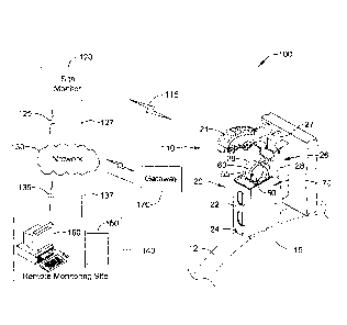
Figure 1 shows an illustrative view of an exemplary brush monitoring system
100 that
may include a brush holder assembly 110, a site monitor 120 and/or a remote
monitoring site
140 including a remote monitoring device 150, 160. In some cases, the brush
holder assembly
110 may substantially resemble a brush holder assembly as described in U.S.
Patent No.
7,034,430, entitled "BRUSH HOLDER APPARATUS, BRUSH ASSEMBLY, AND
METHOD". However, the illustrative brush monitoring system 100 may be amenable
to any
of various brush holder assembly configurations. Thus, the intention is that
the illustrative
brush monitoring system 100 may be used in conjunction with any desired brush
holder
assembly configurations of an electrical device, such as an industrial
electrical generator. For
example, the illustrative brush monitoring system 100 may be used with brush
holder
assemblies, brush holders and/or brushes disclosed in U.S. Patent Nos.
6,731,042; 5,753,992;
5,621,262; 5,463,264; 5,397,952; and 5,256,925.
The brush holder assembly 110, for example as shown in Figure 1, may include a
brush holder 22, such as a brush box, surrounding a brush 24 on several sides
and including a
plurality of guiding surfaces for guiding linear or longitudinal movement of
the brush 24. In
some embodiments, the brush holder 22 may not take on the form of a box, but
may include
one or a plurality of guiding surfaces, such as channels, posts or columns,
abutting and/or
encompassing one or more sides of the brush 24 and/or extending into or
through the brush 24,
or a portion thereof, for guiding linear or longitudinal movement of the brush
24.
6
CA 3020927 2018-10-16
The brush holder 22 may be secured to a mounting beam 26 configured and
adapted to
be mounted to another structure, such as a mounting block 70. The brush holder
assembly 110
may be configured to place the brush 24 in contact with a conductive surface
12, such as a
surface of a rotating component 15 of an electrical machine, such as a
collector ring, a slip
ring, or a commutator, and conduct current therefrom. The brush 24 may extend
from the
lower edge of the brush holder 22 such that a wear surface of the brush 24
engages the
conductive surface 12. The mounting beam 26 may include an over-center
engagement
mechanism, a slotted or channeled engagement mechanism for sliding engagement,
or other
mechanism for easily engaging and disengaging the brush 24 from a conductive
surface 12. In
other embodiments, the brush holder assembly may include a brush holder
rigidly mounted to
another structure holding the brush holder stationary, or mounted to another
structure in any
desired arrangement. For example, in some embodiments the brush holder may be
bolted or
welded to a stationary structure. Some such brush holders are disclosed in
U.S. Patent Nos.
6,731,042; 5,753,992; 5,621,262; 5,463,264; 5,397,952; and 5,256,925.
As shown in Figure 1, the mounting beam 26 may include an upper beam member 27
and a lower beam member 28 hingedly or pivotedly coupled to one another. When
the upper
beam member 27 and the lower beam member 28 are aligned with one another
(e.g., the
longitudinal axis of the upper beam member 27 is parallel with the
longitudinal axis of the
lower beam member 28), the brush holder 22 may be considered to be in an
engaged, or
locked, position such that the brush 24 may be contiguous with or in contact
with the
conductive surface 12. When the upper beam member 27 is tilted from the lower
beam
member 28 (e.g., the longitudinal axis of the upper beam member 27 is oblique
to the
longitudinal axis of the lower beam member 28), the brush holder 22 may be
considered to be
in a disengaged, or unlocked, position such that the brush 24 may be non-
contiguous with,
spaced from, or otherwise not in direct electrical contact with the conductive
surface 12. The
mounting beam 26 may be removably coupled to the mounting block 70 during
operation. In
some embodiments, the mounting beam 26 may slidably engage with, interlock
with, or
otherwise be removably coupled to the mounting block 70. The mounting block 70
may be
coupled to, secured to, or otherwise extend from another structure which
maintains the
mounting block 70 stationary with respect to the conductive surface 12, for
example.
7
CA 3020927 2018-10-16
In some embodiments, a handle 21 may be attached to the brush holder 22 to
facilitate
engagement and disengagement of the brush 24 from the conductive surface 12.
For example,
the handle 21 may be attached to the upper beam member 27 such that movement
of the
handle 21 actuates (e.g., pivots, slides, releases) the upper beam member 27
relative to the
lower beam member 28. The handle 21 may be a removable handle or the handle 21
may be
permanently attached to the upper beam member 27 or another portion of the
brush holder 22.
Also illustrated in Figure 1 is a spring 29, such as a constant force spring,
which
provides tension to the brush 24 to bias the brush 24 toward and in contact
with the conductive
surface 12. The spring 29 may be attached to a portion of the brush holder 22
or the mounting
beam 26 of the brush holder assembly 110, for example. In some embodiments,
the spring 29
may extend along one side surface of the brush 24 between the brush 24 and the
mounting
beam 26 of the brush holder assembly 110.
The brush holder assembly 110 may further include a wear state monitor 50 and
a
flexible sensor 60, wherein the wear state monitor 50 may be communicatively
coupled to the
flexible sensor 60. For example, the wear state monitor 50 may receive a
signal representative
of the position and/or movement of the brush 24. In some cases, the wear state
monitor 50
may be positioned adjacent to the spring 29. For example, the wear state
monitor 50 may be
mounted adjacent a surface of the spring 29 or otherwise with the spring 29,
such as within a
coil formed by the spring 29, as shown in Figure 3. The wear state monitor 50
may include
one or more indicators 55 to communicate the physical status of the brush 24,
the conductive
surface 12, or both. In some cases, the indicators 55 may include one or more
light emitting
diodes (LEDs), a speaker, or a combination of LEDs and/or speakers for
communicating wear
state information to a user. In some cases, the wear state monitor 50 may be
positioned
adjacent to a surface of a component of the brush holder assembly 110,
different than the
spring 29. For example, the wear state monitor 50 may be positioned on or
adjacent to the
brush holder 22, the lower beam member 28, the upper beam member 27, on or
adjacent to
one or more shunts of the brush holder assembly 110, and/or on or adjacent to
the handle 21 of
the brush holder assembly 110. In some cases, the wear state monitor 50 may be
permanently
and/or removably incorporated into a portion of the handle 21 or other
component of the brush
holder assembly 110.
8
CA 3020927 2018-10-16
The flexible sensor 60 may also be positioned adjacent to the spring 29, such
that a
movement of the brush 24 may cause the flexible sensor 60 to flex or otherwise
change shape.
For exam'ple, a proximal end of the flexible sensor 60 may be attached to a
portion of the
brush holder 22 or the mounting beam 26 of the brush holder assembly 110 and a
distal end
may be attached to and/or communicatively coupled to the wear state monitor
50. In some
cases, the flexible sensor 60 may be attached to, embedded in, in contact with
the spring 29
and track or follow the movement of the brush 24. For example, the flexible
sensor 60 may be
affixed to a surface (e.g., an inner surface, an outer surface, etc.) of the
spring 29. In another
example, the flexible sensor 60 may be positioned adjacent to the spring 29.
As such, any
movement of the flexible sensor 60 may directly correspond to movement of the
brush 24.
For example, a signal corresponding to the resistance value of the flexible
sensor 60
may be equivalent, proportional, or otherwise representative of the linear or
longitudinal
movement, vibration and/or diminution of the brush 24. In some cases, the wear
state monitor
50 may associate a steady-state resistance value of the flexible sensor 60
with a wear state of
the brush 24 and/or a transient resistance value with a wear state of the
conductive surface 12
and/or the rotating component 15. The steady state resistance value of the
flexible sensor 60
may correspond to a value obtained over one or more revolutions of the
rotating component 15
and may correspond to the position of the upper surface of the brush 24
relative to the
conductive surface 12 of the rotating component 15. In some cases, the
transient resistance
value of the flexible sensor 60 may correspond to a value obtained over at
least a portion of a
revolution of the rotating component 15, such as a resistance value caused by
a vibration of
the brush 24 caused by variances in the conductive surface 12 of the rotating
component 15.
The steady-state electrical value (e.g., a voltage level) may be compared to
one or more
predetermined threshold values to determine a wear state of the brush 24.
Similarly, the
transient electrical value may be associated with a vibration of the brush 24
and may be
monitored and/or compared to one or more predetermined thresholds to determine
a wear state
of the conductive surface 12 of the slip ring or other rotating component of
the electrical
machine.
The flexible sensor 60 may have an electrical resistance that varies based on
a radius of
curvature of the flexible sensor 60 and may produce a signal (e.g., a voltage
based signal, a
current based signal, etc.) corresponding to the electrical resistance of the
flexible sensor 60.
9
CA 3020927 2018-10-16
In some cases, the radius of curvature of the flexible sensor 60 may be
associated with a
deflection of the spring 29 providing a force to engage the carbon brush with
a rotating
component of the electrical machine. The electrical resistance of the flexible
sensor 60 may be
used with other electrical components to provide a signal representative of
the electrical
resistance of the flexible sensor 60. For example, the resistance of the
flexible sensor 60 may
be used as a component in a voltage divider circuit that is configured to
provide a voltage
signal that corresponds to the variable resistance of the flexible sensor 60.
In other cases, an
electrical circuit associated with the flexible sensor 60 may be configured to
provide a current
signal representative of the variable electrical resistance of the flexible
sensor 60.
In some cases, the brush monitoring system 100 may include a site monitor 120
that
may be positioned near the electrical machine to monitor the wear state of one
or more brush
holder assemblies 110 and/or the wear state of the slip ring or other rotating
component of the
electrical machine. The site monitor 120 may be capable of monitoring the wear
states of the
brush 24 of the brush holder assembly 110. In some cases, the site monitor 120
may be
capable of monitoring the movement of the brushes 24 of two or more brush
assemblies 110
associated with one or more electrical machines. For example, the site monitor
120 may be
communicatively coupled to one or more wear state monitors 50 associated with
a particular
electrical machine, such as the wear state monitor 50 of the brush holder
assembly 110 via a
communication link 115 (e.g., a wireless link). The site monitor 120 may be
configured to
receive processed data and/or raw data providing information about the wear
state of the brush
24 and/or the rotating component 15. For example, the site monitor 120 may
receive
information about a comparison between a value received from the flexible
sensor 60 and one
or more predetermined thresholds, the value received from the flexible sensor
60, or both. In
some cases, the communication link 115 may include a radio frequency (RF)
communication
link, an audio-based communication link (e.g., an ultrasonic communication
link), and/or an
optical communication link (e.g., an infrared (IR) communication link, a
visible light
communication link, etc.). In some cases, the site monitor 120 may be
configured to predict
or determine an estimated projection of a condition of the brush 24 into the
future.
In some cases, the wear state monitor 50 may be configured to communicate the
wear
state information about the brush 24 and/or the rotating component 15 of the
electrical
machine to the site monitor 120 using a predetermined schedule (e.g., once per
hour, once per
CA 3020927 2018-10-16
day, twice per week, etc.). In some cases, the wear state monitor 50 may
provide the wear
state information about the brush 24 and/or the rotating component 15 of the
electrical
machine to the site monitor 120 in response to a command received from the
site monitor 120
and/or the remote monitoring device 150, 160.
The site monitor 120 may output an indication of the condition and/or
projected
condition of the brush 24. In some cases, the indication may be configured to
alert an
operator, technician and/or other personnel that the brush 24 and/or the
rotating component 15
are sufficiently worn and/or needs to be replaced, the brush 24 and/or the
rotating component
15 are damaged, failure has occurred or is imminent, or other maintenance or
inspection may
need to be performed. In some embodiments, the indication may be used for
scheduling
maintenance or inspection, sending personnel to perform maintenance or
inspection, ordering
and/or scheduling distribution/delivery of a replacement brush or other part,
routing
maintenance personnel and/or product delivery to a specified location, or
arranging for other
notification and/or scheduling tasks be performed.
The brush monitoring system 100 may also be used to identify and/or notify
other key
maintenance, failure of the brush holder assembly 110 and/or other anomalous
conditions. For
example, incidents of excess heating, arcing or excess vibration, which may
indicate a need to
perform maintenance and/or disrupt operation of the electrical equipment, may
be identified
and/or assessed by one or more components of the brush monitoring system 100.
The wear
state monitor 50, the site monitor 120 and or the remote monitoring device
150, 160 may carry
out an appropriate response to respond to an identified anomalous condition in
an attempt to
rectify the anomalous condition. In some cases, an operator may carry out an
appropriate
response to respond to an anomalous condition identified with the brush
monitoring system
100 in an attempt to rectify the anomalous condition.
In some cases, the site monitor 120 may be communicatively coupled by a
wireless
link 125 and/or wired link 127 to a network 130. The site monitor 120 may be
capable of
communicating information about the wear state of one or more brushes to a
remote
monitoring device 150, 160 at a remote monitoring site 140 via the network 130
and one or
more wired 137 and/or wireless 135 communication links. The wired link 127,
137 and/or
wireless link 125, 135 communication links may be configured to operate using
one or more
standardized communication protocols (e.g., Ethernet, Ethernet/IP, BACnet,
Modbus,
11
CA 3020927 2018-10-16
LonWorks, etc.), or proprietary communication protocols. Examples of a remote
monitoring
system are described in U.S. Patent No. 7,705,744, entitled "MONITORING
SYSTEMS AND
METHODS FOR MONITORING THE CONDITION OF ONE OR MORE COMPONENTS
OF AN ELECTRICAL DEVICE", and U.S. Patent Application No. 11/752,965 entitled
"BRUSH HOLDER ASSEMBLY MONITORING APPARATUS, ASSEMBLY, SYSTEM
AND METHOD" and has the U.S. Patent Publication No. 2008/0291273. The remote
monitoring site 140 may include one or more remote monitors, such as a
personal computer
160, a workstation, a laptop, a tablet 150, a smart phone or the like, for
collecting data and/or
analyzing data received from one or more user sites.
The remote monitoring devices and/or site monitor 120 may be integrated into a
maintenance program for a brush holder assembly 110, such that the site
monitor 120 may be
configured to monitor at least a condition of one or more components of the
brush holder
assembly 110. To do so, the remote monitors and/or the site monitor 120 may be
configured
to identify each brush holder assembly 110 on a particular machine or at a
particular site
and/or store an installation date and any servicing dates for each brush
holder assembly 110.
In some cases, one or more parameters received from the wear state monitor 50
associated
with a brush holder assembly 110 may be monitored over time to determine
trending
information about a brush 24 and/or a rotating component 15 of the electrical
machine. For
example, the site monitor 120 and/or the remote monitors may determine trend
information,
that may include an average lifetime for a brush 24 installed in a particular
brush holder
assembly 110 and/or for a particular installation position on an electrical
machine. The site
monitor 120 and/or the remote monitors may be configured to store information
about the
position of a brush (e.g., a resistance value of the flexible sensor 60), when
the brush holder
assembly 110 is first installed on an electrical machine. By monitoring the
initial position
each time a brush 24 is replaced in the brush holder assembly 110, information
may be
gathered about a wear state of the rotating component 15. For example, a slip
ring, or other
rotating component of the electrical machine, may have an initial outer
diameter measurement.
Over time, with wear including normal wear and/or due to environmental
conditions (e.g.,
humidity, temperature, contaminants including abrasives, etc.) a wear state
associated with the
thickness and/or outer diameter of the rotating component 15 may be measured
and/or
predicted. In some cases, preventative measures to improve the lifetime of the
brush 24 and/or
12
CA 3020927 2018-10-16
the rotating component 15 may be obtained by analysis of the information
received from the
one or more wear state monitors 50. For example, a user may be advised to
adjust one or
more environmental conditions for a space near the electrical machine, such as
a temperature,
a humidity level and/or a contaminant level.
Figures 2A and 2B are perspective views 200, 250 of the illustrative wear
state monitor
50 of Figure 1. The wear state monitor 50 may include a body 210, one or more
ribs 220, an
opening 225 to facilitate an electrical connection to the flexible sensor 60,
one or more
communication interfaces 230, and one or more indicators 240. In some cases,
the wear state
monitor may include a user interface 260. The body 210 may be generally
cylindrical, or
other such shape designed to facilitate integration into a brush holder
assembly 110 or other
mounting location within the brush holder assembly 110. For example, the wear
state monitor
50 may be configured to be associated with the spring 29 of the brush holder
assembly 110, as
shown in Figure 3. The body 210 of the wear state monitor 50 may be designed
to be captured
within a coiled portion of the spring 29. The ribs 220, or other similar
structure, may be used
to ensure the wear state monitor 50 remains mounted within the coil. The ribs
220 may be
removable, or otherwise configurable, to allow the wear state monitor 50 to be
mounted within
a coil of two or more different sized springs. For example, the removable
and/or configurable
ribs, such as the ribs 220, may allow the wear state monitor 50 to be mounted
within a spring
having a first width and a first coil diameter and/or a spring having a second
width and/or a
second diameter.
The opening 225 of the wear state monitor 50 may be used to facilitate a
connection
with the flexible sensor 60. For example, the opening 225 may allow access to
an electrical
connection, such as a screw terminal. The opening 225 may have a shape
corresponding to a
cross-sectional shape of the flexible sensor (e.g., a slot), or may be another
shape (e.g., a
circular opening, a rectangular opening, etc.) designed to accommodate an
electrical
connection to the flexible sensor 60.
As discussed above, the wear state monitor 50 may be configured to determine
one or
more wear states of the brush 24 and/or the rotating component 15 of the
electrical machine
using information obtained using the flexible sensor 60 (e.g., a variable
resistance, a voltage
signal, a current signal, etc.). In some cases, the wear state monitor 50 may
include one or
more electrical connections for providing an electrical connection to the
flexible sensor 60.
13
CA 3020927 2018-10-16
The electrical connections may be located within an interior space of the wear
state monitor
50, such that the flexible sensor 60 may be integrated with the wear state
monitor 50 and may
extend through the opening 225 to provide a direct electrical connection
between the wear
state monitor 50 and a portion of the flexible sensor 60. In some cases, one
or more wires
(e.g., individual wires, a shielded twisted-pair cable, a ribbon cable, etc.)
may extend through
the opening 225 to facilitate an electrical connection to the flexible sensor
60. The electrical
connections may be formed as a permanent and/or semi-permanent electrical
connection,
using solder, a conductive epoxy, screw terminals, spring terminals, a
compression fitting, a
snap fitting, a crimp fitting, or the like. The electrical connections may be
accessible to a user
with or without disassembly of at least a portion (e.g., a cover) of the wear
state monitor 50.
For example, a user may be capable of accessing a terminal via the opening 225
and/or by
removing a removable cover that may comprise an end 201, 203 of the wear state
monitor 50.
The cover may be secured by a threaded connection, a snap-fit connection
and/or one or more
connectors (e.g., screws). In some cases, the exterior housing of the wear
state monitor 50
may be configured in two or more sections that may be hingedly connected
(e.g., a "clam
shell" configuration), or otherwise movable relative to one another. In such
cases, when the
wear state monitor 50 is located within the coiled portion of the spring 29
(e.g., a helical
spring), the force provided by the spring 29 may facilitate a compression
connection or snap
fit connection for the hingedly connected sections of the housing of the wear
state monitor 50.
Also, the force provided by the spring 29 may also facilitate a compression
connection or
other pressure based electrical connection between the wear state monitor 50
and the flexible
sensor 60. In some cases, the flexible sensor 60 may be electrically connected
to the wear
state monitor using an interface (e.g., one or more terminals, one or more
bonding pads, etc.)
located at an end 201, 203 and/or on the body 210 of the wear state monitor
SO. In some
cases, an externally accessible electrical connection interface for the
flexible sensor 60 may
extend above the surface of the wear state monitor 50, or may be recessed in a
cavity formed
into the exterior surface of one or more of the ends 201, 203 or the body 210.
The wear state monitor 50 may be capable of communicating information about
the
wear state of the brush 24 and/or the rotating component 15 to a user via the
communication
interface 230 and/or the indicators 240. The communication interface 230
and/or the
indicators 240 may be located at the same or different surface of the wear
state monitor 50.
14
CA 3020927 2018-10-16
For example, the communication interface 230 may be located at a first end 201
of the wear
sensor and the indicators 240 may be located at a second end 203 of the wear
state monitor,
but this is not required. The communication interface 230 may be capable of
transmitting
information via one or more communication protocols using audio energy (e.g.
an ultrasonic
signal), radio frequency (RF) energy (e.g., an RF signal), and/or light energy
(e.g., an optical
signal, an infrared (IR) signal, etc.), or the like.
In some cases, the wear state monitor 50 may be capable of receiving messages
from
an external device, such as the site monitor 120 and/or a programming device
located at the
same site or at a remote location (e.g., a computer 150, a tablet 160, a smart
phone, etc.). The
messages may include commands, such as commands to send wear state information
about the
brush 24 and/or the rotating component 15, or commands for modifying
information used by
the wear state monitor 50. For example, a user may desire to modify one or
more thresholds
used to determine the wear state information of the brush 24 and/or the
rotating component 15,
and/or to reprogram the wear state monitor 50 by downloading instructions,
tables and/or the
like (e.g., compiled code). In some cases, the wear state monitor 50 may
include one or more
user interfaces 260 that may be used for programming or otherwise providing
information
about the location and/or function of the wear state monitor 50. For example,
a user may use
the user interface 260 as a programming interface to modify one or more
thresholds and/or to
reprogram the wear state monitor 50 rather than using the communication
interface 230. For
example, a user may connect a programming device via a cable or use one or
more memory
devices (e.g., a flash card, a universal serial bus (USB) drive, etc.) to
download and/or upload
information from the wear state monitor 50. In some cases, the user interface
260 may include
one or more switches (e.g. a dual inline package (DIP) switch, a rotary
position switch, etc.) to
associate the wear state monitor 50 with a particular brush assembly 110
and/or a particular
installed position at the electrical machine and/or at the customer site.
The indicators 240 may include one or more optical indicators (e.g. LEDs)
and/or one
or more audio indicators (e.g., a speaker) for providing an optical and/or
audible indication of
the wear state of the brush 24 and/or the wear state of the rotating component
15. For
example, indicators 240 of the wear state monitor 50 may include one or more
LEDs, wherein
the one or more light emitting diodes (LED) may be configured to emit light of
a first color
when the wear state monitor 50 determines a first wear state of the brush 24
and to emit light
CA 3020927 2018-10-16
of a second color when the wear state monitor 50 determines a second wear
state of the brush
24. In some cases, additional colors may be used to indicate additional wear
states of the
brush 24. The indicators may use the same and/or different ones of the one or
more LEDs to
indicate the wear state information of the rotating component 15. For example,
the one or
more LEDs may be configured to emit light of a third color when the wear state
monitor 50
determines a first wear state of the rotating component 15 and to emit light
of a fourth color
when the wear state monitor 50 determines a second wear state of the of the
rotating
component 15. In some cases, additional colors may be used to indicate
additional wear states
of the rotating component 15. In some cases, a first set of LEDs may be
configured to
provide wear state information about the brush 24 and a second set of LEDs for
indicating
wear state information about the rotating component 15
For example, the wear state monitor 50 may include one or more LEDs configured
to
emit light of a first color (e.g., green) when the wear state monitor 50
determines that the
brush 24 has an operational wear state, to emit light of a second color (e.g.,
yellow) when the
wear state monitor 50 determines that the brush 24 is approaching the
replacement wear state,
and to emit light of a third color (e.g., red) when the wear state monitor 50
determines that the
brush 24 has reached the replacement wear state. In some cases, the wear state
monitor 50
may be configured to illuminate a different number of LEDs and/or a pattern of
LEDs, of the
same or different colors, to indicate one or more particular wear state
conditions of the brush
24 and/or the rotating component 15.
In another example, the wear state monitor 50 may be configured to provide a
first
audible indication of the wear state of the brush 24 (e.g., an intermittent
tone) when the wear
state monitor 50 determines that the brush 24 is approaching the replacement
wear state, and
to provide a second audible indication of the wear state of the brush 24
(e.g., a different
intermittent tone, a tone at a different frequency, a steady tone, etc.) when
the wear state
monitor 50 determines that the brush 24 has reached the replacement wear
state.
Figure 3 shows an exploded perspective view of the brush holder assembly 110
in an
engaged position and including the illustrative wear state monitor 50 of
Figures 1 and 2. In
some cases, the brush holder assembly 110 may include an integral flexible
sensor 60 that may
be used for monitoring a wear state of the brush 24 and/or an associated
rotating component
15 of an electrical machine. The brush holder assembly 110 may include the
brush 24 (e.g. a
16
CA 3020927 2018-10-16
carbon brush) and a spring 29 associated with the brush 24. The spring 29 may
provide a
force to engage the brush 24 with a rotating component of an electrical
machine, such as a slip
ring, a commutator, and the like. For example, the spring 29 may include a
coil portion 310
that may be used to apply the force to the brush 24. The wear state monitor 50
may be
positioned adjacent to the spring 29. In some cases, the wear state monitor 50
may be
positioned substantially within the coil 310.
In some cases, the flexible sensor 60 may be positioned adjacent to the spring
29 such
that the changing bend radius of the spring 29 associated with the movement
and/or wear of
the brush 24 causes a corresponding bend radius on the flexible sensor 60. For
example, the
flexible sensor 60 may be affixed or otherwise positioned adjacent to a
surface of the spring
29. In another example, the flexible sensor 60 may be positioned adjacent to
an edge of the
spring 29.
Other configurations for positioning the flexible sensor 60 in relation to the
spring 29
and/or brush 25 may be contemplated. For example, a portion of the flexible
sensor 60 may
be affixed to one or more other components of the brush holder assembly 110
(e.g., the brush
holder 22, the handle 21, the upper beam member 27, the lower beam member 28,
and the
like). In such cases, a different portion of the flexible sensor 60 may be
communicatively
coupled to the wear state monitor 50 located in the coil portion 310 of the
spring 29 or other
location of the brush holder assembly 110. In some cases, the flexible sensor
60 may have a
first bend radius upon initial installation of the brush 24 that is less than
the bend radius after
the brush 24 is worn. In other cases, the flexible sensor 60 may have a first
bend radius upon
initial installation that is greater than the bend radius after the brush 24
is worn. In some
instances, the flexible sensor 60 may have a configuration such that the bend
sensor 60 does
not have a bend radius, such as when the bend sensor 60 is substantially
aligned along a plane.
For example, the bend radius of the flexible sensor 60 may have a positive
bend radius upon
installation and a negative bend radius after the brush is worn, or a negative
bend radius upon
installation and a positive bend radius after the brush is worn, or the bend
sensor may be
substantially aligned along a plane at initial installation or after a
particular amount of wear to
the brush 24. In some cases, two or more flexible sensors 60 may be used for
monitoring the
wear states of the brush 24 and/or the rotating component 15. The two or more
flexible
sensors 60 may be positioned adjacent to different portions of the spring,
such that a first
17
CA 3020927 2018-10-16
flexible sensor 60 may be used to monitor the wear state of the brush 24
and/or the rotating
component 15 over a first duration of time and a second flexible sensor 60 may
be used to
monitor the wear state of the brush 24 and/or the rotating component 15 over a
second
duration of time. The first and second durations of time may overlap in some
instances. In an
illustrative example, the first flexible sensor 60 may be at least partially
bent (e.g., positioned
near the coil of the spring 29) and the second flexible sensor 60 may be
significantly straight
(e.g., positioned near the lower beam member 28), such that the wear state
monitor 50 may be
configured to primarily or solely use information from the first flexible
sensor 60 during a
duration of time after installation of the brush assembly 110 on the machine,
a combination of
information received from both the first and second flexible sensors during a
second duration
of time during normal operation, and information received primarily or solely
from the second
flexible sensor at a third duration of time, such as a duration of time when
the brush 24 is
approaching a replacement wear state or is otherwise near a replacement wear
state.In some
cases, a sensor other than a flexible sensor having a variable resistance may
be contemplated
to obtain information about an amount of wear to the brush 24 and/or an amount
of wear to the
rotating component 15 in relation to a movement of the spring 29. Obtaining
information
about an amount of wear to the rotating component 15 includes obtaining
information about an
amount of wear to the surface 12 of the rotating component 15. In some cases,
one or more
wires may be positioned adjacent to the spring 24. For example, a portion of
one or more
wires may be affixed to the spring 24. In some cases, an opening in a portion
of an insulating
layer around the one or more wires may be present to expose a portion of the
wire. In such
cases, the exposed and/or un-insulated portion of the wire may contact another
surface (e.g., a
surface of the spring 29, a surface of the brush 24, or another surface
associated with the brush
assembly 110), which may cause the wire to conduct electricity and/or stop
conducting
electricity. In some cases a first wire may be positioned to indicate a known
wear state of the
brush 24, such as an initial wear state condition, a wear state approaching a
replacement wear
state condition of the brush 24, and/or a replacement wear state condition of
the brush 24. In
some cases, a second or additional wire may be positioned to indicate another
wear state of the
brush 24 different from the first wear state. For example, a first wire may be
used to indicate a
wear state approaching a replacement wear state, and a second wire may be used
to indicate a
replacement wear state of the brush 24. In some cases, the wire may be
associated with one or
18
CA 3020927 2018-10-16
more resistors, and/or other electrical components. In such cases, as the wear
state of the
brush 24 changes, different ones of the one or more electrical components
(e.g., transistors,
LEDs, resistors, etc.) may be included in an electrical circuit. For example,
a first resistance
value may be associated with a first particular wear state and a second
resistance value may be
associated with a second particular wear state. In some cases, the wear state
monitor 50 may
include a sensor or other device to at least partially identify a vibration or
other movement
corresponding to a wear state of the rotating component 15. For example, an
acceleration
and/or a pressure sensor may be associated with the wear state monitor 50 and
information
received from the acceleration and/or the pressure sensor may be used to
identify a
characteristic (e.g., a magnitude, a frequency, etc.) of a vibration of the
brush 24. The wear
state monitor 50 may use this information in addition to or in place of
information received
from the flexible sensor 60, such as a bend sensor, or other sensor (e.g., a
temperature sensor,
a humidity sensor, etc.) to determine whether the wear state of the rotating
component 15 is
approaching a maintenance wear state or has reached a required maintenance
wear state.
The wear state monitor 50 may be communicatively coupled to the flexible
sensor 60
to receive a signal corresponding to the wear state of at least one of the
brush 24 and the
rotating component 15. The wear state monitor 50 may be configured to
determine the wear
state of the brush 24 and/or the rotating component 15 using a comparator by
comparing the
signal received from the flexible sensor 60 to at least one predetermined
threshold. The wear
state monitor 50 may provide the determined wear state information about the
brush 24 and/or
the rotating component 15 to a user via an indicator provided on the wear
state monitor 50
and/or a communication circuit capable of communicating to an external device,
such as the
site monitor 120, via a communication link.
Figure 4 is a block diagram representation of the illustrative wear state
monitor 50 of
Figures 1-3. In an example, the illustrative wear state monitor 50 may be
communicatively
coupled to a sensor, such as the flexible sensor 60 to obtain information
about the wear state of
the brush 24 and/or the rotating component of the electrical machine. In this
illustrative
embodiment, the wear state monitor 50 may include one or more of an
input/output block (I/O
block) 410, a signal conditioning circuit 420, a comparison circuit 430 (e.g.,
a comparator), a
processor 440 (e.g. a microprocessor, a microcontroller, etc.), a user
interface 450, a
communication circuit 470, a memory 480 and/or a data port 490. In some cases,
the wear
19
CA 3020927 2018-10-16
state monitor 50 may include a power source 460, such as a battery, a
capacitor, or both. In
some cases, the battery may be rechargeable and/or replaceable. In some cases,
the wear state
monitor 50 may include energy harvesting capability, such that the power
source 460 may
receive energy and/or may be recharged by one or more energy harvesting
technologies. For
example, illustrative energy harvesting technologies may include a kinetic
(e.g., vibrational)
energy harvester (e.g., a piezoelectric vibration energy harvester, a magneto-
inductive
vibration energy harvester, etc.), a photovoltaic energy harvester capable of
harvesting energy
indoors and/or outdoors, a piezoelectric energy harvester, a thermal energy
harvester, a wind
energy (e.g., microturbine) harvester, and/or an ambient radiation (e.g. radio
frequency)
energy harvester.
In some cases, in addition to or instead of the power source 460, the wear
state monitor
50 may include one or more connectors and/or terminals= capable of receiving
power from a
source separate from the wear state monitor 50. In such cases, the wear state
monitor 50 may
be configured to receive power from an external power source when the brush
holder
assembly 110 is installed on the electrical machine. For example, an
electrical circuit to the
wear state monitor 50 may be completed when the brush holder assembly 110 is
coupled to the
mounting block 70 such that electrical power may pass from a power source
through the
mounting block 70 to the wear state monitor 50. In such a configuration,
electrical power may
be automatically provided to the wear state monitor 50 when the brush holder
assembly 110 is
mounted onto the mounting block 70 of the electrical machine, and electrical
power to the
wear state monitor 50 may be discontinued when the brush holder assembly 110
is removed
from the mounting block 70. In some cases, the I/O block 410 may include one
or more
connectors 415 (e.g., screw terminals, spring terminals, etc.) for connecting
the flexible sensor
60 to the wear state monitor 50. In some cases, the I/O block 410 may be
located within the
wear state monitor 50 or may be positioned on or near an external surface of
the wear state
monitor 50. For example, the I/O block 410 may be positioned within a cavity
within the wear
state monitor 50 and accessible via an opening and/or a removable cover. A
signal received
from the flexible sensor 60 may be conditioned by the signal conditioning
circuit 420.
The signal conditioning circuit 420 may be configured to perform filtering,
amplification, buffering, and/or other adjustments to the amplified pressure
indicating signal.
In some cases, the signal conditioning circuit 420 may include one or more
discrete
CA 3020927 2018-10-16
components (e.g., resistors, transistors, capacitors, inductors, diodes, etc.)
and/or integrated
circuits (e.g., operational amplifiers, buffers, ASICs, etc.). In some cases,
the signal
conditioning circuit 420 may include one or more filters 422. The filters 422
may be
implemented as a combination of integrated or discrete elements, such as a
resistor and a
capacitor configured as a series RC network (e.g., a low-pass filter).
Although a first order
low-pass filter may be used, it is contemplated that any combination of analog
or digital filters
can be used, including one or more high pass filters, low pass filters, band
pass filters, notch
filters, passive filters (e.g., having "T" sections, "7r" sections, etc.),
active filters (e.g.,
Chebyshev filter, Butterworth filter, etc.), IIR filters, FIR filters, and/or
any other suitable
filter or filter combination.
The signal received from the flexible sensor 60 may then be compared to one or
more
predetermined thresholds using the comparison circuit 430. In some cases, the
threshold for
the one or more thresholds may be set using one or more discrete electrical
components, such
as one or more resistors, capacitors, inductors, diodes, transistors, and/or
integrated circuits,
such as a comparator and/or a processor. In some cases, the processor 440 may
read the
threshold from a memory 480 and/or compute the threshold using one or more
instructions
stored in the memory 480. In some cases, the specified threshold may be fixed
at a pre-
determined level. In other cases, the specified threshold may be configurable
and/or
adaptable, as desired. For example, the one or more thresholds may be
configurable by a user
during a calibration procedure before and/or after the wear state monitor 50
is installed in a
brush holder assembly 110. During an illustrative calibration procedure, the
user may obtain
one or more steady-state values from the flexible sensor 60 after the flexible
sensor 60 is
installed in the brush holder assembly 110. For example, the obtained values
may correspond
to a first position of the brush 24, such as an engaged position when the
brush 24 has
approximately no wear and a second position corresponding to a brush position
approximating
a position when the brush 24 has a predetermined amount of wear (e.g.,
approaching the
replacement threshold, maximum allowable wear, etc.). Calibration may be
important due to
one or more mechanical and/or electrical differences between particular brush
assemblies. In
some cases, a user may communicate a threshold value via a communication
interface, such as
the communication circuit 470, the user interface 450 (e.g., using one or more
switches 454
21
CA 3020927 2018-10-16
and/or potentiometers 458), and or the data port 490, such as from an external
memory device
(e.g., a flash memory device, etc.).
The processor 440 may operate using an algorithm for determining a wear state
indication of at least one of the brush 24 and the rotating component 15
and/or communicates
one or more indication of the wear state of the brush 24 and/or rotating
component 15 to a
user. The processor 440 may, for example, operate using an algorithm that
causes the wear
state monitor 50 to obtain information corresponding to a bend radius of the
flexible sensor 60
continuously or at predetermined intervals. In some cases, wear state monitor
50 may include
a timer 445 and/or an analog to digital converter (ADC) 447. The timer 445
and/or the ADC
447 may be integral to the processor 440 or may be provided as a separate
component. In
some cases, one or more components and/or functionality of the signal
conditioning circuit
420 and/or the comparison circuit 430 may be incorporated into the
instructions processed by
the processor 440.
The memory 480 of the illustrative wear state monitor 50 may be in
communication
with the processor 440. The memory 480 may be used to store any desired
information, such
as the aforementioned control algorithm, threshold values, schedule times,
sampling times,
trending information, and the like. The memory 480 may be any suitable type of
storage
device including, but not limited to, RAM, ROM, EPROM, flash memory, a hard
drive, and/or
the like. In some cases, the processor 440 may store information within the
memory 480, and
may subsequently retrieve the stored information.
In the illustrative embodiment of Figure 4, the user interface 450 may be any
suitable
user interface that permits the wear state monitor 50 to display and/or
solicit information. In
some cases, the user interface 450 may accept one or more user interactions
with the wear
state monitor 50 and/or may permit the wear state monitor 50 to display, or
otherwise convey,
information about the wear state of the brush 24 and/or the rotating component
15. For
example, the user interface 450 may include one or more indicators, such as
LEDs 452 or
speakers 456, capable of providing the indication of the determined wear
states to the user.
The LEDs 452 may include one or more LEDs 452 capable of emitting one or more
colors, the
colors and/or the lack of colors being representative of a corresponding wear
state. For
example, an unlit LED and/or an LED emitting a green light (optional) may
indicate an
operational or "good" wear state. an LED emitting a yellow light may indicate
a wear state
22
CA 3020927 2018-10-16
where the associated component may be approaching a replacement wear state,
and an LED
emitting a red light may indicate a replacement wear state. The listed color
choices are merely
representative and other colors and/or combinations of colors may be
contemplated. In some
cases, the user interface 450 may be configured to illuminate a different
number of LEDs 452
and/or a pattern of LEDs 452 to indicate one or more particular wear state
conditions of the
brush 24 and/or the rotating component 15. In some cases, a reflective surface
(e.g., the
polished brush box of the brush holder 22, a separate reflector, etc.) may be
used to direct
and/or amplify light emitted by the one or more LEDs.
In some cases, the wear state of the brush 24 and/or rotating component 15 may
be
indicated by the user interface 450 via the speaker 456. The speaker 456 may
be used to emit
an audible indication, such as a specified tone for a specified duration, for
one or more wear
states of the brush 24 and/or the rotating component 15.
In some cases, the user interface 450 may include one or more components to
allow a
user to input information about the wear state monitor 50 (e.g., a
communication address, an
installed location, etc.), information about the flexible sensor 60 and/or
brush holder assembly
110 (e.g., calibration information, threshold information, etc.), or other
information about the
brush monitoring system 100. For example, the user interface 450 may include
one or more
switches 454 that may be used to assign a communication address or other
identification
information, to a particular wear state monitor 50, assign a communication
channel and/or
frequency for communication via the communication link 115, specifying a
monitoring
schedule, and/or adjust a threshold by, for example, adding and/or removing a
resistor network
to adjust a voltage divider network. For example, a user interface 450 may
include one or
more groups of switches 454, where a first portion of switches 454 may be used
to assign a
site address, a second portion of the switches 454 may be used to assign an
electrical machine
number and a third portion of the switches 454 may be used to assign a brush
assembly
number or identify a location of the brush assembly 110. In some cases, the
user interface 450
may include one or more potentiometers and/or variable resistors that may be
used to adjust a
threshold, such as during a configuration process. These user interface
components are merely
illustrative and other components may be contemplated.
In some cases, user interface 450 may include a display 458 and one or more
buttons
459 for entering information, such as by navigating one or more menu options.
The display
23
CA 3020927 2018-10-16
458 may be any suitable display. In some instances, a display 458 may include
or may be a
liquid crystal display (LCD), and in some cases a fixed segment display or a
dot matrix LCD
display. If desired, user interface 450 may be a touch screen LCD panel that
may operate both
display 458 and data entry functions. In some instances, the display 458 may
be adapted to
solicit values for a number of operating parameters and/or to receive such
values, but this is
not required. In some cases, the user may be capable of entering at least a
portion of the
identification information (e.g., a site number, a machine number, a brush
assembly number)
using the touch screen display, the keyboard, the buttons 459 or other means
of inputting the
numerical and/or textual information
In many cases, when a diagnostic limit, such as a predetermined threshold, has
been
violated, the processor 440 may be configured to indicate to the user that a
diagnostic fault has
occurred. This may be accomplished in any of a variety of ways. For example,
if the
processor 440 has determined that a diagnostic limit has been violated, and a
diagnostic fault
has occurred, the processor 440 may cause a user alert to be indicated by the
user interface
450. In some cases, the processor 440 may process instructions to alert the
user to a particular
wear state only after a predetermined number of threshold violations and/or
that a threshold
violation exceeds a particular duration are detected by the processor 440. For
example, the
processor 440 may be programmed to indicate a wear state of the brush 24 after
a particular
threshold value has been met for at least a predetermined threshold (e.g., 5
seconds, 30
seconds, 1 minute, etc.). Similarly, the processor 440 may be programmed to
indicate a wear
state of the rotating component 15 after a particular threshold (e.g., a
replacement threshold)
has been exceeded for a specified number of times (e.g., ten times, fifteen
times, etc.) within a
particular duration (e.g., 30 seconds, 1 minute, etc.) and/or a specified
number of revolutions
of the rotating component (e.g., 10 revolutions, 20 revolutions, etc.). In
some cases, the user
alert may be an audible tone from the speaker 456 and/or a simple text string
displayed on a
display of the user interface 450 which may describe the nature of the
violation that has
occurred. In other instances, the processor 440 may provide some visual
indication to alert the
user that a fault has occurred. Such visual indication may include a colored,
flashing or
otherwise visible indication provided on the user interface 450. In still
other instances, the
processor 440 may be configured to provide information to another device, such
as the site
monitor 120 or the remote monitoring device 150, 160. One or more of the site
monitor 120
24
CA 3020927 2018-10-16
or the remote monitoring device 150, 160 may provide the information to a user
via a visual
indication, an audible indication, an email, an instant message, a text
message or some other
message to a user to alert the user of the wear state of the one or more
components of the
brush holder assembly 110. Such information may be provided via an internet
gateway 170 or
other device that is adapted to communicate over the internet or other wide
area network, a
local area network, and the like. For example, the internet gateway 170 may be
configured to
communicate with the network 130, and/or an industrial control system. Such an
alert may be
provided to the user even when the user is away from the site in which the
brush monitoring
system 100 is located.
In addition to the user interface 450, the wear state monitor 50 may be
capable of
communicating information about the wear state of the brush 24 and/or the
rotating
component 15 to a user via the communication circuit 470. The information
about the wear
state of the brush 24 and/or the rotating component 15 may be associated with
information
identifying one or more of a particular site, a particular electrical machine
and/or a particular
brush assembly associated with the brush 24 and/or the rotating component 15.
In some cases,
the communication circuit 470 may include a communication port (e.g., a
speaker 472, a
transceiver 474, etc.) that may be used to communicate with the site monitor
120 via the
communication link 115. One or more communication protocols may be used by the
wear
state monitor 50 to communicate wear state information associated with the
brush holder
assembly 110 to the site monitor 120. The communication circuit 470 may
include a chipset
capable of communicating via one or more communication link technologies such
as by using
audio energy (e.g. an ultrasonic signal), radio frequency (RF) energy (e.g.,
an RF signal),
and/or light energy (e.g., an optical signal, an infrared (IR) signal, etc.),
or the like. In some
cases, the communication circuit 470 may be capable of communicating via one
or more other
wireless technologies such as BluetoothTM, Wi-Fi, Zigbee or any other wireless
protocol. In
some cases, the communication circuit 470 may be configured to communicate via
one or
more wired interfaces, but this is not required. For example, the
communication circuit 470
may include a wired port such as a serial port, an ARCNET port, a parallel
port, a serial port, a
CAT5 port, a USB (universal serial bus) port, and/or the like. In some cases,
the
communication circuit 470 may use one or more communication protocols, such as
Ethernet,
CA 3020927 2018-10-16
BACNet, LONtalk, DeviceNet, ControlNet, Profibus, etc., that may be used via a
wired
network or a wireless network.
In some cases, as illustrated in Figure 4, the wear state monitor 50 may
optionally
include a data port 490. Data port 490 may be a wireless port such as a
BluetoothTM port or
any other wireless protocol. In other cases, data port 490 may be a wired port
such as a serial
port, a parallel port, a CAT5 port, a USB (universal serial bus) port, and/or
the like. In some
instances, data port 490 may be a USB port and may be used to download and/or
upload
information from a USB flash drive or some other data source. Other remote
devices may also
be employed, as desired. The
data port 490 may be configured to communicate with
processor 440 and may, if desired, be used to upload information to processor
440 and/or
download information from the processor 440. Information that can be uploaded
and/or
downloaded may include, for example, values of thresholds and/or timing
information. In
some instances, the data port 490 may be used to upload previously-created
configuration
information of the wear state monitor 50 and/or the flexible sensor 60,
thereby hastening the
configuration process. In some cases, data port 490 may be used to download a
configuration
that has been created using a particular wear state monitor 50 and/or flexible
sensor 60 so that
the configuration may be transferred to other similar wear state monitors 50,
hastening their
programming process. In some cases, the data port 490 may be used to upload
and/or
download information pertaining to wear state trends of the brush 24 and/or
the rotating
component 15, if desired.
In some cases, data port 490 may be used to download data stored within the
memory
480 for analysis. For example, data port 490 may be used to download a wear
state log
associated with the brush 24 and/or the rotating component or parts thereof to
a removable
device such as a USB memory stick (also sometimes referred to as a thumb drive
or jump
drive), personal computer, laptop, iPADO or other tablet computer, PDA, smart
phone, or
other remote device, as desired. In some cases, the data may be convertible to
an MS
EXCEL , MS WORD , text, XML, and/or Adobe PDF file, but this is certainly not
required.
In some cases, the wear state monitor 50 may include one or more environmental
sensors capable of sensing characteristics of the environment near the brush
holder assembly
110. Examples of the environmental sensors may include a temperature sensor
and/or a
humidity sensor. The wear state monitor 50 may be configured to use the sensed
26
CA 3020927 2018-10-16
environmental information when determining a threshold and/or may communicate
the sensed
environmental information to another device, such as the site monitor 120 or
the remote
monitoring device 150, 160.
Figures 5A and 5B are perspective views of an illustrative flexible sensor 60
of Figures
1, 3, and 4. The illustrative flexible sensor 60 may include a substrate 510,
at least one ink
layer 520, and two or more electrical connectors 530 that may be connected to
one or more
wires 540. The flexible sensor 60 may be substantially flat and may be
selected from a variety
of lengths, widths and/or thicknesses. In some cases, the flexible sensor 60
may have a
variable resistance that is designed to change as the flexible sensor 60 is
bent. The flexible
sensor 60 may be formed by depositing the one or more electrically conductive
ink layers 520
onto a top surface 515 of the substrate 510. For example, the substrate 510
may be formed
from a flexible, electrically insulating material, such as a plastic film
(e.g., a biaxially-oriented
polyethylene terephthalate film, a polyimide film, a polyester film, a
polyamide film, a
phenolic resin etc.). The electrically conductive ink layers 520 may be
adhered to the top
surface 515 of the substrate 510 and may be formed from one or more
electrically conductive
inks (e.g., a carbon-based ink, a polymer based ink, a composite ink, and the
like) and/or one
or more other electrically conductive materials, such as an epoxy and/or an
adhesive where the
epoxy or adhesive includes a conductive material (e.g., graphite, carbon,
etc.). In some cases,
the electrically conductive ink layers 520 may be capable of forming micro-
cracks as the
substrate 510 is bent, where the size and or shape of the micro-cracks causes
the electrical
resistance of the flexible sensor 60 to change in a predictable manner.
Examples of such a
flexible sensor 60 may include the Bend Sensor from Flexpoint Sensor Systems,
Inc. of
Draper Utah. Other examples of flexible sensors are disclosed in U.S. Patent
Nos. 7,248,142;
8,047,083; 7,277,004; and 5,157,372.
As discussed above, the flexible sensor 60 may have a variable resistance that
is
designed to change as the flexible sensor 60 is bent. The flexible sensor 60
may be connected
to a wear state monitor 50 by an electrical connection, such as one or more
terminals 530,
wires 540 or other such means to form an electrical connection. In some cases,
the wires 540
may be shielded to reduce an amount electrical noise introduced into the
circuitry of the wear
state monitor 50 from the brush monitoring system 100. For example, the wires
540 may be a
. twisted pair of wires 540 included in a cable having a shield 550. In some
cases, such as in
27
CA 3020927 2018-10-16
Figure 5B, the electrical connectors 530 may be connected directly to one or
more terminals
425 of the wear state monitor 50.
The power source 460 (e.g., a battery) of the wear state monitor 50 may be
used to
supply power to one or more components of the wear state monitor 50 and/or the
flexible
sensor 60 to facilitate generation of a signal representative of a bending
radius of the flexible
sensor 60. For example, the wear state monitor 50 and the flexible sensor 60
may operate
together to form at least a portion of a voltage divider circuit to produce a
voltage output that
is a fraction of a power source voltage. By bending the flexible sensor 60
using a bending
force, such as the force provided by the spring 29 to maintain physical
contact between the
brush 24 and the surface of the rotating component 15, the bending force may
cause a change
in resistance of the flexible sensor 60. The change in the resistance of the
flexible sensor 60
may correspond to the physical position of a top surface 624 of the brush 24
in relation to the
conductive surface 12 of the rotating component 15. The variable resistance of
the flexible
sensor 60 may vary linearly or non-linearly corresponding to a degree of
bending of the
flexible sensor 60. Similarly, the change in resistance of the flexible sensor
60 causes a
corresponding change in the voltage output of the signal representative of the
bend radius of
the flexible sensor 60.
Information about the bend radius of the flexible sensor 60 may be used to
determine a
wear state of the brush 24 and/or the condition of a rotating component 15 of
the electrical
machine (e.g., a slip ring). As mentioned above, the wear state monitor 50 may
be electrically
connected to the flexible sensor 60 by the wires 540. The wear state monitor
50 may
determine a wear state of the brush 24 and/or the rotating component 15 by
comparing at least
a portion of the signal representative of the bend radius of the flexible
sensor 60 to one or
more predetermined threshold values. In some cases, the wear state monitor 50
may be
configured to include a first threshold value corresponding to a first wear
state of the brush 24
and a second threshold value different from the first threshold value
corresponding to a second
wear state of the brush 24. For example, the first threshold value may be a
first voltage level
associated with a brush wear state indicative of a wear state where the brush
24 should be
replaced within a predetermined time period (e.g., within a week). The second
threshold value
may correspond to a wear state of the brush 24 indicative of a wear state
requiring the brush
24 to be replaced as soon as possible.
28
CA 3020927 2018-10-16
In some cases, the wear state monitor 50 may be configured to monitor a
vibration of
the brush 24. For example, a vibration of a brush 24 may be due to one or more
imperfections
or other deformation of the rotating component 15 of the electrical machine.
For example, a
slip ring may deform or may wear unevenly to cause one or more portions of the
slip ring to
be out of round. As the brush 24 encounters these defects at one or more
positions during a
revolution of the rotating component 15, the defects may cause the brush 24 to
vibrate at a rate
corresponding to the rotation speed and/or the number of defects at the
conductive surface 12
of the rotating component 15 (e.g., a slip ring, a commutator, etc.). In some
cases, the wear
state monitor 50 may be configured to include a third threshold value,
different than the first
and second threshold values, corresponding to a first wear condition of the
rotating component
15 of the electrical machine and a fourth threshold value, different than the
first, second and
third threshold values, corresponding to a second wear condition of the
rotating component 15.
For example, the third threshold value may be a first voltage level associated
with a condition
of the rotating component 15 indicative of a wear state where the rotating
component 15
should be replaced and/or repaired within a predetermined time period (e.g.,
within a week).
The fourth threshold value may correspond to a condition of the rotating
component 15
indicative of a condition where maintenance (e.g., replacement and/or repair)
of the rotating
component 15 should be completed as soon as possible.
Figures 6A and 6B show perspective views of an illustrative brush holder
assembly
600, such as the brush holder assembly 110 of Figure 1, at different
identifiable wear states of
the brush 24. The wear state monitor 50 may be positioned within the coil 310
of the spring
29. The flexible sensor 60 may be positioned adjacent to the spring 29 and
electrically
connected to the wear state monitor 50. Here, this electrical connection is
not shown to
simplify the illustration. Figure 6A illustrates a first wear state of the
brush 24, such as an
initial wear state of the brush 24 when the brush holder assembly 600 is first
installed on an
electrical machine. For example, when the brush holder assembly 600 is in an
engaged
position, the spring 29 applies a force to the top surface 624 of the brush 24
to engage the
brush 24 with the conductive surface 12 of the rotating component 15. The top
surface 624
may be at a first position where the bending force of the spring 29 causes a
first bend radius
610. The first bend radius 610 may cause the flexible sensor 60 to have a
first resistance value
that may be associated with the initial wear state of the brush 24. A second
bend radius 640
29
CA 3020927 2018-10-16
may cause the flexible sensor 60 to have a second different resistance value
that may be
associated with a different wear state of the brush 24, such as a wear state
approaching a
replacement wear state or a replacement wear state. The brush monitoring
system 100 and/or
components of the brush monitoring system (e.g., the wear state monitor 50,
the site monitor
120, the remote monitoring devices 150, 160) may be calibrated to account for
variations in
geometry of the brush holder assembly and/or the brush, the differing forces
applied by
different springs, and/or for other factors that may change between different
brush holder
assemblies 110. In some cases, the wear state monitor 50 may be resiliently
mounted within
the coil of the brush 24, such that vibrations of the brush 24 may be absorbed
and/or
dampened.
The resistance value of the flexible sensor 60 at the different bend radiuses
may be
caused by a series of micro-cracks 665 formed within the ink layer 520 that
may form as the
flexible sensor 60 bends. The micro-cracks 665 may form due to cracking of a
brittle
component of the ink layer 520, while a flexible component may maintain the
overall integrity
of the ink layer 520. The micro-cracks 665 in the ink layer 520 cause the
electrical resistance
of the flexible sensor 60 to change. As a bend radius decreases due to the
applied bending
force, more micro-cracks 665 form in the ink layer 520 causing the resistance
of the flexible
sensor 60 to increase. The resistance can vary based on the magnitude of
bending force
applied to the flexible sensor 60, the amount of wear of the brush 24 and/or
the movement of
the brush 24. The wear state monitor 50 may receive a variable voltage signal
from the
flexible sensor 60 based on the variable resistance of the flexible sensor 60
due to movement
over a duration of interest. A smaller radius of curvature may correspond to a
larger resistance
value of the flexible sensor 60. For example, the electrical resistance of the
flexible sensor 60
at the first bend radius 610 is less than the electrical resistance of the
flexible sensor 60 at the
second bend radius 640. The flexible sensor 60 may be repeatedly bent because
the ink layer
520 continues to have a strong bond to the substrate 510. The resistance of
the flexible sensor
60 returns to the first resistance value when the flexible sensor 60 returns
to the first bend
radius 610.
The flexible sensor 60 may be installed within the brush holder assembly 110
such that
a proximal end 661including the electrical connections, such as terminals 530,
may be
oriented toward the wear state monitor 50 and a distal end 661 may be oriented
away from the
CA 3020927 2018-10-16
=
wear state monitor 50. In the example of Figure 6A, at the initial wear state
of the brush 24, at
least a portion of the flexible sensor 60 including the distal end is oriented
along a first plane
620 and another portion of the flexible sensor including the proximal end is
oriented along a
second plane 630, where the deflection 615 between the first plane 620 and the
second plane
630 corresponds to the first bend radius 610. In Figure 6B, the brush 24 is
shown at a second
wear state such that the top surface 624 is at a different second position 651
at a deflection
distance 655 from the initial wear state position 605. At this second position
651, at least a
portion of the flexible sensor 60 including the distal end 661 is now oriented
along a third
plane 650 and another portion of the flexible sensor 60 including the proximal
end 662 is
oriented along a third plane 650, where the deflection 645 between the third
plane 650 and the
second plane 630 corresponds to the second bend radius 640.
Figure 7 is a block diagram representation of a brush monitoring system 700
having an
illustrative site monitor 720, such as the site monitor 120. At a facility,
one or more electrical
machines 710 may be configured to include one or more brush holder assemblies
715, such as
the brush holder assembly 110. The brush holder assemblies 715 may be
positioned around a
rotating portion 730 (e.g. a shaft) of an electrical machine (e.g., a motor, a
generator, etc.).
The brush holder assemblies 715 may be positioned such that a brush 24
contacts a surface of
a rotating component (e.g., a slip ring, a commutator) associated with the
rotating portion 730
of the electrical machine. In some cases, the brush holder assemblies 715 may
be mounted to
a portion of the electrical machine using one or more adapters 726 that
include the mounting
beam 26 of Figures 1 and 3. Each of the brush holder assemblies 715 may be
configured to
communicate to the site monitor 720 via a communication link 115.
The site monitor 720 may include a communication circuit 740, a processor 750,
a
memory 760, an I/O block 770, a data port 780, a user interface 790, and/or
one or more
sensors 795. In some cases, the communication circuit 740 may include a signal
conditioning
circuit 741 that may be used to filter and/or otherwise condition the signal
received from the
one or more brush holder assemblies 715. The site monitor 720 may include a
power source
792, such as a battery, a capacitor, and/or a power line adapter. In some
cases, the battery may
be rechargeable and/or replaceable. In some cases, the site monitor 720 may
include an
energy harvesting capability, such that the power source 792 may receive
energy and/or may
be recharged by one or more energy harvesting technologies. For example,
illustrative energy
31
CA 3020927 2018-10-16
harvesting technologies may include a kinetic (e.g., vibrational) energy
harvester (e.g., a
piezoelectric vibration energy harvester, a magneto-inductive vibration energy
harvester, etc.),
a photovoltaic energy harvester capable of harvesting energy indoors and/or
outdoors, a
piezoelectric energy harvester, a thermal energy harvester, a wind energy
(e.g., microturbine)
harvester, and/or an ambient radiation (e.g. radio frequency) energy
harvester.
The communication circuit 740 may be capable of receiving information about
the
wear state of the brush 24 and/or the rotating component (e.g. a slip ring, a
commutator, etc.)
associated with the rotating portion 730 of the electrical machine from one or
more wear state
monitors (e.g., the wear state monitor 50) associated with the brush holder
assemblies 715
and/or communicating configuration and/or timing information to the one or
more wear state
monitors 50. In some cases, the communication circuit 740 may include a
communication
port (e.g., an audio receiver/transmitter 742, an RF transceiver 744, etc.)
that may be used to
communicate with the wear state monitor 50 via the communication link 115. One
or more
communication protocols may be used for communication between the wear state
monitors 50
of the brush holder assemblies 715 and the site monitor 720. The communication
circuit 740
may include a chipset capable of communicating via one or more communication
link
technologies such as by using audio energy (e.g. an ultrasonic signal), radio
frequency (RF)
energy (e.g., an RF signal), and/or light energy (e.g., an optical signal, an
infrared (IR) signal,
etc.), or the like. In some cases, the communication circuit 740 may be
capable of
communicating via one or more other wireless technologies such as B!uetoothTM,
Wi-Fi,
Zigbee or any other wireless protocol. In some cases, the communication
circuit 740 may be
configured to communicate via one or more wired interfaces, but this is not
required. For
example, the communication circuit 740 may include a wired port such as a
serial port, an
ARCNET port, a parallel port, a serial port, a CATS port, a USB (universal
serial bus) port,
and/or the like. In some cases, the communication circuit 740 may use one or
more
communication protocols, such as Ethernet, BACNet, LONtalk, DeviceNet,
Profibus,
ControlNet, etc., that may be used via a wired network or a wireless network.
For example,
the communication circuit 740 may be configured to communicate via one or more
communication links 125, 127, 135, and 137, such as via the network 130, to a
remote
monitoring device 150, 160 at a remote site at a different geographical
location than the site
monitor 720, such as the remote monitoring site 140. In some cases, the
communication
32
CA 3020927 2018-10-16
circuit 740 may be configured to communicate to an industrial controller
(e.g., a
programmable logic controller) to provide wear state information about one or
more brush
assemblies 715 to a user.
In some cases, each of the one or more brush assemblies 715 may be assigned a
unique
identifier, such as a communication address, to facilitate communication with
one or more of
the site monitor 720 and the remote monitoring device 150, 160. Each unique
identifier may
allow the site monitor 720 and/or the remote monitoring device 150, 160 to
associate received
wear state information with a particular brush assembly and/or portion of the
rotating
component 15 of a particular electrical machine. These identifiers may use one
or more
naming conventions, as desired by a user. For example, the identifier may use
an
alphanumerical naming convention (e.g.,
brushassembly14, em1.ba10,
machine1.row1.co1um3, sitea.machine1.ba3, etc.), a numerical naming convention
(e.g., 1,2,
1.2.4, etc.) , or an encoded naming convention (e.g., 0x0145CDEF, 11000,
etc.).
In some cases, the identifiers may be used to identify a particular brush
assembly
individually, (e.g., brushassembly24, 24, 0x18, 11000, etc.). The identifiers
may also be used
to associate the particular brush assembly with a particular electrical
machine and/or a
particular site (e.g., sita_machine3_brushassembly12, 1.3.12, 0x0111000C, 01
11 00001100,
etc.). The wear state monitor 50 may be configured to store the identifier as
a character string
or as a numerically encoded value. For example, an alphanumerical identifier
using an
alphanumerical naming convention may be stored and/or communicated as a
character string.
Identifiers using a numerical naming convention or an encoded naming
convention may be
stored as one or more numbers (e.g., integers, etc.) that may be communicated
as one or more
integer values. In some cases, the identifier may be encoded into a single
integer value (e.g., a
hexadecimal encoded value, a binary encoded value, etc.). By using an encoded
naming
convention, the identification information may be communicated as, for
example, an integer
value to minimize communication time. By minimizing communication time, energy
usage
may be reduced to extend the usable lifetime of the power source 460 of the
wear state
monitor, the power source 792 of the site monitor, or both.
Identification information may be encoded and stored in and/or transferred to
a
memory device such as, but not limited to, RAM, EPROM, EEPROM, flash memory, a
hard
drive, and/or the like. As an example, a 16-bit word may be used to encode
identification
33
CA 3020927 2018-10-16
information, such that a first portion of the 16-bit word (e.g., the four most
significant bits,
such as OxSSSS_mmmmbbbbbbbb) may be used to identify a particular site, a
second portion
of the 16-bit word may be used to identify a particular electrical machine at
the particular site
(e.g., Oxssss_MMMM_bbbbbbbb), and a third portion of the 16-bit word may be
used to
identify a particular brush assembly 715 associated with the particular
electrical machine (e.g.,
Oxssss_mmmm_BBBBBBBB). In this illustrative example, the brush monitoring
system 700
may include up to sixteen sites that may be numbered between 0 and 15 (e.g.,
0x0 to OxF in
hexadecimal, 0000 to 1111 in binary, etc.), up to sixteen electrical
machines(e.g., numbered
between 0 and 15, between 0x0 and OxF in hexadecimal, between 0000 and 1111 in
binary,
etc.) associated to each site, and up to two hundred and fifty six brush
assemblies 715(e.g.,
numbered between 0 and 255, between 0x00 and OxFF in hexadecimal, between
00000000
and 11111111 in binary) associated with each of the each of the electrical
machines. For
example, a particular brush assembly 715 may be assigned an identifier of
0x3A04, which
may be decoded by the site monitor 720 and/or the remote monitoring device
150, 160 as the
fourth brush assembly 715 on the tenth electrical machine at the third site.
These naming
conventions are merely illustrative and other such naming conventions may be
used and/or
contemplated for any particular user site and/or installation.
The site monitor 720 may include the user interface 790 for communicating with
a
user. For example, the user interface 790 may be any suitable user interface
that permits the
site monitor 720 to display and/or solicit information, as well as accept one
or more user
interactions with the site monitor 720. For example, the user interface 790
may permit a user
to enter data such as threshold values associated with particular wear states,
time interval
values, diagnostic limits, conditions under which diagnostic limits may be
suspended,
responses to alerts, and the like. In some cases, the user interface 790 may
allow a user to
enter information to facilitate the use of environmental data by the site
monitor and/or the
wear state monitors, such as temperature set points, humidity set points, and
the like. These
are just some examples.
The user interface 790 may provide diagnostic information about the machine,
including the wear state information about brushes of the one or more brush
holder assemblies
715 and/or the rotating components of the electrical machine, to a user via a
visual indication,
an audible indication, an email, an instant message, a text message or some
other message to a
34
CA 3020927 2018-10-16
user to alert the user of the wear state of the one or more components of the
brush holder
assembly 715. Such information may be provided via an internet gateway 170 or
other device
that is adapted to communicate over the internet or other wide area network,
such as the
network 130. Such an alert may be provided to the user even when the user is
away from the
site in which the brush monitoring system 100 is located, such as to the
remote monitoring
device 150, 160 at the remote monitoring site 140. In some cases, the user
interface 790 may
include a display and a distinct keypad. A display may be any suitable
display. In some
instances, a display may include or may be a liquid crystal display (LCD), and
in some cases a
fixed segment display or a dot matrix LCD display. If desired, user interface
790 may be a
touch screen LCD panel that functions as both display and keypad. In some
instances, a touch
screen LCD panel may be adapted to solicit values for a number of operating
parameters
and/or to receive such values, but this is not required. In some cases, the
I/O block 770 of the
site monitor 720 may include an interface for connecting one or more user
interface devices,
such as an external display, a keyboard, a pointing device (e.g., a mouse, a
trackball, etc.).
In some cases, the processor 750 may be configured to process wear state
information
about a rotating component of the electrical machine 710 received from the
wear state
monitors associated with the one or more brush holder assemblies 715. For
example, the
processor 750 may operate using an algorithm for processing wear state
information received
from the brush assemblies 715 to monitor the wear state information of the one
or more
brushes and/or the rotating component 15 associated with the rotating portion
730 of the
electrical machine. For example, the processor 750 may be capable of
predicting a usable
lifetime remaining for each brush 24 by monitoring the received information
over time. In
some cases, the processor 750 may process instructions to store the received
wear state
information into the memory 760. For example, each of the one or more brush
holder
assemblies 710 may be associated with a particular memory block 762, 764 for
storing
information about the particular brush holder assembly 715.
The processor 750 may use the stored wear state information, along with any
new wear
state information, to determine diagnostic information about the electrical
machine 710. For
example, trend information and/or environmental information received from the
brush holder
assemblies 715 may be used to determine whether one or more of the brush
holder assemblies
715, the rotating component 15 and/or the rotating portion 730 may be
misaligned, with
CA 3020927 2018-10-16
respect to one or more of the other components of the electrical machine. In
some cases, the
site monitor 720 may include one or more sensors 795, such as environmental
sensors (e.g., a
temperature sensor, a humidity sensor, etc.), and/or an I/O block 770 that may
include one or
more wire terminals for receiving information from one or more environmental
sensors to
provide environmental information (e.g., a temperature, a humidity, etc.)
about the
environment at the site. Such information may be helpful in determining trends
and/or
performing other diagnostic analysis on the electrical machine.
The processor 750 may be programmed to receive wear state information from the
one
or more brush holder assemblies 715 at predetermined intervals. In some cases,
the
predetermined intervals may be fixed at a particular value (e.g., once per
day, once per week,
etc.) and in other cases, the intervals may change after a particular wear
state has been
reached. For example, the processor 750 may be configured to receive wear
state information
from the brush holder assemblies 715 at a first time interval, such as once
per day, until one or
more brushes and/or the rotating component 15 reach a wear state approaching
the
replacement wear state. At that point, the processor 750 may sample the wear
state
information from the brush holder assemblies 715 at a second shorter time
interval, such as
hourly. In some cases, the processor 750 may include a timer 752 and/or may be
communicatively coupled to a timer circuit.
In some cases, the site monitor 720 may receive information about the flexible
sensors
60 included in the one or more brush holder assemblies 715. For example, the
wear state
monitors of the brush holder assemblies 715 may not include processing
capability to
determine a wear state indication of the brush 24 and/or the rotating
component 15. As such,
the processor 750 of the site monitor 720 may be programmed to determine a
wear state of at
least one of the brush 24 and the rotating component 15 using information
received from one
or more flexible sensors 60 of the brush holder assemblies 715. The processor
750 may, for
example, operate using an algorithm that causes the communication circuit 740
to obtain
information corresponding to a bend radius of the flexible sensor 60 of a
particular brush
holder assembly 715 continuously or at predetermined intervals. The processor
750 may then
compare the received information to one or more predetermined threshold values
to determine
a wear state indication for the brush 24 and/or the rotating component 15.
36
CA 3020927 2018-10-16
The memory 760 of the illustrative site monitor 720 may be in communication
with the
processor 750. The memory 760 may be used to store any desired information,
such as the
aforementioned control algorithm, threshold values, schedule times, sampling
times, trending
information, and the like. As mentioned above, each of the one or more brush
holder
assemblies 715 may be associated with a particular memory block 762, 764 for
storing
information about the particular brush holder assembly 715. The memory 760 may
be any
suitable type of storage device including, but not limited to, RAM, EPROM,
EEPROM, flash
memory, a hard drive, and/or the like. In some cases, the processor 750 may
store information
within the memory 760, and may subsequently retrieve the stored information.
In some cases, the site monitor 720 may optionally include a data port 780.
The data
port 780 may be a wireless port such as a BluetoothTM port or any other
wireless protocol. In
other cases, data port 780 may be a wired port such as a serial port, a
parallel port, a CATS
port, a USB (universal serial bus) port, and/or the like. In some instances,
data port 780 may
be a USB port and may be used to download and/or upload information from a USB
flash
drive or some other data source. Other remote devices may also be employed, as
desired.
The data port 780 may be configured to communicate with processor 750 and may,
if desired,
be used to upload information to processor 750 and/or download information
from the
processor 750.
Information that can be uploaded and/or downloaded may include, for
example, values of thresholds and/or timing information. In some instances,
the data port 780
may be used to upload previously-created configuration information of a
particular electrical
machine 710 and/or a particular brush holder assembly 715, such as the wear
state monitor 50
and/or the flexible sensor 60, thereby hastening the configuration process. In
some cases, data
port 780 may be used to download a configuration that has been created using a
particular
wear state monitor 50 and/or flexible sensor 60 so that the configuration may
be transferred to
other similar wear state monitors 50, hastening their programming process. In
some cases, the
data port 780 may be used to upload and/or download information pertaining to
wear state
trends of the brush 24 and/or the rotating component 15, if desired.
In some cases, data port 780 may be used to download data stored within the
memory
760 for analysis. For example, data port 780 may be used to download a wear
state log
associated with one or more brushes and/or rotating components to a removable
device such as
a USB memory stick (also sometimes referred to as a thumb drive or jump
drive), personal
37
CA 3020927 2018-10-16
computer, laptop, iPADS or other tablet computer, PDA, smart phone, or other
remote device,
as desired. In some cases, the data may be convertible to an MS EXCEL , MS
WORD ,
text, XML, and/or Adobe PDFO file, but this is certainly not required.
Figure 8 illustrates an exemplary bus of mounting blocks and brush holder
assemblies
810a-d of an electrical machine utilizing different configurations of the wear
state monitor
812a-d and the flexible sensor 815a-d. In some cases, one or more brush holder
assemblies
810a-d may be mounted onto the electrical machine by mounting the brush holder
assemblies
810a-d on mounting blocks secured to a stationary member 34. For example, a
first brush
holder assembly 810a may be mounted onto a first mounting block, a second
brush holder
assembly 810b may be mounted onto a second mounting block, a third brush
holder assembly
810c may be mounted onto a third mounting block, and a fourth brush holder
assembly 810d
may be mounted onto a fourth mounting block, etc.
When the brush holder assemblies 810a-d are moved to the engaged position
(such as
shown in FIGS. 3, 5A, and 5B) in which the electrical connection is
established through the
brush 824a-d, a terminal and a mounting block to/from the conductive surface
12, the wear
state monitors 812a-d may be positioned in an initial wear state position. At
some later point
in time, after the brush holder assembly 810a-d has been installed on the
electrical device and
used, such as when a brush 824a-d has worn sufficiently to warrant
replacement, when an
anomaly or threshold condition has occurred, or otherwise when maintenance
needs to be
performed on the electrical device, the brush holder assembly 810a-d and/or
the brush 824a-d
of the brush holder assembly 810a-d may be removed from the mounting block and
replaced
with a new brush holder assembly 810a-d and/or brush 824a-d.
In some cases, the wear state monitor 812a-d and/or the flexible sensor 815a-d
may be
configured differently. For example, the wear state monitor 812a and 812d may
include a
slot-like opening, such as the opening 225 of Figure 2. In such cases, the
electrical
connections of the flexible sensors 815a, 815d may be connected internally to
the wear state
monitor 812a, 812d. In such cases, the flexible sensor 815a may be affixed to
the spring using
an adhesive and may be coated with a coating, such as Teflon, to protect the
flexible sensor
815a from wear. In another example, the wear state monitor 812d may be
configured to
extend beyond the edge of the spring 829d such that the flexible sensor 815d
may be
positioned adjacent to the edge of spring 829d. In other examples, the
flexible sensor 815b,
38
CA 3020927 2018-10-16
815c may include one or more wired connections that may be connected to the
wear state
monitor 812b, 812d. In the illustrative example of Figure 8, the wear state
monitor 812b may
include two terminals on the same end of the wear state monitor 812b. However,
the wear
state monitor 812c may include a terminal on each end of the wear state
monitor 812b. These
configurations are merely illustrative and other such configurations may be
used and/or
contemplated.
Figure 9 shows a graph 900 of an illustrative voltage associated with the
variable
resistance of the flexible sensor 60 associated with the wear state of a brush
24 over time. As
mentioned above, the flexible sensor 60 may have a variable resistance that
may vary based on
a bending radius applied to the flexible sensor 60. For example, if the
bending radius of the
flexible sensor 60 increases, then the variable resistance value of the
flexible sensor 60 would
increases accordingly, according to a characteristic curve of the particular
flexible sensor. As
such, when the flexible sensor 60 is incorporated into an electrical circuit,
such as a voltage
divider circuit, the voltage output from the voltage divider circuit may vary
accordingly, as
shown as the curve 910. In an example, an initial variable resistance value
905 may be
determined when a particular flexible sensor 60 is incorporated in a brush
assembly 110 that is
in an engaged position. Over time, as the associated brush 24 wears, the
bending radius of the
flexible sensor 60 will increase. In this particular voltage divider
configuration, the voltage
increases. In some cases, at least two threshold voltages may be defined for
monitoring the
wear state of the brush 24. For example, the first threshold value, Vm 920,
may be associated
with a wear state approaching a replacement wear state and the second
threshold value, Vr
930, may be associated with the replacement wear state. In some cases, at the
time 940, an
associated wear state monitor may indicate to a user that the brush 24 has
reached a wear state
approaching the replacement wear state. At time 950, the associated wear state
monitor may
indicate to a user that the brush 24 has reached the replacement wear state.
Figure 10 shows a graph 1000 of an example of a transient voltage signal 1010
illustrative of a condition of a rotating component 15 of an electrical
machine. In some cases,
the transient voltage signal 1010 may operate under a shorter time scale than
the steady state
signal. For example, the wear state monitor 50 may monitor one or more
transient events
occurring within a single revolution and/or over one or more revolutions of
the rotating
component 15. For example, the time 1015 may correspond to a time of a single
revolution.
39
CA 3020927 2018-10-16
For a rotating component 15 rotating at about 1000 revolutions per minute, a
single revolution
may occur about every 0.06 seconds. In some cases, the wear state monitor 50
may monitor
transient events over multiple revolutions (e.g., two revolutions, five
revolutions, ten
revolutions, etc.). The transient events 1025 may be correspond to a vibration
of the brush,
such as when the brush 24 encounters irregularities on the surface of the
rotating component
15. In some cases, two or more threshold values may be defined, such as Vmt
1020 and Vrt
1030, where Vmt 1020 corresponds to a wear state when the rotating Component
15 is
approaching the replacement wear state and Vrt 1030 may correspond to a
replacement wear
state of the rotating component 15. As can be seen, the transient event 1035
has crossed the
Vrt 1030 threshold value. In such cases, the wear state monitor may indicate
that the rotating
component has reached the replacement wear state. In other cases, the wear
state monitor may
indicate that the rotating component has reached the replacement wear state
after Vrt has been
reached a specified number of times and/or for a specified duration. These are
just some
examples.
In some cases, some vibration having a small magnitude (e.g., about 0.002
inches,
about 0.003 inches, etc.) of the brush may be present during normal operation.
As the rotating
component 15 wears, the magnitude of the vibration may change. By monitoring
the
magnitude of the signal representative of the vibration (e.g., the transient
voltage signal 1010),
the wear state of the rotating component may be inferred. For example, during
normal
operation vibration having a magnitude of approximately 0.005 inches or less
may be
considered "acceptable". As shown in Figure 10, three wear state conditions
may be inferred
by monitoring the transient voltage signal 1010. For example, a first area
1040 may
correspond to an "operational" wear state (e.g., vibration magnitude < about
0.005 inches), a
second area 1050 corresponding to a wear state approaching a replacement wear
state (e.g., a
vibration magnitude between about 0.005 inches and about 0.010 inches, and a
third area 1060
corresponding to a replacement wear state (e.g., a vibration magnitude > about
0.10 inches)
may be defined using thresholds 1020, 1030.
Figure 11 shows an illustrative method 1100 for monitoring a wear state of one
or
more components of an electrical device. At 1110, a wear state monitor may
obtain a variable
value from a flexible sensor, such as a variable resistance value, a variable
voltage value
and/or a variable current value. The variable voltage value and/or the
variable current value
CA 3020927 2018-10-16
may be associated with the variable resistance value of the flexible sensor.
The variable value
may be used to sense the movement of a carbon brush in relation to a rotating
component of an
electrical device, such as a slip ring of the electrical machine of Figure 7.
For example, the
variable resistance may correspond to a bend radius of the flexible sensor 60
associated with
the brush 24 and spring 29 of the brush holder assembly 110. Variations in
bend radius may
be associated with the movement of a brush and or a wear state of the brush in
relation to the
rotating component of the electrical device. At 1120, the variable resistance
value may be
compared to a threshold value to determine a wear state of the brush. The wear
state of the
brush may be communicated to a user, such as by a user interface that may
include a visible
indicator and/or an audible indicator.
In some cases, at 1130 the indication of the wear state of the brush may be
communicated to a site monitoring device and/or a remote monitoring device.
The remote
monitoring device may be located at the same and/or at a different
geographical location from
the geographical location of the electrical machine and the site monitoring
device.
In some cases, the wear monitor, the site monitor and/or the remote monitoring
device
may include a processor capable of processing instructions for predicting a
life expectancy of
the brush and/or the rotating component of the electrical machine using the
resistance value
associated with the movement of the carbon brush. In some cases, the processor
may be
capable of processing instructions for identifying the wear state of the
carbon brush using a
steady state variable resistance value and/or identifying the wear state of
the rotating electrical
component (e.g., a slip ring, a commutator, etc.) of the electrical device
using a transient
variable resistance value.
Those skilled in the art will recognize that aspects of the present disclosure
may be
manifested in a variety of forms other than the specific embodiments described
and
contemplated herein. Accordingly, departure in form and detail may be made
without
departing from the scope and spirit of the present disclosure as described in
the appended
claims.
41
CA 3020927 2018-10-16