Note: Descriptions are shown in the official language in which they were submitted.
CA 03022676 2018-10-30
1
DESCRIPTION
Title of Invention
POWDER DUSTINESS EVALUATION METHOD AND POWDER DUSTINESS
EVALUATION DEVICE
Technical Field
[0001] The present invention relates to a method for
evaluating a scattering property of a powder and an apparatus
for evaluating a scattering property of a powder.
Background Art
[0002] For example, in the dental industry, as a die
material (so-called dental embedding material) for use in
producing a metal (such as gold tooth and silver tooth) to be
used for dental treatment, or as an auxiliary material in
producing a tooth mold, an artificial tooth, and the like,
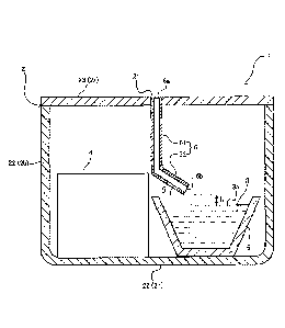
gypsum-based powder products and phosphate-based powder
products are used. These dental powder products are set by
being mixed with a liquid such as water at the time of use (at
the time of producing embedding material, tooth mold,
artificial tooth, and the like) . Dust is generated in handling
a powder product (hereinafter, referred to as "scattering
property of powder" ) , and therefore products that generate only
a small amount of dust (so-called dust-free type) so that a
working environment can be kept comfortable are preferred and
a large number of such products are distributed.
[0003] It is not limited to the dental industry that a
working environment becomes good if the generation amount of
dust is small in handling a powder product. For example, powder
products (hereinafter, also simply referred to as "powders")
are also widely used in various industrial fields such as
construction industry (such as building industry and civil
engineering industry) , various types of manufacturing industry
(such as steel industry, chemical/petroleum products industry,
transportation machinery industry, and food manufacturing
CA 03022676 2018-10-30
2
industry). It is often desired that powders used in various
industrial fields and powders produced in various industrial
fields also have characteristics that dust does not scatter as
much as possible.
[0004] As one example in the above-described dental
industry, Patent Literature 1 discloses invention relating to
a low-dust powder dental gypsum composition composed of a
four-component formulation containing (a) hemihydrate gypsum,
(b) an adjuster, (c) a predetermined humectant, and (d) a
predetermined anionic surfactant.
[0005] On the other hand, as a method for measuring a
scattering property of a powder, a method in which dust is
generated by some sort of method, a powder (dust) is collected
on a filter from air in which the dust is contained, and the
collection amount of the dust is quantified, a method in which
a dust concentration in air is obtained from the information
on the laser diffraction of sample air, or the like has been
conventionally adopted. For example, the aforementioned
Patent Literature 1 describes in the examples thereof a method
for measuring the mass concentration of dust in such a way that:
a predeteLiained mass of a powder is taken in a metal cylindrical
can to be shaken up and down 5 times at 1 up-and-down cycle per
second; and the lid is detached immediately after the shaking
to measure the mass concentration of dust released from the
surface with a digital dust meter at 3minutes after detaching
the lid.
Citation List
Patent Literature
[0006]Patent Literature 1: Japanese Patent Laid-Open No.
62-212255
Summary of Invention
Technical Problem
[0007] The present inventors have noticed that in
conventional methods for measuring a scattering property of a
CA 03022676 2018-10-30
3
powder, the difference in the measurement result is small
between a powder product on which a treatment for suppressing
the occurrence of dust has been applied (so-called dust-free
product) and a powder product on which such a treatment has not
been applied. A difference in the measurement result is still
less hardly seen between dust-free powders, so that it has been
difficult to evaluate the difference in performance through
comparison between dust-free products. Therefore, even if a
dust-free powder from which the generation amount of dust can
be made smaller than the conventional dust-free powders is
developed, there is a possibility that the excellent
performance cannot be evaluated accurately, and the strong
points and values of the product cannot be shown properly. Such
a circumstance, if brought about, can be a hindrance to the sales
of excellent products.
[0008] Thus, the present invention intends to provide a
method by which a scattering property of a powder can be more
clearly evaluated.
Solution to Problem
[0009] Conventionally, it has been considered that a large
amount of dust is generated by shaking a powder as described
in the aforementioned Patent Literature 1. However, the
present inventors have conducted various studies to obtain a
finding that a larger amount of dust is in fact generated at
the moment of contact between a powder and a liquid when the
powder is dropped onto the liquid, and thus the present
invention has been completed.
[0010] That is, the present invention provides a method
for evaluating a scattering property of a powder, the method
including dropping a powder to be evaluated onto a liquid placed
in a box, thereby scattering the powder as dust, and measuring
a dust concentration in air in the box with a dust meter.
Advantageous Effects of Invention
[0011] The present invention can provide a method by which
CA 03022676 2018-10-30
4
a scattering property of a powder can be more clearly evaluated.
Brief Description of Drawings
[0012] [Figure 1] Figure 1 is a diagram illustrating an outline
configuration of an apparatus for evaluating a scattering
property of a powder according to one embodiment of the present
invention.
[Figure 2] Figure 2 is a schematic diagram of a section taken
along line A-A in Figure 1.
[Figure 3] Figure 3 is a section view illustrating an outline
configuration of an apparatus for evaluating a scattering
property of a powder according to another embodiment of the
present invention, the section view corresponding to Figure 2.
[Figure 4] Figure 4 is a section view illustrating an outline
configuration of an apparatus for evaluating a scattering
property of a powder according to yet another embodiment of the
present invention, the section view corresponding to Figure 2.
Description of Embodiments
[0013] Hereinafter, embodiments of the present invention
will be described, but the present invention is not limited to
the following embodiments.
[0014] A method for evaluating a scattering property of
a powder according to one embodiment of the present invention
includes dropping a powder to be evaluated onto a liquid placed
in a box, thereby scattering the powder as dust in the box, and
measuring a dust concentration in air in the box with a dust
meter.
[0015] When the powder to be evaluated drops onto the
liquid placed in the box, a larger amount of dust can be generated
in the box than in the case where the powder is dropped onto
a place where the liquid does not exist. In this way, in the
present invention, by actively scattering the powder to be
evaluated as dust and measuring the dust concentration in air
in the box on that occasion with a dust meter, whether the powder
is easy to scatter or hard to scatter is evaluated. In other
CA 03022676 2018-10-30
words, by dropping a powder onto a liquid placed in a box to
scatter the powder actively as dust, the difference in the value
of the concentration of the dust in air in the box becomes clearer
between a powder that is easy to scatter and a powder that is
hard to scatter. Therefore, the evaluation of the difference
in performance between dust-free powders through comparison can
also be conducted, so that the scattering property of a powder
can be more clearly evaluated. That is, with respect to the
evaluation of a scattering property for a powder or powders,
the present method is more suitable for relatively evaluating
the scattering property for a plurality of powders through
comparison.
[0016] Hereinafter, the method for evaluating a
scattering property of a powder according to one embodiment of
the present invention will be described in detail with reference
to the accompanying drawings usable for the method, each
illustrating an outline configuration of an apparatus for
evaluating a scattering property of a powder according to one
embodiment of the present invention. Incidentally, the same
reference sign is given to the components which are common in
respective figures, and the description may be omitted.
[0017] Figure 1 is a plan view viewed from above, the plan
view schematically illustrating an outline configuration of
arrangement relation in an apparatus 1 for evaluating a
scattering property of a powder according to one embodiment of
the present invention. Figure 2 is a section view taken along
line A-A in Figure 1 and is a schematic diagram illustrating
a state where a liquid 3 is arranged in a box 2. The apparatus
1 for evaluating a scattering property illustrated in Figure
1 and Figure 2 is provided with: the box 2 in which the liquid
3 is placed; and a dust meter 4 that measures the dust
concentration in air in the box 2 when a powder to be evaluated
drops onto the liquid 3 placed in the box to scatter as dust.
[0018] The box 2 can form a space (space to be an object
of measurement) where the powder to be evaluated scatters as
dust. The shape of the box 2 is not particularly limited and
CA 03022676 2018-10-30
6
can be a shape having an upper portion 2a, a side portion 2b,
and a bottom portion 2c, and when the shape is expressed in terms
of a planar view shape viewed from the upper portion 2a or from
the bottom portion 2c, examples thereof include an
approximately triangular shape, an approximately square shape,
an approximately polygonal shape, an approximately circular
shape, and an approximately elliptical shape. For example, the
box 2 in an approximately rectangular parallelepiped shape
having the upper portion 2a, the side portion 2b, and the bottom
portion 2c can be suitably used. It is preferable that the
volume of the box 2, namely the volume of the space into which
a powder is scattered, be about 10 to about 300 L, more preferably
about 10 to about 150 L.
[0019] It is preferable that the box 2 be provided with
a hole portion 21, to be an inlet of a powder into the box 2,
at a position above the level 3a of the liquid 3 to be placed
in the box 2 in order to drop the powder onto the liquid 3 placed
in the box 2. More preferably, as illustrated in Figure 1 and
Figure 2, the hole portion 21 is provided at the upper portion
2a of the box 2 in that the hole portion 21 is positioned above
the level 3a of the liquid 3 to be placed in the box 2, thereby
making it easy to drop the powder from the hole portion 21 onto
the liquid 3 placed in the box 2. The use of a supply path,
which will be described later, allows the powder to drop onto
the liquid 3 placed in the box 2 even if the hole portion is
provided at the side portion 2b of the box 2 as long as the
position is above the level 3a of the liquid 3.
[0020] Although the use of the box 2 whose upper portion
2a is open allows the powder to drop from the opening onto the
liquid 3 placed in the box 2, the box 2 provided with a hole
portion 21 is preferable in that the portions other than the
hole portion 21 can form a closed space (almost tightly closed
space) . Such an almost tightly closed box 2 can make it hard
for dust, which is generated when the powder is dropped onto
the liquid 3 placed in the box 2, to be subjected to an influence
of an air stream outside the box 2. As a result, the measurement
CA 03022676 2018-10-30
accuracy can be enhanced. Accordingly, from the viewpoint of
capable of contributing to the enhancement of the measurement
accuracy, it is preferable that the box 2 be the almost tightly
closed box 2 in which the portions other than the hole portion
21 form a closed space. In addition, from the viewpoint of the
enhancement of the measurement accuracy and from the viewpoint
that the powder, which has dropped onto the liquid 3, can scatter
sufficiently as dust, it is preferable that the diameter of the
hole portion 21 be about 10 to about 100 mm.
[0021] As illustrated in Figure 2, it is preferable that
the box 2 be provided with: a box main body 22 whose upper portion
is open; and a lid 23 that covers the upper portion of the box
main body 22 and that the above-described hole portion 21 be
provided at the lid 23. In this case, the box main body 22
constitutes the side portion 2b and the bottom portion 2c of
the box 2, and the lid 23 constitutes the upper portion 2a of
the box 2. The use of the box 2 provided with: a box main body
22; and a lid 23 having a hole portion 21 makes it easy to arrange
the liquid 3 and the dust meter 4 in the box 2 and makes the
measurement operation easy by detaching the lid 23 from the box
main body 22 at a measurement preparation stage before the
measurement. In addition, when the measurement is performed,
putting the lid 23 on the upper portion of the box main body
22 allows the above-described almost tightly closed box to be
formed, thereby capable of contributing to the enhancement of
the measurement accuracy.
[0022] Although not illustrated in the figures, a slide
type or push-pull type opening/closing portion may be provided
at the upper portion 2a and/or the side portion 2b of the box
2 in place of the lid 23 or together with the lid 23. By making
the opening/closing portion open, the liquid 3 and the dust
meter 4 can be arranged in the box 2 at a measurement preparation
stage, and the liquid 3 and the dust meter 4 can be taken out
of the box 2 when the measurement is completed or when the
measurement is not performed. In addition, when the
measurement is performed, making the opening/closing portion
CA 03022676 2018-10-30
8
close allows the above-described almost tightly closed box to
be formed, thereby capable of contributing to the enhancement
of the measurement accuracy.
[0023] It is preferable that the box 2 be transparent or
semitransparent to such an extent that the inside of the box
2 is visually recognizable from the outside of the box 2. In
this case, the whole or part of the box 2 may be transparent
or semitransparent as long as the inside of the box 2 is visually
recognizable from the outside of the box 2. Examples of the
material for the box 2 whose inside is visually recognizable
from outside include plastics and glass, and from the viewpoint
of production costs, mass, handling properties, safety, etc.,
plastics are preferable. Examples of the plastics include
polypropylene, polyethylene, acrylic resins, and polyester
resins. In the case where the box is provided with the
above-described box main body 22 and lid 23, or the
above-described box main body 22 and opening/closing portion,
the box main body 22 and the lid 23, or the box main body 22
and the opening/closing portion may be formed with the same type
of material or may be formed with different types of materials.
[0024] The powder to be evaluated is not particularly
limited. Any powder having a possibility of scattering as dust
when used for applications according to the powder can be the
object of evaluation. Examples of the material for the powder
include cereal flour such as wheat flour, rice flour, corn flour,
and dogtooth violet starch, inorganic powders such as calcium
sulfate, calcium carbonate, calcium hydroxide, silicon dioxide,
talc, iron oxide, aluminum, aluminum oxide, aluminum hydroxide,
magnesium oxide, and magnesium hydroxide, and synthetic resin
powders. In addition, for example, powder products obtained
by mixing different types or the same types of a plurality of
powders, such as gypsum, mortar, cement, and dental powder
products, can also be used as the powder to be evaluated.
[0025] The method and the apparatus 1 according to the
present embodiment are suitable for relatively evaluating the
scattering property of a powder, as described previously, and
CA 03022676 2018-10-30
9
therefore as a powder to be evaluated, a product on which a
treatment of suppressing the occurrence of dust is applied,
namely a powder product which is sold as a so-called dust-free
product, is more suitable. Examples of more suitable powder
products include dental powder products such as dental
gypsum-based embedding materials, dental phosphate-based
embedding materials, dental silica-based embedding materials,
dental hard gypsum, dental superhard gypsum, and dental
calcined gypsum.
[0026] It is preferable that the amount of a powder to be
dropped onto the liquid 3 be 0.05 to 0.80 g, more preferably
0.08 to 0.65 g per 1 L of the volume of the box 2 so that an
appropriate amount of the powder can scatter as dust in the box
2. The amount of the powder to be dropped onto the liquid 3
can be appropriately adjusted according to the characteristics
of the powder to be evaluated, such as density.
[0027] The liquid 3 to be placed in the box 2 may be prepared
in the box 2 at the time of measurement at the latest. When
the powder drops onto the liquid 3 in measuring the dust
concentration, the powder is mixed into the liquid 3, and
therefore it is desirable that the liquid 3 be replaced every
time the dust concentration of the powder is measured.
Therefore, the liquid 3 may be placed in the box 2 preferably
at the time of measurement, more preferably at every measurement.
Still more preferably, as illustrated in Figure 2, the liquid
may be placed in the box 2 in such a way that the liquid is put
in a container 5, the upper portion of which is open, at the
time of measurement, and the container 5 with the liquid 3 being
put therein is accommodated in the box 2. The use of such a
container 5 makes it easy to replace the liquid 3 and to wash
the part for putting the liquid 3 therein.
[0028] In the case where the above-described container 5
is used, the apparatus 1 for evaluating a scattering property
can be further provided with a container 5 the upper portion
of which is open and in which the liquid 3 is to be put
(hereinafter, sometimes referred to as "container for liquid") .
CA 03022676 2018-10-30
In this case, it is desirable that the container 5 for liquid
be detached at every measurement, and therefore it is preferable
that in the box 2, a mark be provided at a position where the
container 5 for liquid is arranged, and it is also preferable
that a fixing portion for fixing the container 5 for liquid at
a predetermined position in the box 2 be provided. As the
position where the liquid 3 (container 5 for liquid) is arranged
in the box 2, an edge in the box 2 is preferable. For example,
in the case where the box 2 has a shape containing corners
(including round corners) in the planar view of the bottom
portion 2c, such as the box 2 of an almost rectangular
parallelepiped, as illustrated in Figure 1, it is preferable
that the liquid 3 (container 5 for liquid) be placed at a corner
in the bottom portion 2c in the box 2. Separating the dust meter
4 at a certain distance from the liquid 3 that is a source of
generating dust by arranging the liquid 3 at a position of an
edge or a corner in the box 2 and arranging the dust meter 4,
which will be described later, so as to oppose to the position
of the liquid 3, or by other methods, can contribute to the
enhancement of the measurement accuracy.
[0029] The container 5 for liquid is not particularly
limited as long as it has a shape whose upper portion is open
in such an extent that the powder to be evaluated drops onto
the level 3a of the liquid 3 which is put in the container 5
to enable sufficient contact. Examples of such a container 5
include a dish type, a bowl type, and a cup type. It is
preferable that the liquid 3 be put in the container 5 in such
an amount that the liquid 3 has a certain extent of depth so
that the powder which has dropped onto the liquid 3 can scatter
sufficiently as dust, and therefore it is preferable that the
container 5 be of a bowl type or of a cup type. The amount of
the liquid 3 to be placed in the box 2 is not particularly limited
and can be appropriately determined according to the volume of
the box 2 and the use amount of the powder, and it is preferable
that the amount of the liquid to be placed in the box 2 be set
to 50 to 2400 mL, more preferably 80 to 1000 mL.
CA 03022676 2018-10-30
ii
[0030] Incidentally, as described above, from the
viewpoint of easiness of replacement of the liquid 3, and other
viewpoints, it is preferable that the liquid 3 be put in the
container 5 for liquid, which is other than the box 2, but the
liquid 3 may be put directly in the box 2. For example, the
liquid 3 may be placed in the box 2 by being put in a liquid
injection portion formed in a dish shape, a bowl shape, a cup
shape, and the like, the liquid injection portion provided in
the box 2, or by being put in a liquid injection portion formed
with a partition plate or the like.
[0031] The size of the opening of the container 5 for liquid
or the liquid injection portion (size of level 3a) is not
particularly limited as long as the size is in such an extent
that the powder to be evaluated drops onto the level 3a of the
liquid 3 to enable sufficient contact, and the powder, when
drops onto the liquid 3, can sufficiently scatter as dust. It
is preferable that the size of the opening of the container 5
for liquid or the liquid injection portion (size of level 3a)
be larger than the diameter of the previously described hole
portion 21 of the box 2 and the width or the diameter of the
supply path, which will be described later, that introduces the
powder from the hole portion 21 to the liquid 3.
[0032] It is preferable to use the type of liquid 3
according to the actual usage conditions of the powder to be
evaluated. For example, in the case where the powder to be
evaluated is a dental gypsum-based embedding material or
calcined gypsum (such as dental hard gypsum, dental superhard
gypsum and dental calcined gypsum) for dental models, the dental
gypsum-based embedding material or the calcined gypsum for
dental models is used by being mixed with water, and therefore
it is preferable to use water as the liquid 3. In addition,
for example, in the case where the powder to be evaluated is
a phosphate-based dental embedding material, the dental
embedding material is used by being mixed with an aqueous
solution of colloidal silica, and therefore it is preferable
to use an aqueous solution of colloidal silica as the liquid
CA 03022676 2018-10-30
12
3. Further, in the case where the application of the powder
to be evaluated is not specified, in the case where a powder
has diverse applications, in the case where the powder is not
used by being kneaded with a liquid, or other cases, it is
preferable to use water as the liquid 3.
[0033] To drop the powder onto the liquid 3 placed in the
box 2, it is preferable to use a supply path 6 that introduces
the powder from the hole portion 21 provided at the box 2 to
the liquid 3 placed in the box 2. In the case where this supply
path 6 is used, the apparatus 1 for evaluating a scattering
property can be further provided with a supply path 6 that
introduces the powder from the hole portion 21 to the liquid
3. Specifically, the supply path 6 can be provided so as to
be connected to the aforementioned hole portion 21 provided at
the box 2. In this case, the side of the hole portion 21 in
the supply path 6 can be used as a portion where the powder is
introduced (introduction portion) 6a, and the edge on the
opposite side of the introduction portion 6a can be used as a
portion where the powder is supplied to the liquid 3 (supply
portion) 6b. In Figure 2, the configuration in which the hole
portion 21 and the supply path 6 are connected in such a way
that the side of the introduction portion 6a in the supply path
6 is inserted and accommodated in the hole portion 21 of the
box 2 is given as an example, but the supply path 6 may be provided
so that the side of the introduction portion 6a penetrates from
the hole portion 21 to the outside of the box 2.
[0034] The supply path 6 is provided so that the powder,
when drops onto the liquid 3 placed in the box 2, can be scattered
as dust. Examples of the shape of the supply path 6 include
a tubular shape, a semi-tubular shape, and a slope shape, and
examples of the shape of the section of the supply path 6 include
a circular shape, elliptical shape, a square shape, a
rectangular shape, an arch shape, and a U-shape
[0035] It is preferable that the supply path 6 have a
tubular shape (supply pipe) so that the powder, when drops onto
the liquid 3, can scatter as dust without scattering as dust
CA 03022676 2018-10-30
13
in the space in the box 2 at a stage in which the powder passes
through the supply path 6 before the powder drops onto the liquid
3. The width (diameter) of the supply path 6 (supply pipe) and
the width (diameter) of the above-described introduction
portion 6a and supply portion 6b can be set so as to be about
the same size as the diameter of the previously described hole
portion 21 provided at the box 2.
[0036] The supply path 6 may be provided in a linear shape
from the hole portion 21 of the box 2 toward the liquid 3, may
be provided in a curved shape, or may be provided in a linear
shape from the hole portion 21 toward the liquid 3 along the
direction of the height of the box 2. Further, the supply path
6 may be provided with: a portion (perpendicular portion) 61
along the direction of the height of the box 2 (vertical
direction relative to level 3a of liquid 3) ; and a portion
(inclination portion) 62 inclined relative to the direction of
the height of the box 2 or relative to the level 3a of the liquid
3. In this case, in the supply path 6, the side of the
introduction portion 6a may be the inclination portion or the
perpendicular portion, and the side of the supply portion 6b
may also be the inclination portion or the perpendicular
portion.
[0037] More preferably, as illustrated in Figure 2, the
supply path 6 is inclined, on a side of a supply portion 6b that
supplies the powder to the liquid 3, relative to the level 3a
of the liquid 3, and comprises an inclination portion 62 that
slides the powder down toward the liquid 3. The powder supplied
from the supply portion 6b that is provided continuously to this
inclination portion 62 drops onto the liquid 3 from an oblique
upper direction relative to the level 3a of the liquid 3. By
allowing the supply path 6 to be provided with the inclination
portion 62, the powder, when drops onto the liquid 3 from the
inclination portion 62, can be actively scattered as dust. It
is preferable that the inclination portion 62 have a
configuration such that at least the side of the supply portion
6b is inclined relative to the level 3a of the liquid 3, and
CA 03022676 2018-10-30
14
the whole of the supply path 6 may be inclined relative to the
level 3a of the liquid 3.
[0038] It is preferable that the angle B made by the
inclination portion 62 and the level 3a of the liquid 3 be 20
to 70 , more preferably 30 to 60 . Due to the inclination
portion 62 in such a range of angles, it becomes easier for the
powder that has dropped onto the liquid 3 from the supply portion
6b at the tip of the inclination portion 62 to scatter as dust.
[0039] Incidentally, in Figure 2, a tubular supply path
(supply pipe) 6 is illustrated as an example. In the supply
pipe 6, the side of the connection with the hole portion 21 of
the box 2 is used as an introduction port (introduction portion)
6a to which a powder is introduced, and the opposite side of
the introduction port 6a is used as a supply port (supply
portion) 6b from which the powder is supplied to the liquid 3.
The supply pipe 6 is provided with: the perpendicular portion
61 in which the side of the introduction port 6a is formed along
the direction of the height of the box 2; and the inclination
portion 62 formed continuously from the perpendicular portion
61 to the supply port 6b.
[0040] It is preferable that in the supply path 6, the
supply portion 6b be provided at a predeteimined height apart
from the level 3a of the liquid 3 so that the powder that has
dropped onto the liquid 3 can more easily scatter as dust. In
the apparatus illustrated in Figure 2, in the supply path 6,
the supply port (supply portion) 6b is provided at a
predetermined height h apart from the level 3a of the liquid
3. It is preferable that the distance (height) h between the
level 3a of the liquid 3 and the lower end of the supply port
(supply portion) 6b be 1 to 30 mm, more preferably 5 to 15 mm.
[0041] As illustrated in Figure 3, it is preferable to use
a hopper section 7 that is connected on the hole portion 21 of
the box 2 so that the powder can be easily introduced in the
box 2 and that the powder can be easily put in the introduction
portion 6a in the supply path 6. In this case, an apparatus
for evaluating a scattering property can be provided with
CA 03022676 2018-10-30
115
a hopper section 7 on the box 2, the hopper section 7 to be
connected to the hole portion 21 of the box 2. Figure 3 is an
outline configuration diagram illustrating an example in which
the hopper section 7 is attached to the hole portion 21 of the
box 2 in the apparatus illustrated in Figure 2. In the apparatus
illustrated in Figure 3, an end portion 7a on the outlet side
of the hopper section 7 is inserted in the introduction port
6a in the supply path 6 in which the side of the introduction
port 6a is inserted and accommodated in the hole portion 21 of
the box 2, but the connection mode of the hopper section 7, the
hole portion 21, and the supply path 6 (introduction port 6a)
is not limited. For example, the introduction port 6a in the
supply path 6 may be provided so as to penetrate from the hole
portion 21 to the outside of the box 2, and the end portion 7a
on the outlet side of the hopper section 7 may be connected to
the introduction port 6a at a position outside the box 2, the
position apart upward from the hole portion 21 of the box 2.
In addition, for example, the end portion 7a on the outlet side
of the hopper section 7 may penetrate through the hole portion
21 to be connected to the introduction port 6a in the supply
path 6 at a position inside the box 2, the position apart downward
from the hole portion 21.
[0042] As the dust meter 4, a general-purpose dust
measurement device for use in measuring working environments
can be used. Examples of the dust meter 4 that can be used
include a light scattering type dust measurement device, alight
absorption type dust measurement device, and a volt balance type
dust measurement device. Among these, a light scattering dust
measurement device is preferable from the viewpoint of easy
usability.
[0043] It is preferable that the dust meter 4 be placed
in the box 2 at the time of use (at the time of measurement).
Due to the dust meter 4 arranged in the box 2, the dust
concentration in air in the box 2 when the powder is dropped
onto the liquid 3 placed in the box 2 and is scattered as dust
can be measured with good accuracy. As illustrated in Figure
CA 03022676 2018-10-30
16
1, the dust meter 4 is more preferably arranged at a position
of an edge (corner) in the box 2, and it is preferable to arrange
the dust meter 1 so as to face to the previously described
position of arranging the liquid 3 in that such arrangement
expands the measurement range and can contribute to the
enhancement of the measurement accuracy.
[0044] The dust meter 4 is not necessarily placed in the
box 2 at the time of use (at the time of measurement) and may
be placed outside the box 2 as long as the dust concentration
in air in the box can be measured. For example, as illustrated
in Figure 4, an air inlet pipe 41 for sucking air in the box
2 and an exhaust pipe 42 for exhausting the sucked air out into
the box 2 can be attached to the dust meter 4 in the apparatus
11 for evaluating a scattering property. By using the dust
meter 4 provided with the air inlet pipe 41 and the exhaust pipe
42 each connected to the inside of the box 2, the dust
concentration in air in the box 2 can be measured with the dust
meter 4 even in the case where the dust meter 4 is placed outside
the box 2. In this case, an air inlet hole 241 for feeding air
in the box 2 into the dust meter 4 through the air inlet pipe
41 by being connected to the air inlet pipe 41, or an exhaust
hole 242 for feeding air into the box 2 through the exhaust pipe
42 by being connected to the exhaust pipe 42 can be provided
at the box 2. In the apparatus 11 for evaluating a scattering
property illustrated in Figure 4, the air inlet pipe 41 is
connected to the air inlet port of the dust meter 4 and the air
inlet hole 241 provided at the side portion 2b of the box 2,
and the exhaust pipe 42 is connected to the exhaust port of the
dust meter 4 and the exhaust hole 242 provided at the side portion
2b of the box 2.
[0045] The dust concentration to be measured with the dust
meter 4 can be used for evaluating the scattering property of
a powder. When the value of the dust concentration is high,
the powder can be evaluated as easily scatters, and when the
value of the dust concentration is low, the powder can be
evaluated as hardly scatters. It is preferable to measure at
CA 03022676 2018-10-30
1
least one of the number concentration [number/m3] and the mass
concentration [mg/m3] of dust as the dust concentration. In
addition, it is preferable to measure at least one of the maximum
value and the integrated value of the dust concentration, more
preferably both of them. Each of the maximum value and the
integrated value of the dust concentration can be obtained by
measuring the dust concentration at a predetermined time (for
example, I minute) interval, thereby acquiring a plurality (for
example, 5 points) of measured values.
[0046] It is preferable that the measurement procedure in
the method for evaluating a scattering property of a powder
according to the present embodiment include: a step of arranging
the liquid 3 (more preferably, container 5 with liquid 3 being
put therein) in the box 2; a step of starting the measurement
with the dust meter 4; and a step of dropping the powder to be
evaluated onto the liquid 3. This measurement procedure may
include a step of installing the dust meter 4 in the box 2 or
outside the box 2 before starting the measurement with the dust
meter 4. More preferably, the measurement with the dust meter
4 is started before dropping the powder onto the liquid 3 to
acquire a first measured value as a blank, and thereafter the
powder is dropped onto the liquid 3. In addition, it is
preferable to complete the measurement when the amount of dust
is lowered to about the same extent as the first measured value
(blank) , and it is preferable to measure the dust concentration
at a predetermined time interval (for example, interval of 10
seconds to 120 seconds) from the start of the measurement to
the completion of the measurement.
[0047] Respective types of constitution described above
can be arbitrarily combined. In addition, the method for
evaluating a scattering property of a powder according to one
embodiment of the present invention can also take the following
constitution.
[1] A method for evaluating a scattering property of a powder,
the method comprising dropping a powder to be evaluated onto
a liquid placed in a box, thereby scattering the powder as dust
CA 03022676 2018-10-30
18
in the box, and measuring a dust concentration in air in the
box with a dust meter.
[2] The method for evaluating a scattering property of a powder
according to [1] , wherein the box comprises a hole portion, to
be an inlet of the powder into the box, at a position above a
level of the liquid to be placed in the box.
[3] The method for evaluating a scattering property of a powder
according to [2] , wherein the box comprises: a box main body
whose upper portion is open; and a lid that covers the upper
portion of the box main body, and the lid comprises the hole
portion.
[4] The method for evaluating a scattering property of a powder
according to [2] or [3] , wherein the powder is dropped onto the
liquid using a supply path that introduces the powder from the
hole portion to the liquid.
[5] The method for evaluating a scattering property of a powder
according to [4] , wherein the supply path is inclined, on a side
of a supply portion that supplies the powder to the liquid,
relative to the level of the liquid, and comprises an
inclination portion that slides the powder down toward the
liquid.
[6] The method for evaluating a scattering property of a powder
according to [5] , wherein the supply portion in the supply path
is provided at a predetermined height apart from the level of
the liquid.
[7] The method for evaluating a scattering property of a
powder according to any one of [1] to [6], wherein the liquid
is put in a container whose upper portion is open, the container
with the liquid being put therein is accommodated in the box,
and the liquid is thereby placed in the box.
[8] The method for evaluating a scattering property of a powder
according to any one of [1] to [7] , wherein the powder is a dental
powder product.
[ 0 4 8 ] Further, the apparatus for evaluating a scattering
property of a powder according to one embodiment of the present
invention can also take the following constitution.
= 19
[9] An apparatus for evaluating a scattering property of a
powder, the apparatus comprising: a box in which a liquid is
to be placed; and a dust meter that measures a dust concentration
in air in the box when a powder to be evaluated drops onto a
liquid placed in the box and scatters as dust.
[10] The apparatus for evaluating a scattering property of a
powder according to [9], wherein the box comprises a hole
portion, to be an inlet of the powder into the box, at a position
above a level of the liquid to be placed in the box.
[11] The apparatus for evaluating a scattering property of a
powder according to [10], wherein the box comprises: a box main
body whose upper portion is open; and a lid that covers the upper
portion of the box main body, and the lid comprises the hole
portion.
[12] The apparatus for evaluating a scattering property of a
powder according to [10] or [11], further comprising a supply
path that introduces the powder from the hole portion to the
liquid.
[13] The apparatus for evaluating a scattering property of a
powder according to [12] , wherein the supply path is inclined,
on a side of a supply portion that supplies the powder to the
liquid, relative to the level of the liquid, and comprises an
inclination portion that slides the powder down toward the
liquid.
[14] The apparatus for evaluating a scattering property of a
powder according to [13], wherein the supply portion in the
supply path is provided at a predeteimined height apart from
the level of the liquid.
[15] The apparatus for evaluating a scattering property of a
powder according to any one of [9] to [14], further comprising
a container whose upper portion is open, wherein the container
is to be accommodated in the box, and the liquid is to be put
in the container.
[16] The apparatus for evaluating a scattering property of
a powder according to any one of [9] to [15], wherein the
powder is a dental powder product.
CA 3022676 2020-02-19
CA 03022676 2018-10-30
Examples
[0049] Hereinafter, the present invention will be
described more specifically giving Examples, but the present
invention is not limited to the following Examples.
[0050]<Preparation of Apparatus>
A polypropylene storage case (trade name "ST BOX 25"
manufactured by Astage CO., LTD.) of 360 mm in width, 240 mm
in height, and 240 mm in depth (volume of about 20 L) , the storage
case provided with a box main body and a lid, was used as a box.
In the lid of this box, a hole portion in a circular shape having
a dimeter of 30 mm was provided at a portion on the right-hand
side portion in the width direction and on the approximately
central portion in the depth direction (refer to Figure 1) . On
one corner side in this box, a container whose upper portion
is open was arranged, and a laser light scattering type dust
meter (trade name "Dust Monitor Dust Meter DC170" manufactured
by SATOTECH) was arranged on the corner side diagonal to the
corner where this container was arranged (refer to Figure 1) .
The center-to-center distance between the container and the
dust meter in planar view was about 200 mm. To drop a powder,
a supply pipe that introduces the powder from the hole portion
of the box into the container arranged in the box was used. In
the box, a powder introduction port of the supply pipe (diameter
of pipe: 30 mm, length of perpendicular portion: 60 mm, length
of inclination portion: 95 mm, angle 0: 35 ) was inserted into
the hole portion of the box to connect the hole portion and the
supply pipe (refer to Figure 2 and Figure 3) .
[0051] (Example 1)
In Example 1, a dental gypsum-based embedding material
(trade name "SaKura Quick 20" manufactured by Yoshino Gypsum
Co., Ltd.) was used as a powder to be evaluated. This powder
is used by being mixed with water, and therefore, 150 mL of water
was put in advance in the container arranged in the box. On
that occasion, the distance h between the level of the liquid
in the container and the lower end of the supply port of the
CA 03022676 2018-10-30
21
supply pipe was 5mm. The measurement of the dust concentration
with the dust meter was started before dropping the powder onto
water. The interval of measuring the dust concentration was
set to 1 minute, and at 10 seconds after the first measurement
was completed, 5 g of the powder was dropped onto water in the
container from a hopper section (refer to Figure 3) attached
to the hole portion of the box through the supply pipe, thereby
scattering the powder as dust. Up to 5 measured values of the
dust concentration (number concentration of particles having
particle diameter of 0.5 gm or more) in air in the box on that
occasion were acquired.
[00521 (Example 2)
In Example 2, the dust concentration was measured in the
same manner as in Example 1 except that a powder obtained by
adding a nonionic surfactant, as a treatment for suppressing
the occurrence of dust, to the powder used in Example 1 (dental
gypsum-based embedding material treated so as to be dust-free)
was used in place of the powder used in Example 1.
[0053](Comparative Example 1)
In Comparative Example 1, the dust concentration was
measured in the same manner as in Example 1 except that water
was not put in the container arranged in the box.
[0054](Comparative Example 2)
In Comparative Example 2, the dust concentration was
measured in the same manner as in Example 2 except that water
was not put in the container arranged in the box.
[0055](Example 3)
In Example 3, the dust concentration was measured in the
same manner as in Example 1 except that white cement ("White
Portland Cement" manufactured by TAIHEIYO CEMENT CORPORATION)
was used as a powder to be evaluated in place of the powder used
in Example 1.
[0056](Example 4)
In Example 4, the dust concentration was measured in the
same manner as in Example 3 except that a powder obtained by
adding a nonionic surfactant, as a treatment for suppressing
CA 03022676 2018-10-30
22
the occurrence of dust, to the powder used in Example 3 (white
cement treated so as to be dust-free) was used in place of the
powder used in Example 3.
[0057] (Comparative Example 3)
In Comparative Example 3, the dust concentration was
measured in the same manner as in Example 3 except that water
was not put in the container arranged in the box.
[0058] (Comparative Example 4)
In Comparative Example 4, the dust concentration was
measured in the same manner as in Example 4 except that water
was not put in the container arranged in the box.
[0059] (Example 5)
In Example 5, the dust concentration was measured in the
same manner as in Example 1 except that dental hard gypsum (trade
name "New Hi-Stone Yellow" manufactured by Yoshino Gypsum Co.,
Ltd.) was used as a powder to be evaluated in place of the powder
used in Example 1 and that the amount of the powder dropped was
changed from "5 g" in Example 1 to "10 g".
[0060] (Example 6)
In Example 6, the dust concentration was measured in the
same manner as in Example 5 except that a powder obtained by
adding a nonionic surfactant, as a treatment for suppressing
the occurrence of dust, to the powder used in Example 5 (dental
hard gypsum treated so as to be dust-free) was used in place
of the powder used in Example 5.
[0061] (Comparative Example 5)
In comparative Example 5, the dust concentration was
measured in the same manner as in Example 5 except that water
was not put in the container arranged in the box.
[0062] (Comparative Example 6)
In Comparative Example 6, the dust concentration was
measured in the same manner as in Example 6 except that water
was not put in the container arranged in the box.
[0063] The maximum value
among the five measured values
of the dust concentration measured in each of Examples and
Comparative Examples, and the integrated value of the 5 measured
. ,
CA 03022676 2018-10-30
23
values in total were used for evaluation. The results are shown
in Tables 1 to 3.
24
[0064]
Table 1 Results of experiments using dental gypsum-based embedding material
Comparative Example Comparative Example
Example 1 Example 2
1
2
Treated or not so as
Not treated Treated Not treated
Treated
to be dust-free
Maximumvalueofdust
concentration (x 104 619 76 23
11
number/L)
0
Integrated value of
0
dust concentration 2246 158 44
26
(x 104 number/L)
0
0
0
0
25
[0065]
Table 2 Results of experiments using white cement
Comparative Example Comparative Example
Example 3 Example 4
3
4
Treated or not so as
Not treated Treated Not treated
Treated
to be dust-free
Maximum value of dust
concentration (x 104 315 68 159
40
number/L)
Integrated value of
dust concentration 1020 105 306
80
(x 104 number/L)
1-8
26
[0066]
Table 3 Results of experiments using dental hard gypsum
Comparative Example Comparative Example
Example 5 Example 6
6
Treated or not so as
Not treated Treated Not treated
Treated
to be dust-free
Maximum value of dust
concentration (x 104 209 60 55
29
number/L)
Integrated value of
dust concentration 600 80 118
46
(x 104 number/L)
CA 03022676 2018-10-30
27
[0067] From the comparison of the results of Examples 1
and 2 with the results of Comparative Examples 1 and 2, the
comparison of the results of Examples 3 and 4 with the results
of Comparative Examples 3 and 4, and the comparison of the
results of Examples 5 and 6 with the results of Comparative
Examples 5 and 6, it was found that the difference in the measured
value of the dust concentration due to whether the powder was
treated so as to be dust-free or not was larger in Examples than
in Comparative Examples. Accordingly, it was ascertained that
by dropping a powder onto a liquid placed in a box to scatter
the powder actively as dust, the difference in the dust
concentration in air in the box becomes clearer, so that the
scattering property of a powder can be evaluated more clearly.
Industrial Applicability
[0068] The method for evaluating a scattering property of
a powder or the apparatus for evaluating a scattering property
of a powder according to one embodiment of the present invention
can evaluate the scattering property of a powder more clearly
and therefore are useful in using, producing, selling, etc. a
powder product, particularly in selling, etc. a powder product
from which the generation amount of dust is suppressed.
Reference Signs List
[006911, 10, 11 Apparatus for evaluating a scattering
property of a powder
2 Box
3 Liquid
4 Dust meter
Container
6 Supply path