Note: Descriptions are shown in the official language in which they were submitted.
17TOL957CIP2CA
SEISMIC CLAMP FOR
NON-STRUCTURAL COMPONENTS IN A BUILDING
FIELD OF THE DISCLOSURE
[0001] The present disclosure generally relates to a seismic clamp for non-
structural
components in a building. The seismic clamp can be used, for example, as part
of a seismic
sway brace or a restraint.
BACKGROUND OF THE DISCLOSURE
[0002] Seismic supporting systems may be used to support non-structural
components
(e.g., pipes) in a building. Such seismic supporting systems include seismic
sway braces and
restraints (e.g., branch line restraints). Seismic sway braces are used to
minimize the differential
movement between non-structural components (e.g., pipes) in a building and the
building itself.
Examples of non-structural components in a building are utility pipes, which
may include, but
are not limited to, plastic pipes, conduits, round ducts, other types of
pipes, etc. A properly
installed sway brace makes it possible for the building and the non-structural
pipe to move as a
single unit during an earthquake, thereby limiting damage to the non-
structural pipe. Restraints
hold the non-structural components in place to a lesser degree than seismic
sway braces. For
example, restraints inhibit the movement of fire sprinkler branch lines which
could cause damage
to themselves, the structure or other nearby non-structural systems, such as
air handling ducts,
plumbing or electrical systems. Building code NEPA describes requirements for
both seismic
sway braces and restraints. There are other types of seismic supporting
systems other than
seismic sway braces and restraints.
[0003] Conventional seismic supporting systems may include a seismic clamp
(e.g., pipe
clamp) attached to a bracing pipe or other bracing member. The seismic clamp
is attached to the
non-structural pipe, and the bracing pipe is attached to a structural
component of the building
(e.g., a beam).
SUMMARY OF THE DISCLOSURE
[0004] In one aspect, a braced utility assembly within a building generally
comprises a
utility pipe; a rigid rod; and a seismic clamp securing the utility pipe to
the rigid rod such that the
1
CA 3023198 2018-11-06
I 7TOL957CIP2CA
rigid rod extends transverse to the utility pipe. The seismic clamp includes a
spacer disposed
between the utility pipe and the rigid rod to inhibit the rigid rod from
contacting the utility pipe.
[0005] In another aspect, a method of bracing a utility pipe in a building
generally
comprises securing the utility pipe to a seismic sway brace. The seismic sway
brace includes a
rigid rod and a seismic clamp. The seismic clamp secures the utility pipe to
the rigid rod. The
rigid rod extends transverse to the utility pipe, and the rigid rod and the
utility pipe are free from
contact with one another when the rigid rod and the utility pipe are secured
to the seismic clamp.
[0006] In yet another aspect, a seismic clamp for securing a utility pipe to a
rigid rod
generally comprises a pipe holder configured to secure the utility pipe to the
seismic clamp such
that the utility pipe extends in a first direction. A rod fitting is
configured to secure the rigid rod
to the seismic clamp so that the rigid rod extends in a second direction
transverse to the first
direction. A spacer is disposed between the pipe holder and the rod fitting.
The spacer is
configured to inhibit the rigid rod from contacting the utility pipe when the
utility pipe is secured
to the seismic clamp and the rigid rod is secured to the seismic clamp.
BRIEF DESCRIPTION OF THE DRAWINGS
[0007] FIG. 1 is a perspective of a first embodiment of a seismic clamp for a
seismic
supporting system constructed according to the teachings of the present
disclosure;
[0008] FIG. 2 is a front elevation of the seismic clamp of FIG. 1;
[0009] FIG. 3 is a perspective of a second embodiment of a seismic clamp
constructed
according to the teachings of the present disclosure;
[0010] FIG. 4 is a front elevation of the seismic clamp of FIG. 3;
[0011] FIG. 5 is a perspective of a third embodiment of a seismic clamp
constructed
according to the teachings of the present disclosure;
[0012] FIG. 6 is a front elevation of the seismic sway brace of FIG. 5;
[0013] FIG. 7 is a perspective of a fourth embodiment of a seismic clamp
constructed
according to the teachings of the present disclosure;
[0014] FIG. 8 is a front elevation of the seismic clamp of FIG. 7;
[0015] FIG. 9 is a perspective of a fifth embodiment of a seismic clamp
constructed
according to the teachings of the present disclosure;
[0016] FIG. 10 is a front elevation of the seismic clamp of FIG. 9;
2
CA 3023198 2018-11-06
17TOL957CIP2CA
[0017] FIG. 11 is a perspective of a sixth embodiment of a seismic clamp
constructed
according to the teachings of the present disclosure;
[0018] FIG. 12 is a front elevation of the seismic clamp of FIG. 11;
[0019] FIG. 13 is a perspective of a seventh embodiment of a seismic clamp
constructed according to the teachings of the present disclosure;
[0020] FIG. 14 is a front elevation of the seismic clamp of FIG. 13;
[0021] FIG. 15 is a perspective of a eighth embodiment of a seismic clamp
constructed
according to the teachings of the present disclosure;
[0022] FIG. 16 is a front elevation of the seismic clamp of FIG. 15;
[0023] FIG. 17 is a perspective of a ninth embodiment of a seismic clamp
constructed
according to the teachings of the present disclosure;
[0024] FIG. 18 is a front elevation of the seismic clamp of FIG. 17;
[0025] FIG. 19 is a perspective of a tenth embodiment of a seismic clamp
constructed
according to the teachings of the present disclosure;
[0026] FIG. 20 is a front elevation of the seismic clamp of FIG. 19;
[0027] FIG. 21 is a perspective of a eleventh embodiment of a seismic clamp
constructed according to the teachings of the present disclosure;
[0028] FIG. 22 is a front elevation of the seismic clamp of FIG. 21;
[0029] FIG. 23 is a rear elevation of the seismic clamp of FIG. 21;
[0030] FIG. 24 is a perspective of a twelfth embodiment of a seismic clamp
constructed
according to the teachings of the present disclosure;
[0031] FIG. 25 is a front elevation of the seismic clamp of FIG. 24;
[0032] FIG. 26 is a perspective of a thirteenth embodiment of a seismic clamp
constructed according to the teachings of the present disclosure;
[0033] FIG. 27 is a front elevation of the seismic clamp of FIG. 26;
[0034] FIG. 28 is a perspective of a fourteenth embodiment of a seismic clamp
constructed according to the teachings of the present disclosure;
[0035] FIG. 29 is a front elevation of the seismic brace of FIG. 28;
[0036] FIG. 30 is a perspective of a fifteenth embodiment of a seismic clamp
constructed according to the teachings of the present disclosure;
[0037] FIG. 31 is a front elevation of the seismic brace of FIG. 30;
3
CA 3023198 2018-11-06
17TOL957CIP2CA
[0038] FIG. 32 is a perspective of a sixteenth embodiment of a seismic clamp
constructed according to the teachings of the present disclosure; and
[0039] FIG. 33 is a front elevation of the seismic brace of FIG. 32.
DETAILED DESCRIPTION OF THE DISCLOSURE
[0040] Disclosed herein are embodiments of a seismic clamp for bracing a non-
structural component to a rigid rod within a building. For example, the
seismic clamp may be
suitably configured for use in a sway brace, or a restraint, or other non-
structural seismic
supporting systems. Thus, the described embodiments are not limited to seismic
sway braces or
restraints. In the illustrated embodiments, each seismic clamp is suitably
configured for use with
at least a rigid rod RR having a circular cross-sectional shape, although in
other embodiments the
seismic clamp may be configured for rigid rods having other shapes. Moreover,
the rigid rod
may include a pipe, a solid rod, a threaded rod, a bar, a strut channel, or
other types of rigid rods.
As is generally known, the rigid rod may be secured to and extend from a
structural component
of the building, such as a beam, using a seismic clamp or other device. In the
illustrated
embodiments, each seismic clamp is suitably configured for bracing a non-
structural pipe, such
as a utility pipe, which may include, but is not limited to, a pipe, a
conduit, a round duct, or
another type of pipe, to the rigid rod. For example, in a particular
embodiment, the pipe for use
with the brace may be a plastic pipe, including but not limited to a plastic
pipe comprising
chlorinated polyvinyl chloride (CPVC), or a plastic pipe consisting
essentially of CPVC, or
another type of plastic pipe. In another embodiment, the braced pipe may be a
soft metal or thin
metal pipe. In each illustrated embodiment, the seismic clamp includes a
spacer disposed
between the plastic utility pipe and the rigid rod to inhibit the rigid rod
from contacting the utility
pipe. Also, in each illustrated embodiment, the brace is configured to limit
the force applied to
the utility pipe so that the brace does not deform, either plastically or
elastically, the utility pipe,
and in particular a plastic utility pipe (e.g., a CPVC pipe).
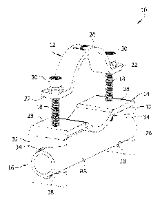
[0041] Referring to FIGS. 1 and 2, a first embodiment of the seismic clamp for
bracing
a non-structural component, such as the utility pipe UP, to the rigid rod RR
within a building is
generally indicated at reference numeral 10. The seismic clamp 10 generally
includes a pipe
holder, generally indicated at 12, configured to secure the utility pipe UP on
the seismic clamp; a
spacer, generally indicated at 14, configured to be disposed between the
utility pipe and the rigid
4
CA 3023198 2018-11-06
17TOL957CIP2CA
rod to inhibit the rigid rod from contacting the utility pipe when the utility
pipe is secure to the
seismic clamp; and a rod fitting, generally indicated at 16, configured to
secure the seismic
clamp to the rigid rod. In this embodiment, the spacer 14 and the rod fitting
16 are integrally
formed as a single, one-piece component, although the components may be formed
separately.
For example, the spacer 14 and the rod fitting 16 may be formed from a piece
of metal, such as a
flat sheet of metal. Moreover, as explained in more detail below, the holder
12 is formed
separate from the spacer 14 and the rod fitting 16 and secured to the
spacer/rod fitting component
by one or more fasteners 18 (e.g., threaded fastener, such as a bolt or
screw).
[0042] Referring still to FIGS. 1 and 2, the pipe holder 12 comprises a strap
including a
generally arcuate central portion 20 defining a bearing surface sized and
shaped to extend
partially around the circumference of the utility pipe UP, and opposite first
and second ears 22
extending outward from opposite ends of the central portion. The strap may be
formed from a
flat piece of metal or other material. The spacer 14 includes a saddle 26
defining bearing surface
on which the utility pipe UP is supported, and opposite first and second ears
28 extending
outward from opposite ends of the saddle. The saddle 26 generally opposes the
central portion
20 of the pipe holder 12, and the first and second ears 28 generally opposes
the respective first
and second ears of the pipe holder 12. The fasteners 18 extend through aligned
openings (e.g.,
threaded openings) extending through the first and second respective ears 22,
28. Tightening the
fasteners 18 brings the holder 12 toward the spacer 14 to secure the utility
pipe UP between the
holder and the spacer. For reasons explained below, in the illustrated
embodiment, the fasteners
18 are torque-limiting bolts, whereby once a desired torque on the bolt head
30 is reached the
bolt head shears off the remainder of the bolt to inhibit additional
tightening of the bolt.
[0043] The illustrated rod fitting 16 includes first and second opposing arms
32
extending from the respective first and second ears 28 of the spacer 14 in a
direction opposite the
holder 12. The arms 32 define rod-receiving openings 34 extending through the
arms 32 and
from front sides of the arms toward rear sides of the arms to allow the rigid
rod RR to enter the
rod-receiving openings through the front sides of the arms. The ends of the
fasteners 18
extending through the ears 28 of the spacer 14 engage the rigid rod RR within
the rod-receiving
openings 34. The arms 32 include bearing surfaces 38 partially defining the
rod-receiving
openings 34 that support the rigid rod RR. The fasteners 18 function as set
screws pressing the
rigid rod RR against the bearing surfaces 38 to secure the fitting 16 to the
rigid rod RR. Through
CA 3023198 2018-11-06
17TOL957C1P2CA
this arrangement, the rigid rod RR and the utility pipe UP extend transverse
(e.g., perpendicular)
with respect to one another.
[0044] In the illustrated embodiment, the brace 10 is configured to limit the
force
applied to the utility pipe UP by the holder 12 so that the holder does not
deform, either
plastically or elastically, the utility pipe, and in particular a plastic
utility pipe (e.g., a CPVC
pipe). In other words, the outer dimension of the utility pipe at the location
where it is being
secured by the holder does not change during or after securement. In the
illustrated embodiment,
the bolt head 30 of each fastener 18 shears off during fastening after a
predetermined torque on
the bolt head has been reached. For example, when the ends of the fasteners 18
engage the rigid
rod RR after a certain amount of tightening, additional torque applied to the
bolt head 30 will
shear the bolt head off the bolt thereby inhibiting additional tightening of
the holder 12 on the
utility pipe UP. In this way, the brace 10 is secured to the rigid rod RR and
the holder does not
deform, either plastically or elastically, the utility pipe UP.
[0045] Referring to FIGS. 4 and 5, a second embodiment of the seismic clamp
for
bracing a non-structural component, such as the utility pipe UP, to the rigid
rod RR within a
building is generally indicated at reference numeral 110. The seismic clamp
110 generally
includes a pipe holder, generally indicated at 112, configured to secure the
utility pipe UP to the
seismic clamp; a spacer, generally indicated at 114, configured to be disposed
between the utility
pipe and the rigid rod to inhibit the rigid rod from contacting the utility
pipe when the utility pipe
is secured to the seismic clamp; and a rod fitting, generally indicated at
116, configured to secure
the seismic clamp to the rigid rod. The pipe holder 112, the spacer 114, and
the rod fitting 116
are integrally formed as a one-piece component, such as from metal (e.g.,
sheet metal). The pipe
holder 112 has a generally U-shape for partially surrounding a circumference
of the utility pipe
UP. The rod fitting 116 includes opposite channel-shaped arms extending
downward from
opposite ends of the pipe holder 112. Each channel-shaped arm includes a first
side wall 117
connected to the corresponding end of the pipe holder, a bottom wall 119
extending inward from
the first side wall, and a second side wall 121 extending upward from the
bottom wall in
opposing relationship with the first side wall. Aligned rod-receiving openings
123 extend
through the first and second side walls 117, 119 and are sized and shaped to
receive the rigid rod
therethrough. The spacer 114 includes tabs 129 defining bearing surfaces on
which the utility
pipe UP is supported. The tabs 129 extend upward from the upper ends of the
respective second
6
CA 3023198 2018-11-06
17TOL957CIP2CA
side walls 121. The tabs 129 flare outward away from one another to define a
generally V-
shaped saddle.
[0046] In the illustrated embodiment, a central portion of the pipe holder 112
is
bendable out-of-plane at an area of weakness (e.g., notches 127) so that the
tabs 129 of the
spacer 114 (and the rod fitting arms) open up to allow the utility pipe UP to
be received between
the spacer and the central portion of the pipe holder. The pipe holder 112 can
then be closed by
bending the central portion of the pipe holder so that the tabs 129 are
brought toward one
another. In the illustrated embodiment, the brace 110 is configured to limit
the force applied to
the utility pipe UP by the holder 112 so that the holder does not deform,
either plastically or
elastically, the utility pipe, and in particular a plastic utility pipe (e.g.,
a CPVC pipe). In other
words, the outer dimension of the utility pipe UP at the location where it is
being secured does
not change during or after securement. In other embodiments, the pipe holder
112 may not be
bendable out of plane, but instead, the pipe holder may be slidably received
on the utility pipe
UP. Threaded fasteners 118 extend through openings 123 (e.g., threaded
openings) in the bottom
wall 119 and engage the rigid rod RR. The side walls 117, 121 include bearing
surfaces partially
defining the rod-receiving openings 123. The fasteners 118 function as set
screws pressing the
rigid rod RR against the bearing surfaces to secure the fitting 116 to the
rigid rod RR. Through
this arrangement, the rigid rod RR and the utility pipe UP extend transverse
(e.g., perpendicular)
with respect to one another. The fasteners 118 may be torque-limiting bolts.
[0047] Referring to FIGS. 5 and 6, a third embodiment of the seismic clamp for
bracing
a non-structural component, such as the utility pipe UP, to the rigid rod RR
within a building is
generally indicated at reference numeral 210. The seismic clamp 210 generally
includes a pipe
holder, generally indicated at 212, configured to secure the utility pipe UP
to the seismic clamp;
a spacer, generally indicated at 214, configured to be disposed between the
utility pipe and the
rigid rod to inhibit the rigid rod from contacting the utility pipe when the
utility pipe is secured to
the seismic clamp; and a rod fitting, generally indicated at 216, configured
to secure the seismic
clamp to the rigid rod. This seismic clamp 210 is similar to the second
seismic clamp 110,
except as hereinafter described. The pipe holder 212 of the seismic clamp 210
does not bend to
open and close the pipe holder, and the pipe holder has a generally arcuate
bearing surface 220
for the utility pipe UP. Moreover, the tabs 229 of the spacer extend inward
toward one another
and downward from the second side wall 221 of the rod fitting 216 to define a
generally V-
7
CA 3023198 2018-11-06
17TOL957CIP2CA
shaped saddle for the utility pipe UP. The rigid rod RR and the utility pipe
UP extend transverse
(e.g., perpendicular) with respect to one another.
[0048] Referring to FIGS. 7 and 8, a fourth embodiment of the seismic clamp
for
bracing a non-structural component, such as the utility pipe UP, to the rigid
rod RR within a
building is generally indicated at reference numeral 310. The seismic clamp
310 generally
includes a pipe holder, generally indicated at 312, configured to secure the
utility pipe UP to the
seismic clamp; a spacer, generally indicated at 314, configured to be disposed
between the utility
pipe and the rigid rod to inhibit the rigid rod from contacting the utility
pipe when the utility pipe
is secured to the seismic clamp; and a rod fitting, generally indicated at
316, configured to secure
the seismic clamp to the rigid rod. This seismic clamp 310 is similar to the
third seismic clamp
210, except as hereinafter described. The tabs 329 of the spacer 314 extend
inward toward one
another from the first side walls 317 of the respective arms of the rod
fitting 316. Moreover, the
second side walls 321 of the arms of the rod fitting 316 are outward of the
corresponding first
side walls 317 rather than inward thereof. The rigid rod RR and the utility
pipe UP extend
transverse (e.g., perpendicular) with respect to one another.
[0049] Referring to FIGS. 9 and 10, a fifth embodiment of the seismic clamp
for
bracing a non-structural component, such as the utility pipe UP, to the rigid
rod RR within a
building is generally indicated at reference numeral 410. The seismic clamp
410 generally
includes a pipe holder, generally indicated at 412, configured to secure the
utility pipe UP to the
seismic clamp; a spacer, generally indicated at 414, configured to be disposed
between the utility
pipe and the rigid rod to inhibit the rigid rod from contacting the utility
pipe when the utility pipe
is secured to the seismic clamp; and a rod fitting, generally indicated at
416, configured to secure
the seismic clamp to the rigid rod. This seismic clamp 410 is similar to the
first seismic clamp
10, except as hereinafter described. The rod fitting 416 is channel-shaped
including opposing
first and second side walls 432 and a bottom wall 433 interconnecting the
first and second side
walls. Ears 435 at upper ends of the first and second side walls 432 are
connected to the
respective ears 422, 428 of the pipe holder 412 and the spacer 414 by
fasteners 419 extending
through aligned openings (e.g., non-threaded openings). Capped nuts 441 are
threaded on the
fasteners 419 to limit the tightening of the holder 412 on the utility pipe UP
to limit the force
applied to the utility pipe by the holder so that the holder does not deform,
either plastically or
elastically, the utility pipe, and in particular a plastic utility pipe (e.g.,
a CPVC pipe). Rod-
8
CA 3023198 2018-11-06
17TOL957CIP2CA
receiving openings 434 in the first and second side walls 432 receive the
rigid rod RR. A
fastener 445 is threaded in a threaded opening in the bottom wall 433 of the
rod fitting 416 and
engages the rigid rod RR to function as a set screw to secure the brace 410 to
the rigid rod. The
rigid rod RR and the utility pipe UP extend transverse (e.g., perpendicular)
with respect to one
another.
[0050] Referring to FIGS. 11 and 12, a sixth embodiment of the seismic clamp
for
bracing a non-structural component, such as the utility pipe UP, to the rigid
rod RR within a
building is generally indicated at reference numeral 510. The seismic clamp
510 generally
includes a pipe holder, generally indicated at 512, configured to secure the
utility pipe UP to the
seismic clamp; a spacer, generally indicated at 514, configured to be disposed
between the utility
pipe and the rigid rod to inhibit the rigid rod from contacting the utility
pipe when the utility pipe
is secured to the seismic clamp; and a rod fitting, generally indicated at
516, configured to secure
the seismic clamp to the rigid rod. This seismic clamp 510 is similar to the
first seismic clamp
10, except as hereinafter described. The pipe holder 512 includes a keyed
fitting 550 (e.g., a T-
shaped fitting) at one of its ends opposite the end with an ear 522 through
which the fasteners
518 is received and engages the rigid rod RR. The keyed fitting 550 is
receivable in a slot 552
defined by one of the ears 528 of the spacer 514 when the keyed fitting is in
a first orientation.
After keyed fitting 550 is inserted in the slot 552, the pipe holder 512 can
be rotated 90 degrees
so that the opposite ear 522 defined by the pipe holder having an opening
therethrough generally
opposes the corresponding ear 528 of the spacer 514. The fastener 518 can then
be tightened
similar to the description set forth above with respect to the first
embodiment so that the holder
512 does not deform, either plastically or elastically, the utility pipe, and
in particular a plastic
utility pipe (e.g., a CPVC pipe). The rigid rod RR and the utility pipe UP
extend transverse (e.g.,
perpendicular) with respect to one another.
[0051] Referring to FIGS. 13 and 14, a seventh embodiment of the seismic clamp
for
bracing a non-structural component, such as the utility pipe UP, to the rigid
rod RR within a
building is generally indicated at reference numeral 610. The seismic clamp
610 generally
includes a pipe holder, generally indicated at 612, configured to secure the
utility pipe UP to the
seismic clamp; a spacer, generally indicated at 614, configured to be disposed
between the utility
pipe and the rigid rod to inhibit the rigid rod from contacting the utility
pipe when the utility pipe
is secured to the seismic clamp; and a rod fitting, generally indicated at
616, configured to secure
9
CA 3023198 2018-11-06
17TOL957CIP2CA
the seismic clamp to the rigid rod. This seismic clamp 610 is similar to the
fifth seismic clamp
410, except as hereinafter described. The rod openings 634 defined by the
opposing first and
second side walls 632 of the rod fitting 616 are configured to selectively
receive therein a rigid
rod having a circular cross section, as shown in the previous embodiments, or
a rigid rod in the
form of a strut channel SC, as illustrated in FIGS. 13 and 14, to be secured
to the brace 610. The
side walls 632 each includes a retainer having two prongs 658 extending into
the corresponding
opening 634. The retainer prongs 658 are received in the open interior of the
strut channel and
engage the inturned lips defining the open slot of the strut channel when the
strut channel is
received in the opening 634 to capture the strut channel in the opening. The
retainer prongs
define a V-shaped space suitable for receiving and bearing a rigid rod having
a circular cross
section.
[0052] Referring to FIGS. 15 and 16, an eighth embodiment of the seismic clamp
for
bracing a non-structural component, such as the utility pipe UP, to the rigid
rod RR within a
building is generally indicated at reference numeral 710. The seismic clamp
710 generally
includes a pipe holder, generally indicated at 712, configured to secure the
utility pipe UP to the
seismic clamp; a spacer, generally indicated at 714, configured to be disposed
between the utility
pipe and the rigid rod to inhibit the rigid rod from contacting the utility
pipe when the utility pipe
is secured to the seismic clamp; and a rod fitting, generally indicated at
716, configured to secure
the seismic clamp to the rigid rod.
[0053] Referring still to FIGS. 15 and 16, the pipe holder 712 comprises a
strap
including a generally arcuate central portion 720 defining a bearing surface
sized and shaped to
extend partially around the circumference of the utility pipe UP, and opposite
first and second
ears 722 extending outward from opposite ends of the central portion. The
strap may be formed
from a flat piece of metal or other material. The spacer 714 includes a saddle
726 defining
bearing surface on which the utility pipe UP is supported, and opposite first
and second ears 728
extending outward from opposite ends of the saddle. The saddle 726 generally
opposes the
central portion 720 of the pipe holder 712. The first and second ears 728 of
the spacer 714 are
received in openings 729 (e.g., slot shaped openings) in the pipe holder 712
generally adjacent
the ears 722 of the pipe holder to secure the utility pipe UP between the
holder and the spacer.
The pipe holder 712 is secured to the rod fitting 716 by fasteners 730 (e.g.,
bolts) extending
through the first and second ears 722 and threaded into the rod fitting.
CA 3023198 2018-11-06
17TOL957CIP2CA
[0054] The illustrated rod fitting 716 includes opposing first and second
opposing arms
732. In the illustrated embodiment, the first and second opposing arms 732 are
generally in the
form of blocks defining rod-receiving openings 734 extending through the arms
732 such that the
rigid rod RR extends generally transverse (e.g., perpendicular) to the utility
pipe UP. Fasteners
735(e.g., bolts) extend through the opposing arms 732 of the rod fitting 716
engage the rigid rod
RR within the rod-receiving openings 734. The arms 732 include bearing
surfaces partially
defining the rod-receiving openings 734 that support the rigid rod RR. The
fasteners 735
function as set screws pressing the rigid rod RR against the bearing surfaces
to secure the fitting
716 to the rigid rod RR. Through this arrangement, the rigid rod RR and the
utility pipe UP
extend transverse (e.g., perpendicular) with respect to one another.
[0055] In the illustrated embodiment, the brace 710 is configured to limit the
force
applied to the utility pipe UP by the holder 712 so that the holder does not
deform, either
plastically or elastically, the utility pipe, and in particular a plastic
utility pipe (e.g., a CPVC
pipe). In other words, the outer dimension of the utility pipe at the location
where it is being
secured by the holder does not change during or after securement. In the
illustrated embodiment,
the pipe holder 720 and the spacer 714 are sized and shaped to a particular
utility pipe having a
selected size and shape so that the holder does not deform, either plastically
or elastically, the
utility pipe.
100561 Referring to FIGS. 17 and 18, a ninth embodiment of the seismic clamp
for
bracing a non-structural component, such as the utility pipe UP, to the rigid
rod RR within a
building is generally indicated at reference numeral 810. The seismic clamp
810 generally
includes a pipe holder, generally indicated at 812, configured to secure the
utility pipe UP to the
seismic clamp; a spacer, generally indicated at 814, configured to be disposed
between the utility
pipe and the rigid rod to inhibit the rigid rod from contacting the utility
pipe when the utility pipe
is secured to the seismic clamp; and a rod fitting, generally indicated at
816, configured to secure
the seismic clamp to the rigid rod. This seismic clamp 810 is similar to the
eighth seismic clamp
710, except as hereinafter described. The spacer 814 includes first and second
tabs 829
extending inward from adjacent the respective first and second ears 822 of the
pipe holder 812.
The tabs 829 define the bearing surface for supporting the utility pipe UP in
spaced relationship
with the rigid rod RR.
11
CA 3023198 2018-11-06
17TOL957CIP2CA
[0057] Referring to FIGS. 19 and 20, a tenth embodiment of the seismic clamp
for
bracing a non-structural component, such as the utility pipe UP, to the rigid
rod RR within a
building is generally indicated at reference numeral 910. The seismic clamp
910 generally
includes a pipe holder, generally indicated at 912, configured to secure the
utility pipe UP to the
seismic clamp; a spacer, generally indicated at 914, configured to be disposed
between the utility
pipe and the rigid rod to inhibit the rigid rod from contacting the utility
pipe when the utility pipe
is secured to the seismic clamp; and a rod fitting, generally indicated at
916, configured to secure
the seismic clamp to the rigid rod. This seismic clamp 910 is similar to the
eighth seismic clamp
710, except as hereinafter described. The rod fitting 916 is formed as a
single, elongate block
having an upper surface opposing the pipe holder 912 and defining the spacer
914, in particular,
the bearing surface of the spacer. Thus, the spacer 914 and the rod fitting
916 are integrally
formed as a one-piece component.
[0058] Referring to FIGS. 21-23, an eleventh embodiment of the seismic clamp
for
bracing a non-structural component, such as the utility pipe UP, to the rigid
rod RR within a
building is generally indicated at reference numeral 1010. The seismic clamp
1010 generally
includes a pipe holder, generally indicated at 1012, configured to secure the
utility pipe UP to the
seismic clamp; a spacer, generally indicated at 1014, configured to be
disposed between the
utility pipe and the rigid rod to inhibit the rigid rod from contacting the
utility pipe when the
utility pipe is secured to the seismic clamp; and a rod fitting, generally
indicated at 1016,
configured to secure the seismic clamp to the rigid rod.
[0059] Referring still to FIGS. 21-23, the pipe holder 1012 comprises a strap
including
a generally arcuate central portion 1020 defining a bearing surface sized and
shaped to extend
partially around the circumference of the utility pipe UP. The strap may be
formed from a flat
piece of metal or other material. The spacer 1014 includes a sleeve 1026
defining bearing
surface on which the utility pipe UP is supported. The sleeve 1026 is secured
to the rigid rod RR
by a fastener 1027 functioning as a set screw. The sleeve 1026 generally
opposes the central
portion 1020 of the pipe holder 1012.
[0060] The illustrated rod fitting 1016 includes opposing first and second
arms 1032
extending from opposite ends of the pipe holder 1012 and integrally formed
therewith. The first
and second arms rod-receiving openings 1034 extend through the arms 1032 such
that the rigid
rod RR extends generally transverse (e.g., perpendicular) to the utility pipe
UP. Fasteners 1035
12
CA 3023198 2018-11-06
17TOL957CIP2CA
(e.g., bolts) extend through first and second ears 1033 of the rod fitting
1016 engage the rigid rod
RR within the rod-receiving openings 1034. The arms 1032 include bearing
surfaces partially
defining the rod-receiving openings 1034 that support the rigid rod RR. The
fasteners 1035
function as set screws pressing the rigid rod RR against the bearing surfaces
to secure the fitting
1016 to the rigid rod RR. Through this arrangement, the rigid rod RR and the
utility pipe UP
extend transverse (e.g., perpendicular) with respect to one another.
[0061] In the illustrated embodiment, the brace 1010 is configured to limit
the force
applied to the utility pipe UP by the holder 1012 so that the holder does not
deform, either
plastically or elastically, the utility pipe, and in particular a plastic
utility pipe (e.g., a CPVC
pipe). In other words, the outer dimension of the utility pipe UP at the
location where it is being
secured by the holder 1012 does not change during or after securement. In the
illustrated
embodiment, the pipe holder 1020 and the spacer 1014 are sized and shaped to a
particular utility
pipe having a selected size and shape so that the holder does not deform,
either plastically or
elastically, the utility pipe.
[0062] Referring to FIGS. 24 and 25, a twelfth embodiment of the seismic clamp
for
bracing a non-structural component, such as the utility pipe UP, to the rigid
rod RR within a
building is generally indicated at reference numeral 1110. The seismic clamp
1110 generally
includes a pipe holder, generally indicated at 1112, configured to secure the
utility pipe UP to the
seismic clamp; a spacer, generally indicated at 1114, configured to be
disposed between the
utility pipe UP and the rigid rod RR to inhibit the rigid rod RR from
contacting the utility pipe
UP when the utility pipe UP is secured to the seismic clamp; and a rod
fitting, generally
indicated at 1116, configured to secure the seismic clamp to the rigid rod RR.
[0063] Referring still to FIGS. 24 and 25, the pipe holder 1112 comprises an
outer
upper member 1113 and a strap 1115 having an arcuate shape and defining a
bearing surface
sized and shaped to extend partially around the circumference of the utility
pipe UP. The strap
1115 is inward of the upper member 1113. A fastener 1118 is threadably
received in the upper
member 1113 and connected to the strap 1115 so that tightening of the fastener
1118 moves the
strap 1115 relative to the upper member and toward the spacer 1114. The spacer
1114 includes a
sleeve 1126 defining bearing surface on which the utility pipe UP is
supported. The sleeve 1126
is received on the rigid pipe RR and at least partially surrounds the
circumference of the rigid rod
RR. The sleeve 1026 generally opposes the central portion 1120 of the pipe
holder 1112.
13
CA 3023198 2018-11-06
17T0L957CIP2CA
[0064] The illustrated rod fitting 1116 includes opposing first and second
arms 1132
extending from opposite ends of the upper member 1113 of the pipe holder 1112
and integrally
formed therewith. First and second arms rod-receiving openings 1134 extend
through the arms
1132 such that the rigid rod RR extends generally transverse (e.g.,
perpendicular) to the utility
pipe UP. Through this arrangement, the rigid rod RR and the utility pipe UP
extend transverse
(e.g., perpendicular) with respect to one another.
[0065] In the illustrated embodiment, the brace 1110 is configured to limit
the force
applied to the utility pipe UP by the holder 1112 so that the holder does not
deform, either
plastically or elastically, the utility pipe, and in particular a plastic
utility pipe (e.g., a CPVC
pipe). In other words, the outer dimension of the utility pipe UP at the
location where it is being
secured by the holder 1112 does not change during or after securement. In the
illustrated
embodiment, a stop in the form of a sleeve 1150 is received on the bolt 1118
between the bolt
head and the upper member 1113 to restrict movement of the strap 1115 toward
the spacer 1114,
to thereby restrict the force applied to the utility pipe UP positioned
between the strap and the
spacer.
[0066] Referring to FIGS. 26 and 27, a thirteenth embodiment of the seismic
clamp for
bracing a non-structural component, such as the utility pipe UP, to the rigid
rod RR within a
building is generally indicated at reference numeral 1210. The seismic clamp
1210 generally
includes a pipe holder, generally indicated at 1212, configured to secure the
utility pipe UP to the
seismic clamp; a spacer, generally indicated at 1214, configured to be
disposed between the
utility pipe and the rigid rod to inhibit the rigid rod from contacting the
utility pipe when the
utility pipe is secured to the seismic clamp; and a rod fitting, generally
indicated at 1216,
configured to secure the seismic clamp to the rigid rod. This seismic clamp
1210 is similar to the
eighth seismic clamp 710, except as hereinafter described. The spacer 1214
comprises a plate
that is secured between the first and second ears 1222 of the pipe holder 1212
and the first and
second opposing arms 1232 by the fasteners 1230.
[0067] Referring to FIGS. 28 and 29, a fourteenth embodiment of the seismic
clamp for
bracing a non-structural component, such as the utility pipe UP, to the rigid
rod RR within a
building is generally indicated at reference numeral 1310. The seismic clamp
1310 generally
includes a pipe holder, generally indicated at 1312, configured to secure the
utility pipe UP to the
seismic clamp; a spacer, generally indicated at 1314, configured to be
disposed between the
14
CA 3023198 2018-11-06
17TOL957CIP2CA
utility pipe and the rigid rod to inhibit the rigid rod from contacting the
utility pipe when the
utility pipe is secured to the seismic clamp; and a rod fitting, generally
indicated at 1316,
configured to secure the seismic clamp to the rigid rod. This seismic clamp
1310 is similar to the
eighth seismic clamp 710, except as hereinafter described. The spacer 1314
comprises a sleeve
that is received on the rigid rod RR and at least partially surrounds the
circumference of the rigid
rod.
[0068] Referring to FIGS. 30 and 31, a fifteenth embodiment of the seismic
clamp for
bracing a non-structural component, such as the utility pipe UP, to the rigid
rod RR within a
building is generally indicated at reference numeral 1410. The seismic clamp
1410 generally
includes a pipe holder, generally indicated at 1412, configured to secure the
utility pipe UP to the
seismic clamp; a spacer, generally indicated at 1414, configured to be
disposed between the
utility pipe and the rigid rod to inhibit the rigid rod from contacting the
utility pipe when the
utility pipe is secured to the seismic clamp; and a rod fitting, generally
indicated at 1416,
configured to secure the seismic clamp to the rigid rod. This seismic clamp
1410 is similar to the
fifth seismic clamp 410, except as hereinafter described. Central portions
1420 of the respective
pipe holder 1412 and spacer 1414 are generally arcuate. Moreover, the ears
1435 of the rod
fitting 1416 extend inwardly toward one another at the upper ends of the first
and second side
walls 1432. Also, the bottom wall 1433 includes two threaded openings in which
fasteners 1445
are threadably received and function as set screws of the rod fitting 1416,
similar to the fifth
embodiment.
[0069] As with the teachings of all of the other illustrated embodiments, the
holder
1412 does not deform, either plastically or elastically, the utility pipe, and
in particular a plastic
utility pipe (e.g., a CPVC pipe). As with the fifth embodiment, the capped
nuts 1441 threaded on
the fasteners 1419 (e.g., bolts) limit the tightening of the holder 1412 on
the utility pipe UP to
limit the force applied to the utility pipe by the holder so that the holder
does not deform, either
plastically or elastically, the utility pipe, and in particular a plastic
utility pipe (e.g., a CPVC
pipe). Moreover, the rigid rod RR and the utility pipe UP extend transverse
(e.g., perpendicular)
with respect to one another.
[0070] Referring to FIGS. 32 and 33, a sixteenth embodiment of the seismic
clamp for
bracing a non-structural component, such as utility pipe UP, to the rigid rod
RR within a building
is generally indicated at reference numeral 1510. The seismic clamp 1510
generally includes a
CA 3023198 2018-11-06
17TOL957C1P2CA
pipe holder, generally indicated at 1512, configured to secure the utility
pipe UP to the seismic
clamp; a spacer, generally indicated at 1514, configured to be disposed
between the utility pipe
and the rigid rod to inhibit the rigid rod from contacting the utility pipe
when the utility pipe is
secured to the seismic clamp; and a rod fitting, generally indicated at 1516,
configured to secure
the seismic clamp to the rigid rod. This seismic clamp 1510 is similar to the
first seismic clamp
10, except as described hereinafter. The arms 1532 define rod-receiving
openings 1534
extending through the arms 1532. The ends of the fasteners 1518 extending
through the ears
1528 of the spacer 1514 engage the rigid rod RR within the rod-receiving
openings 1534.
[0071] Modifications and variations of the disclosed embodiments are possible
without
departing from the scope of the invention defined in the appended claims.
[0072] When introducing elements of the present invention or the embodiment(s)
thereof, the articles "a", "an", "the" and "said" are intended to mean that
there are one or more of
the elements. The terms "comprising", "including" and "having" are intended to
be inclusive and
mean that there may be additional elements other than the listed elements.
[0073] As various changes could be made in the above constructions, products,
and
methods without departing from the scope of the invention, it is intended that
all matter
contained in the above description and shown in the accompanying drawings
shall be interpreted
as illustrative and not in a limiting sense.
16
CA 3023198 2018-11-06