Note: Descriptions are shown in the official language in which they were submitted.
CA 03023652 2018-11-08
WO 2017/165309 PCT/US2017/023241
COMPRESSED AIR FOAM SYSTEM WITH IN-TANK MANIFOLD
BACKGROUND
[0001] Conventional CAFSs (Compressed Air Foam Systems) for fire
suppression
generally create foam by mixing a liquid solution containing water and foam
concentrate
from an extinguisher tank with an air flow from either an air compressor or a
high-
pressure air cylinder, e.g., a flow from a cylinder pressurized to about 3200
psi to 6000 psi
regulated down to a safe working pressure. The compressor or high-pressure air
cylinder
can be cumbersome, difficult to maintain, and adds to the cost of the fire
suppression
system.
BRIEF DESCRIPTION OF THE DRAWINGS
[0002] Fig. 1 shows an implementation of a two-piece manifold including
an
expansion chamber for generating fire suppressing foam.
[0003] Fig. 2 shows an implementation of a fire suppression system having a
manifold
including an expansion chamber installed within a pressurized tank.
[0004] Fig. 3 shows a manifold in accordance with an implementation
using air inlets
of different sizes.
[0005] Fig. 4 shows a manifold in accordance with an implementation
using inlets
with replaceable jets.
[0006] Figs. 5A and 5B show perspective views of a manifold in
accordance with an
implementation having removable jets and storage pockets for the jets.
[0007] The drawings illustrate examples for the purpose of explanation
and are not of
the invention itself. Use of the same reference symbols in different figures
indicates
similar or identical items.
-1-
CA 03023652 2018-11-08
WO 2017/165309 PCT/US2017/023241
DETAILED DESCRIPTION
[0008] A CAFS (Compressed Air Foam System) with an in-tank manifold
including
an expansion chamber may eliminate the need for a high-pressure air cylinder
or other gas
supply separate from a tank containing a foam solution. A CAFS fire
extinguisher may
thus avoid drawbacks of high-pressure cylinders, which add to the system costs
and can be
cumbersome and difficult to refill. Accordingly, a CAFS System with an in-tank
manifold
may be smaller, lighter, less expensive, and easier to use and maintain than a
conventional
CAFS System.
[0009] Fig. 1 shows an in-tank manifold 100 for a CAFS system in
accordance with
one implementation of the invention. Manifold 100 may be sized to fit inside
the tank of a
conventional fire extinguisher, and in one specific implementation may be
about 4 to 5
inches long and about 1 to 1.25 inches in diameter, which allows insertion or
removal of
manifold 100 through the top opening in many conventional fire extinguisher
tanks. In the
illustrated configuration of Fig. 1, manifold 100 includes two major pieces
110 and 120,
which may be made from any material of suitable strength and temperature
tolerance. For
example, manifold pieces 110 and 120 may be machined or otherwise made from a
metal
such as aluminum or stainless steel or from a high-strength plastic. Pieces
110 and 120 are
shaped to fit together to create or define an expansion chamber 130 for mixing
of gas and
solution to produce foam. Fig. 1 shows an implementation in which pieces 110
and 120
have mating portions that slip together, and one or more set screws 125 holds
pieces 110
and 120 in place. An o-ring seal 115 between pieces 110 and 120 may prevent
unwanted
fluid flow into or leakage between manifold pieces 110 and 120. Alternatively,
pieces 110
and 120 may be screwed together by threads or close fit and pressed together
as described
below, which may also prevent unwanted flow or leakage between manifold pieces
110
and 120 without need of an o-ring. The two-piece construction of manifold 100
has the
advantage of permitting machining of manifold pieces 110 and 120 to provide
expansion
chamber 130 with a diameter larger than the diameters of the inlets and
outlets of
expansion chamber 130. Alternatively, casting or molding may be able to
produce a one-
piece construction for a manifold including an expansion chamber.
[0010] Expansion chamber 130 is created when manifold piece 120 threads,
slips, or is
pressed onto manifold piece 110. Expansion chamber 130 may be cylindrical.
Expansion
-2-
CA 03023652 2018-11-08
WO 2017/165309 PCT/US2017/023241
chamber 130 as shown in Fig. 1 has one or more inlets 132 for liquid, one or
more inlets
134a and 134b for gas, and one or more outlets 136 for foam. Liquid inlet 132
of
manifold 100 is shaped to engage a dip tube, which may provide a feed of a
water/concentrated foam mix. In the illustrated configuration, liquid inlet
132 is in bottom
piece 110 of the manifold 100 and has threads, e.g., standard 1/2" pipe
thread, into which a
dip tube may be threaded. Expansion chamber 130 may have an interior diameter
larger
than an interior diameter of inlet 132, so that expansion or turbulence occurs
when foam
concentrate enters expansion chamber 130 through inlet 132. More particularly,
expansion chamber 130 and inlet 132 may be sized to provide an interior
pressure in
expansion chamber 130 that is suitably less than the pressure of the solution
entering
through inlet 132. For example, expansion chamber 130 may have an interior
diameter of
about 1 inch when inlet 132 has an interior diameter restricted to about 1/2
inch.
[0011] A bottom gas inlet 134a into expansion chamber 130 may be offset
and/or at an
angle, e.g., at 30 , with the fluid flow into expansion chamber 130, and a top
gas inlet
134b may similarly be offset and/or at an angle, e.g., at 30 . The offsets or
angles of inlets
134a and 134b relative to liquid inlet 132 may vary but may assist in creating
a liquid-gas
vortex in expansion chamber 130, which may help mix liquid from inlet 132 and
gas from
inlets 134a and 134b to create foam. In the implementation of Fig. 1, bottom
air inlet 134a
is in manifold piece 110 and top air inlet 134b is in manifold piece 120, but
other
configurations are possible. With the configuration of gas inlets 134a and
134b shown in
Fig. 1, top inlet 134b may shoot a stream of air down into expansion chamber
130 and
bottom inlet 134a may shoot a stream of air up into expansion chamber 130,
which may
create a vortex that helps expand the foam chemical and water solution
entering through
liquid inlet 132 in manifold piece 110.
[0012] Foam created in expansion chamber 130 flows out of foam outlet
136, which in
the illustrated configuration is formed in manifold piece 120. A restriction
or reduced
diameter hole may be provided in outlet 136 to enhance a pressure differential
between
outlet 136 and expansion chamber 130, which may also increase or improve
turbulence,
expansion, or mixing in chamber 130. For example, a restriction in outlet 136
may be
about 3/8 inches in diameter when expansion chamber 130 is about 1 inch in
diameter.
-3-
CA 03023652 2018-11-08
WO 2017/165309 PCT/US2017/023241
Foam outlet 136 may thread into a release valve of a fire suppression system,
e.g., into a
standard squeeze handle of the 2 1/2 gallon stainless steel water fire
extinguisher. The
release valve may be opened to start liquid and gas flow into expansion
chamber 130 and
to release the foam from expansion chamber 130.
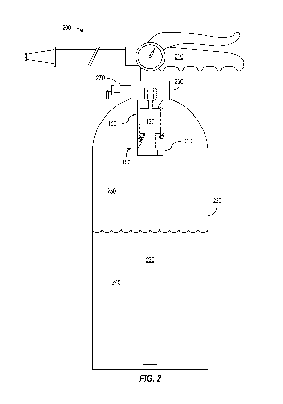
[0013] Fig. 2 illustrates a fire suppression system 200 in accordance with
an
implementation using in-tank manifold 100 of Fig. 1. In system 200, manifold
100
attaches to a squeeze handle 210. Fig. 2 shows a specific implementation in
which
manifold 100 is threaded into a fitting 260 for a pressure relief valve, and
fitting 260
attaches squeeze handle 210 to a tank 220. Alternatively, the foam outlet of
manifold 100
may directly thread into squeeze handle 210. In either case, squeeze handle
210 with or
without fitting 260 attaches to and seals tank 220 in a conventional manner
for fire
extinguishers so that tank 220 may be pressurized to a desired working
pressure while
manifold 100 is within tank 220. As shown in Fig. 2, tank 220 includes a
single
compartment that is partially filled with an aqueous foam concentrate 240,
e.g., Class A
foam concentrate, aqueous film forming foam (AFFF) concentrate, or polar
solvent foam
concentrate mixed with water, and is pressurized with a gas 250, e.g., air at
about 100 to
300 psi or more. Tank 220 may, for example, be a 2 1/2 gallon stainless steel
tank such as
commonly employed for some fire extinguishers, but tank 220 may alternatively
be of any
size and construction capable hold liquid and gas under suitable pressure.
[0014] Manifold 100 in the illustrated embodiment is near the top of tank
220 and in
the gas filled portion of tank 220, and a dip tube 230 threads into the liquid
inlet of
manifold 100 and extends into a liquid filled portion of tank 220 and
particularly down to
near the bottom of a tank 220. In operation, a user depresses a portion of
squeeze handle
210 opening a valve so that the higher pressure in tank 220 forces liquid 240
and gas 250
toward the lower pressure outside tank 220. Liquid 240 particularly flows up
dip tube 230
and into expansion chamber 130. Since manifold 100 and its gas inlets are
above the level
of liquid 240, gas 250 flows through the gas inlets of manifold 100 into
mixing/expansion
chamber 130. The mixing of liquid 240 and gas 250 in chamber 130 forms fire
suppressant foam that exits through squeeze handle 210 and a nozzle that can
direct the
foam for fire suppression.
[0015] Tanks used in current pressurized fire extinguishers are commonly
hydro-tested
-4-
CA 03023652 2018-11-08
WO 2017/165309 PCT/US2017/023241
up to 300 psi and are rated for working pressures of about 100 psi to 160 psi.
Operating
system 200 at a higher pressure up to 200 or 300 psi or more allows system 200
to be
filled with a greater volume of liquid 240, while pressure of gas 250
maintains a strong
stream of foam from system 200. System 200 may thus be able to provide more
suppressant foam than do conventional CAFS extinguishers.
[0016] Fig. 3 shows an in-tank manifold 300 including a bottom piece 310
and a top
piece 320 in accordance with another implementation. Manifold 300 may include
many of
the same features as described above for manifold 100. In particular, pieces
310 and 320
connect together to form an expansion chamber 130 having an liquid inlet 132
and a foam
outlet 136, which may have the characteristics described above. Fig. 3 further
illustrates
how manifold 300 may include multiple gas inlets 331, 332, 333, and 334 having
fixed or
drilled sizes, which may be different. For example, one inlet 331 may provide
the smallest
diameter or area gas inlet to expansion chamber 130, inlet 332 may be larger
than inlet
331, inlet 333 may be larger than inlet 332, and inlet 334 may provide the
largest diameter
or area gas inlet to chamber 130. The increasing size may be in an order that
directs a
mixing circulation of liquid and gas in chamber 130.
[0017] Fig. 3 also illustrates how manifold pieces 310 and 320 may be
threaded
together to create a chamber 130 that is larger than its inlets and outlets.
[0018] Fig. 4 shows an in-tank manifold 400 that may include many of the
same
features as described above for manifold 100 or 300. In particular, pieces 410
and 420 of
manifold 400 connect together to form an expansion chamber 130 having an
liquid inlet
132 and a foam outlet 136, which may have the characteristics described above.
Manifold
400 also includes a series of threaded gas inlets 431, 432, 433, and 434 in
manifold pieces
410 and 420 and sized for installation of replaceable jets 441, 442, 443, and
444. For
example, an Allen wrench can be used to install jets 441 to 444 in respective
gas inlets 431
to 434 or remove the jets from the gas inlets. Each installed jet 441, 442,
443, and 444 has
an orifice that limits the gas or air flow through the corresponding inlet
431, 432, 433, and
434. The orifices in jets 441, 442, 443, and 444 may all be the same size, or
one or more
of jets 441, 442, 443, and 444 may have different sizes. In some
configurations, one or
more of jets 441, 442, 443, and 444 may be omitted, and the diameters of
inlets 431, 432,
433, and 444 without a jet defines a maximum orifice size. In one
configuration, the
-5-
CA 03023652 2018-11-08
WO 2017/165309 PCT/US2017/023241
orifices may be about 1/16 inch in diameter or smaller and inlets 431 to 424
may be about
1/4 inch in diameter. Depending on the orifice size or sizes in the installed
jets 441, 442,
443, and 444, manifold 400 may produce a drier or wetter foam. In particular,
jets with a
smaller orifices may be employed when a wetter foam is desired, or jets with
larger
orifices may be employed when a drier foam is desired.
[0019] Jets 441, 442, 443, and 444 installed in inlets 431, 432, 433,
and 434 may be
chosen to achieve the same effects as described above for manifold 300 of Fig.
3. For
example, in the direction of circulation in chamber 130, jet 441 may have the
smallest
diameter or area orifice, jet 442 may have a larger orifice than does jet 441,
jet 443 may
have a larger orifice than does jet 442, and jet 444 may have the largest
diameter or area
orifice. The increasing size of the orifices and increasing air flows that
result may be in an
order that directs a mixing circulation of liquid and gas in chamber 130.
[0020] Fig. 4 also illustrates how manifold pieces 410 and 420 may be
tight fit and
pressed together to create an expansion chamber 130 that is larger than inlets
and outlets
of expansion chamber 130. In particular, one manifold piece 410 or 420 may
have a male
mating portion with an outside diameter that is the same as or slightly larger
than an inside
diameter of a female mating portion of the other manifold piece 420 or 410.
During
manufacture of manifold 400, mating portions of manifold pieces 410 and 420
may be
aligned, and a vise or press may apply pressure to force one mating portion
into the other.
If desired manifold 410 or 420 with the female mating portion may be heated.
In any case,
the tight fit may hold manifold pieces together without need of threads or a
set screw.
[0021] Figs. 5A and 5B show exterior views of a manifold 500 that may
have the same
features as the manifolds described above. In particular, manifold 500
includes two pieces
110 and 120 that engage each other to create a mixing or expansion chamber
having one
or more liquid inlet 132, one or more gas inlet 134a and 134b, and one or more
foam
outlet 136. Gas inlets 134a and 134b in manifold 500 extend through piece 110
or 120 to
the expansion chamber and are threaded. Accordingly, jets may be screwed into
either gas
inlets 134a and 134b to control the size of the orifices through which gas
flows into the
expansion chamber. Manifold 500 further includes pockets 534a and 534b that
may have
the same threading as gas inlets 134a and 134b but do not extend through piece
110 or 120
to the expansion chamber. Accordingly, no gas flows through pocket 534a or
534b, but a
-6-
CA 03023652 2018-11-08
WO 2017/165309 PCT/US2017/023241
jet may be screwed into either pocket 534a or 534b for storage when not in
use. For
example, manifold 500 may come with multiple jets with different size orifices
for use in
inlets 134a and 134b, and a user may select jets according to whether a drier
or a wetter
foam is desired. The user can then screw selected jets into gas inlets 134a
and 134b and
screw the spare jets into pockets 534a and 534b. Alternatively, manifold 500
may have a
single jet for each gas inlet 134a or 134b and may give a user the option to
use the jets in
gas inlet 134a and 134b to restrict air flow into the mixing or expansion
chamber or screw
the unused jets into pocket 534a or 534b for unrestricted flow through gas
inlets 134a or
134b.
[0022] Although particular implementations have been disclosed, these
implementations are only examples and should not be taken as limitations.
Various
adaptations and combinations of features of the implementations disclosed are
within the
scope of the following claims.
-7-