Note: Descriptions are shown in the official language in which they were submitted.
84811179
- 1 -
Coupling element for an electrical switching device
The invention relates to a coupling element for an electrical
switching device.
In medium-voltage and high-voltage circuit breakers for AC voltage,
it is necessary that the electrical contacts are capable of opening
or closing within a half-cycle and in the process travel a
sufficiently large distance in order to build up or reduce the
necessary insulating clearance. In addition, the drive unit needs to
be capable, during closing of the switchgear assembly, of building
up and maintaining a required contact force within the permissible
time window. On opening, increased separation force may result from
partial welding of the two electrodes or the two switching contacts,
which are physically separated and electrically isolated with
respect to the switching contacts by the drive unit, which results
in relatively high masses and therefore high kinetic energy. During
a change in state of the contact, therefore, this in turn results in
a high degree of excess energy during closing or opening of the
contact, and this excess energy generally needs to be damped in a
complex manner in order to avoid so-called contact bounce.
In order to enable safe switching, a substantially higher drive
power is generally provided than would in principle be necessary for
the switching operation. This in turn results in an excess energy
which needs to be compensated for at the end of the switching
operation. For this compensation operation, in turn an additional
damping element is required.
The object of the invention consists in providing a coupling element
for opening or closing a switching contact for an electrical
switching device which, in comparison with the prior art, has a
lower requirement for mechanical energy in order to reduce contact
bounce.
CA 3023786 2019-12-20
84811179
- 2 -
The object is achieved by a coupling element for an electrical
switching device.
The coupling element according to the invention has a first
switching contact for opening and closing an electrical contact
having a second switching contact. In this case, the coupling
element comprises a rod-shaped, elongate winding body, with the
first switching contact being arranged at one end of said winding
body. In addition, the coupling element comprises a rotating body,
through which the winding body extends. In this case, the rotating
body comprises two sides, of which one side faces one end of the
winding body and the other side faces the other end of the winding
body having the switching contact. The rotating body is in this case
mounted rotatably on the winding body, and in this case the winding
body is mounted so as to be capable of translational, i.e. linear,
movement along its longitudinal axis. In this case, at least one
cord, which may be in the form of a rope or a wire rope, for
example, is arranged on each of the two sides of the rotating body
between the rotating body and the winding body in such way that
winding and unwinding of the cords on the winding body takes place
by virtue of opposite rotational movements of the rotating body,
which results in a translational movement of the winding body. In
addition, the rotating body is characterized by the fact that at
least two springs are coupled in such a way that a spring force
always acts on the rotating body in both directions of rotation,
wherein a lock is provided which locks the rotating body in end
positions of the translational movement of the winding body.
In order to keep the resultant excess energy after a change in state
of the coupling element as low as possible, it is helpful to
minimize the moving masses and to ensure as smooth a movement
profile of the entire coupling element as possible.
CA 3023786 2019-12-20
= CA 03023786 2018-11-09
PCT/EP2017/058739 - 3 -
2016P07709W0US
This applies in particular to the starting phase and to the
stop phase of the switching operation. By virtue of the present
invention, the masses of the kinematics are reduced by virtue
of torsional loading and bending loading being dispensed with
and there correspondingly only being compressive and tensile
loading. This is achieved in particular by the smooth movement
profile, with the result that a resonator, in this case
configured in the form of the two springs which are coupled to
the rotating body, is realized.
In a further configuration, a freewheel is provided which is
coupled to the rotating body and which permits only one
direction of rotation of the rotating body. This freewheel is
in the form of a corresponding ball bearing, for example, which
is only rotatable in one direction, and it is used to ensure
that, despite spring forces acting on the rotating body in an
end position of the winding body, in principle when a
corresponding signal is triggered only one direction of
movement of the rotating body and therefore also only one
direction of movement of the winding body is possible. In this
case, it is additionally expedient that two freewheels are
provided, of which in each case one is activated, and
switchover of the activation between the two freewheels takes
place in the end positions of the winding body. Thus, it is
ensured that in each case only one direction of movement of the
winding body and therefore the first switching contact is
possible.
The lock which locks the rotating body in the position in which
an end position of the translational movement of the winding
body is present is preferably released by a corresponding
actuator. In this case, the actuator can respond to a
corresponding signal, for example a control signal, which
initiates opening or closing of the switching contact.
CA 03023786 2018-11-09
PCT/EP2017/058739 - 4 -
2016P07709W0US
In one advantageous configuration, in the end position of the
winding body in which the contacts are closed, a contact-
pressure force of the first contact against the second contact
is exerted by virtue of the spring force acting on the rotating
body. In this case, an offset force is applied to the first
switching contact, with it being possible for the desired
contact force of the electrodes to be determined with the aid
of said offset force.
Therefore, in practice small quantities of energy in the
resonator system between the springs and the rotating bodies
are lost as a result of friction, for example in the springs or
the cords, with the result that, after a certain number of
opening and closing operations of the coupling element, energy
needs to be introduced into the system. This energy is
introduced into the system by mechanical tensioning of the
springs.
Yet further features of the invention will be described in the
following exemplary embodiments with reference to the following
figures. These are purely exemplary configurations which do not
form part of the scope of protection. In the figures:
Figure I shows a coupling element having a rotating body and a
winding body and two switching contacts, wherein the
two switching contacts are located in an open end
position,
Figure 2 shows a corresponding coupling element as shown in
figure 1 in a mid-position, and
Figure 3 shows a coupling element as shown in figure 1 in
which the switching contacts are closed.
The invention will be explained below with reference to a
coupling element 2, which serves the purpose of opening and
CA 03023786 2018-11-09
PCT/EP2017/058739 - 5 -
2016P07709W0US
closing the switching contacts 4, 6 in a vacuum interrupter.
Nevertheless, the coupling element according to the invention
can also be used in other switching devices for opening and
closing an electrical contact.
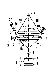
Figures 1 to 3 show a variant of a coupling element 2 according
to the invention. By means of the coupling element 2, a contact
system consisting of the disk-shaped switching contacts 4 and 6
is actuated, wherein the switching contact 4 is moved relative
to the switching contact 6 for this purpose. On contact-making
between the two switching contacts 4 and 6, an electrical
circuit is closed and a current flow via the electrically
conductive rod-shaped winding body 8 (explained further below)
and the contact system of the switching contacts 4 and 6 is
effected. This current flow can be interrupted again by opening
of the contact system by virtue of the two switching contacts 4
and 6 being moved apart from one another.
The switching contact 4 is fastened to a lower end of the
winding body 8, which will also be referred to below as the
winding bar. The winding body 3 is linearly, i.e.
translationally, displaceable, wherein it is guided along its
longitudinal axis, but cannot be twisted in the process. A
rotating body 10 is mounted rotatably on the winding body 8,
i.e. the rotating body can rotate on the winding body. For this
purpose, the rotating body 8 has a bore, through which the rod-
shaped winding body 8 protrudes. In this case, a bearing 13 is
provided between the winding body 8 and the rotating body 10,
with the result that the rotation of the rotating body 10
proceeds with as little friction and as few losses as possible.
In this case, the rotating body 8 in this example comprises two
disks or sides 11 and 12 which are spaced apart from one
another. In this embodiment, the bearing 13 is illustrated
schematically between these two sides 11 and 12 of the rotating
CA 03023786 2018-11-09
PCT/EP2017/058739 - 6 -
2016P07709W0US
body, said bearing being intended to illustrate that the
rotating body 10 is mounted rotatably on the winding body 8.
Figure 1 shows a position of the coupling element 2, wherein
the contacts 4 and 6 are open when there is as great a distance
as possible between them. This distance is denoted by the end
position E with respect to the position of the contact 4.
Figure 2 shows a mid-position between the end position E and
the end position E' illustrated in figure 3, in which the
contacts 4 and 6 are closed and a current flow can take place
via the contacts.
Beginning with the position of the end position E in figure 1,
the closing operation of the coupling element 2 will now be
described. In this case, it should also be mentioned that the
rotating body 10 is coupled to two springs 18 (in this
example). The springs 18 are designed for tensile loading and
in this case are fastened at one end to the rotating body 10
and fixed at another end to a fixing point 24 outside the
coupling element 2. In the end position E, in which a spring 18
has a greater pretension than the spring 18', a lock is
provided, which in turn is connected to an actuator 22. In this
example, the lock 20 is illustrated very schematically by a
rod; the lock 20 may be in the form of two toothed rings
engaging in one another, for example, which is not explicitly
illustrated here for reasons of better clarity.
In addition, the coupling element comprises cords 16 and 16',
which are fastened between the rotating body 10 and the winding
body 8, preferably provided with a certain pretension. The
cords 16 are in this case each fitted to the winding body 8 and
are fastened at a second fastening point as far outwards as
possible on the disks 11 and 12 or on the upper and lower sides
11 and 12 of the rotating body 10. In this case, cords are
intended to mean overall flexible structures, such as ropes,
wire ropes or aramid fibers, for example, which have a high
= CA 03023786 2018-11-09
PCT/EP2017/058739 - 7 -
2016P07709WOUS
modulus of elasticity on one side in order to achieve as fixed
a pretension between the winding body 8 and the rotating body
as possible.
In the example shown in figure 1, the cords 16' are wound
around the winding body through a plurality of revolutions in
the lower region between the side 12 of the rotating body 10
and the switching contact 4. In the upper region of the
coupling element, i.e. above the side 11 of the rotating body
10, the cords 16 are not twisted in the position of the end
position E shown in figure 1. If the lock 20 is opened, for
example as a result of a signal which it is passed to the
actuator 22, a rotary movement of the rotating body is produced
owing to the pretension of the springs 18 and 18', which are
overall configured in such a way that a resonator is produced,
and, as a result of this rotary movement, the cords 16' unwind
in the lower region of the winding body 8 and, conversely, the
cords 16 are wound on in the upper region, above the rotating
body 10, on the winding body. This position is illustrated in
figure 2. In the position shown in figure 2, the springs 18 and
18' are also present substantially in a position of
equilibrium, wherein a pretension of the springs 18 and 18' is
present in this case too. This position of equilibrium shown in
figure 2 is overcome by virtue of the effect of the two springs
as resonator and, as shown in figure 3, the position of the end
position E' in which the two switching contacts 4 and 6 are
closed is set.
In this case, the system is configured with respect to the
pretensions of the individual springs 18 and 18' in such a way
that not only is contact produced between the contacts 4 and 6,
but also an offset force, i.e. an additional contact-pressure
force, acts on the switching contact 6 owing to the winding
body 8 and the switching contact 4. When the end position E' is
reached, the lock 20, in turn triggered by the actuator 22,
CA 03023786 2018-11-09
PCT/EP2017/058739 - 8 -
2016P07709WOUS
engages in the rotating body 10, with the result that the
position of the rotating body 10 is maintained.
In the movement sequence illustrated between figures 1 and 3,
it is shown how, owing to the rotation of the rotating body 10,
a rotational movement is converted into a translational
movement of the winding body 8 and therefore also of the
switching contact 4 by virtue of winding of the cords 16. The
translational or else linear movement of the winding body 8 can
take place in both directions. The closing operation described
here can be described in the reverse direction starting from
figure 3, through the position in figure 2, back to figure 1,
wherein a translational movement of the winding body 8 along
its longitudinal axis 14 in the direction of the end position E
is completed.
Since the spring pair 18 and 18' acts as resonator, this
movement can very often proceed without any considerable
friction losses. The friction losses are therefore very low
since the friction which is transmitted via the cords 16 and
16' is likewise low and as good positioning of the rotating
body with respect to the winding body 8 as possible takes
place.
The rotary movement of the rotating body 10 is configured in
such a way that the rotating body performs in each case a
rotation of approximately 90 in each direction during an
opening and a closing operation. In this case, the switching
time, i.e. the time which is required by the coupling element
to move from the end position E' to the end position E, and
vice versa, is dependent on the stiffness of the springs 18
used and the inertia, i.e. the mass of the rotating body 10,
which also acts as flywheel. The angular velocity U of the
rotating body 10 is in this case directly proportional to the
root of the ratio of the spring stiffness, i.e. the spring
CA 03023786 2018-11-09
PCT/EP2017/058739 - 9 -
2016P07709W0US
constant K, and the mass m of the rotating body 10, expressed
by way of example by the equation
(K/m) '5.
In this case, the energy of the rotating body is set in such
way that the desired Q, i.e. the desired angular velocity, and
the desired switching time for the respective switching
operation results, wherein approximately 95% of the total
energy of the system flows into the switching operation. Owing
to the described switching system or coupling element which
operates with very low losses, in this case, in an exemplary
switching operation, approximately 1.5 J of energy is lost in
the system. In a conventional switching operation using a
conventional drive, given the same power and a comparable size
of the coupling element 20 to 30 times the amount of energy per
switching operation is lost. This means that this energy is
lost when the two switching contacts 4 and 6 meet, which
results in this energy separating the switching contacts from
one another and bringing them together again a plurality of
times in the microscopic range in a so-called bouncing
operation, in a similar way to the way in which a hammer acts
as it hits an anvil. This bouncing operation is extremely
undesirable during switching of the high-voltage installation
since it is not possible for contact to be built up uniformly
and quickly as a result of this bouncing operation. By virtue
of the coupling element shown in figures 1 to 3 which operates
with low energy losses, this bouncing operation is reduced to a
minimum.
Since the system of the coupling element 2 switches with such
low losses, it is possible to implement a large number of
switching operations given a corresponding pretension of the
springs 18 and 18'. In this case, the system is preferably set
in such a way that as many switching operations can be
performed as would generally occur between two maintenance
CA 03023786 2018-11-09
PCT/EP2017/058739 - 10 -
2016P07709W0US
intervals of the switchgear assembly which take place in any
case. Thus, with routine maintenance, mechanical tightening,
i.e. pretensioning, of the springs 18 and 18' can take place by
over-rotation of the rotating body 8 (flywheel). The tightening
can take place, for example, manually corresponding to a
mechanical clock or with the aid of an electric motor.
Furthermore, two freewheels are also arranged in the region of
the bearing 13 (illustrated purely schematically), and the
function of the freewheels consists in permitting a rotational
movement of the rotating body 10 only in one direction, namely
in the direction which is the only desired direction with
respect to the respective end position E or E'. These
freewheels, which are not explicitly illustrated here, act
hand-in-hand with the lock 20, with the result that, when the
respective lock 20 is applied, in the end position E, for
example, switching only takes place into that freewheel which,
owing to the corresponding rotation, permits a translational
movement along the axis 14 of the winding body 8 in the
direction of the lower end position, i.e. the closed end
position E'. In the end position E' shown in figure 3, in turn
exclusively the rotational movement in the opposite direction
and therefore a translational movement upwards in the direction
of the end position E is permitted. The freewheel is a ball
bearing, which permits only one direction of rotation and
blocks the opposite direction of rotation.