Note: Descriptions are shown in the official language in which they were submitted.
APPARATUS FOR PRODUCING A FIRE
SPECIAL EFFECT
[Para 1]
FIELD OF THE INVENTION
[Para 21 The present invention is directed to a special effect device and,
more specifically,
to a special effect for producing a simulated flame or fire effect.
BACKGROUND OF THE INVENTION
[Para 31 The use of a simulated fire or flame is desirable in many
applications. For
instance, in many theme park attractions (e.g., volcano, battle scene and
disaster scenes), the use
of a simulated flame or fire is preferred relative to a real flame or fire for
a number of reasons.
For instance, a real flame or fire must typically be located a substantial
distance from an
audience to prevent members of the audience from coming into contact with the
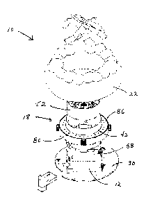
fire or flame.
Further, with respect to attractions that are located indoors, a real flame or
fire produces heat and
smoke that typically require additional air conditioning and ventilation. In
contrast, several types
of simulated flame or fire effects can be located close to an audience and do
not typically impose
the air conditioning and ventilation requirements of a real flame or fire.
[Para 41 There are many types of devices for producing simulated flames or
fire. For
example, one type of device blows strips of colored material, such as silk, up
into the air and
shines an appropriately colored light onto the strips. From a distance, these
devices provide a
reasonably convincing simulated flame or fire. At the other end of the
spectrum are devices that
provide a television or video monitor with a signal of a pre-recorded fire or
flame. Such devices
are impractical in theme park applications that require a flame or fire that
extends over a distance
that is greater than the typical width and height of a video monitor or
television. Yet a further
type of device involves the use of a screen of atomized water and the
projection of an image or
light on the screen that creates the illusion of a flame or fire. Also known
are devices that
-1-
Date Recue/Date Received 2020-06-26
generate use theatrical smoke or steam in creating the illusion of a fire or
flame. Among these
devices are the devices disclosed in U.S. Pat. Nos. 6,685,574, 6,802,782,
6,953,401, and
7,762,897.
SUMMARY OF THE INVENTION
[Para 5] The invention disclosed herein is directed to an apparatus for
creating a fire or
flame special effect using steam or theatrical smoke where the apparatus needs
to facilitate the
illusion of a fire/flame over a relatively large two-dimensional area. In such
an application, a
relatively even distribution of steam or theatrical smoke is required to
produce a convincing
fire/flame effect. An example of an application requiring a simulated
fire/flame needed over a
relatively large two-dimensional area and a relatively even distribution of
steam or theatrical
smoke to be convincing is a simulated campfire that is two to three feet in
diameter.
[Para 6] In one embodiment, the apparatus includes a pipe for providing a
stream of gas,
first chamber for receiving a stream of gas the pipe and a second chamber that
surrounds the first
chamber. As such, the second chamber can be characterized as an annular
chamber. The second
chamber also defines an annular closed-loop slot for directing a closed-loop
sheet of gas into the
ambient atmosphere. As should be appreciated, the sheet of gas has a somewhat
opaque
characteristic that, when light is projected onto the sheet of gas, reflects
that light and thereby
facilitates the creation of a simulated flame or fire. In this regard, two
gaseous substances that
can be used to produce the simulated flame or fire effect are steam and
theatrical smoke. The
apparatus also includes a passageway for conveying the gas from the first
chamber to the second
chamber. The passageway can also be characterized as being annular and can be
a single
continuous passageway or comprised of multiple sub-passageways that define a
closed-loop. In
operation, the apparatus causes a relatively even steam or theatrical smoke
received in the first
chamber to pass through the passageway and through the annular closed-loop
slot. A lighting
structure that creates the appropriately colored light or lights is projected
onto the closed-loop
sheet of gas that exits the closed-loop annular slot to establish the desired
color or colors for the
fire/flame effect. For instance, in the case of a simulated campfire, the
lighting structure will
typically project red and yellow colors onto the closed-loop sheet of gas.
[Para 7] Depending on the application, the closed-loop sheet of gas may need
to be
modulated to create a convincing simulated flame/fire effect. In one
embodiment, the apparatus
-2-
CA 3023901 2018-11-13
further includes an air modulator for blowing air at the closed-loop. In a
particular embodiment,
the air modulator includes a third annular chamber that is positioned adjacent
to the closed-loop
annular slot and defines a plurality of orifices that are positioned to direct
streams of air at the
closed-loop sheet of gas exiting the closed-loop annular slot. The air
modulator employs one or
more fans to force air into the third annular chamber and out through the
orifices. In another
embodiment, the apparatus includes a "skin" with one or more portions of the
skin positioned
adjacent to closed-loop annular slot so as to affect movement of the gas
exiting the slot. For
instance, in the case of a "campfire skin," the skin may include simulated
logs or rocks that are
positioned adjacent to the annular closed-loop slot and affect the manner in
which those portions
of the annular sheet of gas adjacent to the logs or rocks move after exiting
the annular closed-
loop slot.
[Para 8] In an embodiment of the apparatus in which theatrical smoke is
employed in
creating the simulated flame/fire effect, the relatively even distribution of
the flow of the
theatrical smoke from the first chamber to the second chamber has been found
to be enhanced by
positioning the end of the pipe that injects the theatrical smoke into the
first chamber such the
smoke is directed at the bottom surface of the chamber. Further, a fan is
employed to facilitate
the movement of the theatrical smoke out of the first chamber, through the
passageway and into
the second chamber. In contrast, in an embodiment of the apparatus in which
steam is employed
in creating the simulated flame/fire effect, the relatively even distribution
of the flow of the
steam from the first chamber into the second chamber has been found to be
enhanced by
directing the steam away from the bottom surface of the chamber. In a
particular embodiment,
the steam is also distributed within the first chamber by employing a manifold
with multiple
orifices for injecting the steam at various locations throughout the first
chamber. In a particular
embodiment, the manifold is located farther from the bottom surface of the
first chamber than the
passageway.
BRIEF DESCRIPTION OF THE DRAWINGS
[Para 9] FIGS. 1A and 1B respectively are a top view and side view of an
embodiment of
a special effect device for producing a simulated flame or fire effect using
theatrical smoke to
simulate a campfire;
CA 3023901 3023901 2018-11-13
[Para 10] FIG. 1C is an exploded view of the embodiment of the special effect
device
shown in FIGS. 1A and 1B;
[Para 111 FIG. 1D is a cross-sectional view of the embodiment of the special
effect device
shown in FIGS. IA and 1B;
[Para 12] FIGS. 2A-2C respectively are perspective, top, and side views of the
special
effect device shown in FIGS. 1A and 1B without the exterior "skin" that causes
the device to
appear as a campfire;
[Para 13] FIG. 2D is an exploded view of the special effect device, as shown
in FIGS. 2A-
2C;
[Para 14] FIG. 2E is a perspective view of the special effect device shown in
FIGS. 2A-2C;
[Para 151 FIGS. 2F-2G are cross-sectional views of the special effect device,
as shown in
FIGS. 2A-2C;
[Para 16] FIGS. .3A-3C respectively are an exploded view, perspective view,
and cross-
sectional view of a second embodiment of a device for creating a flame effect
using theatrical
smoke; and
[Para 17] FIGS. 4A-4E respectively are an exploded view, perspective view,
side view, side
cross-sectional view, and vertical cross-section view of an embodiment of
device for creating a
flame effect using steam.
DETAILED DESCRIPTION
[Para 18] With reference to FIGS. 1A-1D and 2A-2G, an embodiment of a special
effect
device 10, which is hereinafter referred to as device 10, that uses theatrical
smoke to produce a
simulated flame or fire effect is described. Generally, the device 10 includes
a theatrical smoke
generator 12, a smoke distributor and pressurizer chamber 14 (hereinafter
chamber 14), a smoke
curtain chamber 16 (hereinafter chamber 16), a smoke curtain disrupter system
18, a light system
20, and an outer skin 22 that conveys the appearance of the wood and rocks
that might be
associated with a campfire. Generally, operation of the device 10 involves the
production of
theatrical smoke by the smoke generator 12 and the reception of the produced
smoke in the
chamber 14. The chamber 14 operates to distribute the smoke over a 360
angular extent and
apply pressure to the smoke so as to move the smoke into the smoke curtain
chamber 16. The
smoke curtain chamber 16 operates so that the smoke received from the chamber
14 is directed
-4-
CA 3023901 2018-11-13
so as to produce a relatively thin curtain of upwardly extending smoke over a
360 angular
extent. The smoke curtain disrupter system 18 operates to produce moving air
that is applied to
the thin curtain of upwardly extending smoke produced by the smoke curtain
chamber 16 so as to
disrupt the curtain of smoke, thereby causing the smoke to move in a manner
similar to the
movement associated with an actual flame or fire. The light system 20 produces
light of a
desired color or colors that is applied to the curtain of smoke exiting the
chamber 16 so as to
simulate the color or colors of an actual fire or flame. For the simulation of
a campfire, the light
system 18 produces red-orange light and yellow light with the red-orange light
applied to the
lower portion of the smoke curtain and the yellow light applied upper portion
of the smoke
curtain. However, a different color or combination of colors can be produced
and applied to the
curtain of smoke, if needed or desired.
[Para 19] With continuing reference to FIGS. 1A-1D and 2A-2F, the device 10 is
described
in greater detail. The device 10 includes a base 30 for engaging a ground
surface and supporting
other elements of the device, an outer housing 32 that is supported by the
base 10, a lower inner
housing 34 that is supported by the outer housing 32, an upper inner housing
36, a light housing
38, and a conduit 40 for transporting theatrical smoke from the smoke
generator 12 into the
chamber 14. The outer housing 32 includes a side wall 42 and a bottom wall 44.
The lower
inner housing 34 has five side walls 48A-48E and is supported such that bottom
edge of each of
the side walls is spaced a small distance from the bottom wall 44 of the outer
housing 32 so as to
define a gap 50. The upper inner housing 36 includes a side wall 52 and a
bottom wall 54. The
bottom wall 54 defines an opening 56 for accommodating a fan 58 that is used
to pressurize the
housing 14.
[Para 20] The smoke distribution and pressurizer chamber 14 is formed from the
inner
lower housing 34, a portion of the bottom wall 44 of the outer housing 32, and
a portion of the
bottom wall 54 of the upper inner housing 36.
[Para 21] The smoke curtain chamber 16 if formed by the side wall 42 of the
outer housing
32, a portion of the bottom wall 44 of the outer housing 32, the side walls
48A-48E of the lower
inner housing 34, the side wall 52 of the upper inner housing 36, and a
portion of the bottom wall
54 of the upper inner housing 36. A portion of the side wall 42 of the outer
housing 32 and the
side wall 52 of the upper inner housing 36 define a slot 60 with a 3600 extent
and an outlet port
62. In operation, the slot 60 receives theatrical smoke and conforms the smoke
so that the smoke
-5-
CA 3023901 2018-11-13
exiting the outlet port 62 extends upwardly in a thin curtain in the absence
of obstructions above,
or disturbances to the atmosphere above, the outlet port 62.
[Para 22] The conduit 40 extends from a first end 64 that is operatively
engaged to the
smoke generator 12 to a second end 66 that is disposed in the chamber 14. In
the illustrated
embodiment, the conduit 40 extends through a first hole 68 in the outer
housing 32 and through a
second hole 70 in the lower inner housing 34. If needed or desired, any gap
between the conduit
40 and the outer housing 32 and any gap between the conduit 40 and the lower
inner housing 34
can be closed with sealant, gaskets, or other devices known to those skilled
in the art. The
second end 66 of the conduit 40 is disposed in the chamber so that the
theatrical smoke exiting
the conduit is directed at the bottom wall 44 of the outer housing 32 and
directed at a location
that is approximately the geometric center of the pentagon defined by the
sides wall 48A-48E of
the lower inner housing 34 or the circle defined by the side wall 42 of the
outer housing 32.
[Para 23] The light housing 38 includes a side wall 72 and a porous cross-wall
74 that each
serve to support a number of light fixtures. More specifically, the light
housing 38 supports
high-intensity LED light fixtures 76A-76J that are substantially located
between the light
housing 38 and the side wall 52 of the upper inner housing 36. Further, the
porous cross-wall 74
of the light housing 38 supports one or more high-intensity LED light fixtures
78. The porous
cross-wall 74 is sufficiently porous so that the fan 58 can draw air from the
ambient environment
through the wall and apply this air to the pressurization of the chamber 14.
[Para 24] The device 10 further includes a toroidal housing 80 that engages
the outer
surface of the side wall 42 of the outer housing 32 and four fans 82A-82D. The
toroidal housing
80 defines four fan ports 84A-84D that respectively conduct the air streams
produced by the fans
82A-82D into the housing and a number of discharge holes 86 for discharging
air from within
the housing in a direction that can be used to disrupt the thin curtain of
theatrical smoke
produced adjacent to the outlet port 62 of the slot 60. In operation, the fans
82A-82D serve to
inject sufficiently pressurized air into the interior of the housing 80 so
that roughly equal streams
of air exit the discharge ports 86. In operation, the steams of air coming out
of the discharge
holes 86 interact with portions of the outer skin (e.g., the simulated logs
and rocks) so as to
produce a flow of air that disrupts the curtain of smoke produced at the
outlet port 62 of the slot
in a manner that substantially simulates a real fire or flame.
-6-
CA 3023901 2018-11-13
[Para 25] The device 10 further includes a power supply 88 for providing power
to the
smoke generator 12, fan 58, the lights 76A-76J, light(s) 78, and fans 82A-82D.
[Para 261 In operation, the smoke generator 12 produces smoke that is injected
into the
chamber 14. The conduit 40 causes the injection of the smoke into the chamber
14 to be directed
at the bottom wall 44 of the outer housing 32 and substantially in the center
of the area defined
by the side walls 48A-48E of the lower inner housing 34. The pressurizing
stream of air
produced by the fan 58 and injected into the chamber 14 results in a roughly
even distribution of
the theatrical smoke through the gap 50 and into the chamber 16. Due to the
pressure produced
by the fan 58, the theatrical smoke is driven towards and through the slot 60
such that a thin
curtain of smoke is produced adjacent to the outlet port 62 of the slot. The
lights 76A-76J and 78
are used to project the desired color or colors of the light onto the curtain
of smoke so as to
simulate a flame or fire. Further, the fans 82A-82D and the toroidal housing
80 operate to
produce streams of air around and adjacent to the outlet port 62 of the slot
that disrupt the curtain
of smoke in a fashion that simulates a flame or fire.
[Para 27] It should be appreciated that the various chambers and housings
associated with
the device 10 can be realized in a number of different ways. Further, the
orientation and/or size
of various elements of the device 10 can be altered to accommodate a
particular application. For
instance, an outer skin that simulates a structure, such as a house, could be
employed in place of
the campfire simulating outer skin 22. Alternatively, the outer skin 22 could
be eliminated in
certain applications in which the device need only be positioned adjacent to
some other structure
to be effective.
[Para 281 With references to Figs. 3A-3C, a second embodiment of a special
effect device
that uses theatrical smoke to produce a simulated flame or fire effect,
hereinafter device 100, is
described. Device 100 has many of the same elements as are in device 10.
Consequently,
elements of device 100 that substantially correspond to elements in device 10
will be given the
same reference numbers. Device 100 includes a smoke distributor and
pressurizer chamber 14
(hereinafter chamber 14), a smoke curtain chamber 16 (hereinafter chamber 16),
a smoke curtain
disrupter system 18, a light system 20, and an outer skin 22 that conveys the
appearance of the
wood and rocks that might be associated with a campfire (skins that have the
appearance of some
kind of fire event other than a campfire are feasible). Further, the chamber
14 receives theatrical
smoke that is conveyed from a theatrical smoke generator 12 to the chamber 14
via a conduit or
-7-
CA 3023901 2018-11-13
pipe 40. A fan 58 that causes air to pass through an opening 56 into the
chamber 14 is used to
pressurize the chamber so as to force the theatrical smoke received within the
chamber 14 to
move from chamber 14 to chamber 16 via a gap 50 and on into an annular slot
60. The theatrical
smoke exits the annular slot 60 at an annular output port 62 as an annular
sheet of theatrical
smoke. The smoke disrupter system 18 is used to modulate the annular sheet of
theatrical smoke
that exits the output port 62 so that the theatrical smoke takes on the
"shape" of the flame or
flames associated with a campfire, which is a wavy shape that tends to vary or
change over time.
Further, the light system 20 is used to project appropriately colored light
onto the annular sheet
of theatrical smoke exiting the output port 62 so as to have the color or
colors of a campfire
flame.
[Para 29] The device 100 includes a side wall 42 which forms a closed-loop, a
bottom wall
44 that engages the side wall 42, a side wall 52 that forms a closed-loop, and
a bottom wall 54
that engages the side wall 52. These side and bottom walls collectively
encompass the spaces
defined by the chamber 14 and the chamber 16, including the portion of chamber
16 that defines
the slot 60. The side wall 34, which also forms a closed-loop, separates
chamber 14 from
chamber 16. Due to the closed-loop nature of the side wall 34 and the side
wall 42, the chamber
16 surrounds the chamber 14. As such, chamber 16 can be characterized as an
annular chamber.
Notably, the bottom wall 44 is a bottom wall for both the chamber 14 and
chamber 16. Further,
the top wall 54 is a top wall for both the chamber 14 and the chamber 16. It
should be
appreciated that chambers that are separated from one another by a greater
distance and with
separate top walls and bottom walls are feasible. In such an embodiment, an
additional wall
located between side wall 42 and side wall 34 would likely be needed to define
the extent of
chamber 16. Further, the gap 50 would lengthen and likely have a more toroidal-
type of shape
that would require an annular structure extending between separated chambers
14 and 16.
[Para 30] The device 100 includes a number of structures that are not
discussed with respect
to device 10. Among these structures is a tank 102 for storing the liquid used
by the theatrical
smoke generator 12 to create theatrical smoke and providing the liquid to the
generator as
needed. Further, the device 100 includes a tank 104 for collecting spent
theatrical smoke that has
precipitated within the chambers 14 and 16 and drained out through a hole in
the bottom wall 44
to be collected in the tank 104. Further, the device 100 includes a shroud 106
that engages the
base 30 of the device 100. The device 100 also includes a portion of the skin
22 that simulates a
-8-
CA 3023901 2018-11-13
bed of embers, hereinafter ember portion 108. The ember portion 108 is made of
a translucent
plastic material that is appropriately shaped and colored to imitate a bed of
embers. In operation,
the bank of LED lights 78 projects light onto the underside of the ember
portion 108. Due to
colored nature of the ember portion 108, the ember portion 108 appears to have
the correct color
or colors of a bed of embers even though the LED lights 78 project white light
onto the underside
of the ember portion. The device 100 also includes a sound box 110 that is
adapted to provide an
audio signal of the "crackling" sounds associated with a campfire to a
speaker. The sound box
110 can be adapted to provide the sounds associated with different fire
effects, if needed or
desired. Further, the fans associated with the disrupter system 18 are adapted
to receive scent
packets that provide a "burning campfire" scent that is dispersed by the
disrupter system 18.
Packets that provide the other types of scents (e.g., barbecue) are also
feasible. It should be
appreciated that device 10 and other embodiments of such devices can be
modified to include
these elements. Also, it should be noted that the end of the conduit/pipe 40
located within the
chamber 14 does not direct theatrical steam at the bottom wall 44, as in
device 10.
[Para 31] With references to Figs. 4A-4E, an embodiment of a special effect
device that
uses steam to produce a simulated flame or fire effect, hereinafter device
200, is described.
Device 200 has many of the same elements as are in devices 10 and 100.
Consequently,
elements of device 200 that substantially correspond to elements in device 10
or device 100 will
be given the same reference numbers. Device 200, because steam is used in
creating a simulated
flame effect, does not include many of the theatrical smoke elements present
in devices 10 and
100. Among the elements present in devices 10 and 100 that are not present in
device 200 are a
theatrical smoke generator 12, a tank 102 for storing the liquid used by the
theatrical smoke
generator 12 to create theatrical smoke, and a tank 104 for collecting spent
theatrical smoke.
[Para 32] While the elements of device 200 that substantially correspond to
the elements of
devices 10 and 100 have been given the same reference numbers, it should be
appreciated that
several of these elements have been renamed so to be identified as steam-
related elements rather
than smoke-related elements. The device 200 a steam distribution chamber 14
(hereinafter
chamber 14), a steam curtain chamber 16 (hereinafter chamber 16), a steam
curtain disrupter
system 18, a light system 20, and an outer skin 22 that conveys the appearance
of the wood and
rocks that might be associated with a campfire (skins that have the appearance
of some kind of
fire event other than a campfire are feasible). Further, the chamber 14
receives steam that is
-9-
CA 3023901 2018-11-13
conveyed from a boiler (not shown) to the chamber 14 via a conduit or pipe 40.
The energy
embodied in the steam received in the chamber 14 is sufficient to move the
steam from the
chamber 14 to the chamber 16 via a gap 50 and on into an annular slot 60. As
such, device 200
also does not include the fan 58 of devices 10 and 100. The steam exits the
annular slot 60 at an
annular output port 62 as an annular sheet of steam. The steam disrupter
system 18 is used to
modulate the annular sheet of steam that exits the output port 62 so that the
theatrical smoke
takes on the "shape" of the flame or flames associated with a campfire, which
is a wavy shape
that tends to vary or change over time. Further, the light system 20 is used
to project
appropriately colored light onto the annular sheet of theatrical smoke exiting
the output port 62
so as to have the color or colors of a campfire flame.
[Para 33] The device 200 includes a side wall 42 which forms a closed-loop
cylinder, a
bottom wall 44 that engages the side wall 42, a side wall 52 that forms a
closed-loop, and a
bottom wall 54 that engages the side wall 52. These side and bottom walls
collectively
encompass the spaces defined by the chamber 14 and the chamber 16, including
the portion of
chamber 16 that defines the slot 60. The side wall 34, which also forms a
closed-loop, separates
chamber 14 from chamber 16. Due to the closed-loop nature of the side wall 34
and the side
wall 42, the chamber 16 surrounds the chamber 14. As such, chamber 16 can be
characterized as
an annular chamber. Notably, the bottom wall 44 is a bottom wall for both the
chamber 14 and
chamber 16. Further, the top wall 54 is a top wall for both the chamber 14 and
the chamber 16.
It should be appreciated that chambers that are separated from one another by
a greater distance
and with separate top walls and bottom walls are feasible. In such an
embodiment, an additional
wall located between side wall 42 and side wall 34 would likely be needed to
define the extent of
chamber 16. Further, the gap 50 would lengthen and likely have a more toroidal-
type of shape
that would require an annular structure extending between separated chambers
14 and 16.
[Para 34] The device 200 also includes a steam manifold 202 for injecting
steam into the
chamber 14. The manifold 202 has a4:13-shape with a main tube 204 and two,
curved tubes 206A,
206B that each have multiple laterally extending orifices for venting steam
into the chamber 14
at multiple locations in the chamber 14 to facilitate a relatively even
distribution of steam within
the chamber 14. It is believed that steam manifolds with other shapes are
feasible, provided the
manifold multiple orifices that disperse the steam at multiple locations
throughout the chamber
14. The device 200 also includes a portion of the skin 22 that simulates a bed
of embers,
-10-
CA 3023901 2018-11-13
hereinafter ember portion 108. The ember portion 108 is made of a translucent
plastic material
that is appropriately shaped and colored to imitate a bed of embers. In
operation, the bank of
LED lights 78 projects light onto the underside of the ember portion 108. Due
to colored nature
of the ember portion 108, the ember portion 108 appears to have the
appropriate color or colors
of a bed of embers even though the LED lights 78 project white light onto the
underside of the
ember portion. Additionally, it has been found that in some embodiments of the
device 200 that
a flow straightener located in the gap 50 also facilitates an even
distribution of steam from the
chamber 14 to the chamber 16. With reference to Fig. 4D, a flow straightener
210 is located in a
portion of the gap 50. The flow straightener has a triangle-wave shape.
However, flow
straighteners with other shapes are also feasible. As should be appreciated,
the gap 50 is not
continuous but is composed of sub-gaps that are separated from one another by
stands 212 that
support the side wall 34 and other of the overly structure. The sub-gaps
define the annularly
extending gap 50. In other embodiments, it may be possible to eliminate the
stands 212 so that
the gap is continuous. The device 200 further includes a fan 214 that is
positioned to direct a
flow of air at the LED lights 78 to cool the lights. While the fan 214 is in
the same position as
the fan 58 used in devices 10 and 100, the fan 214 does not cause air to be
injected into the
chamber 14.
[Para 35] The foregoing description of the invention is intended to explain
the best mode
known of practicing the invention and to enable others skilled in the art to
utilize the invention in
various embodiments and with the various modifications required by their
particular applications
or uses of the invention.
-11-
CA 3023901 2018-11-13