Note: Descriptions are shown in the official language in which they were submitted.
84935225
1
Measurement in Non-cellular Wireless Networks
FIELD
[0001] The application relates to systems and methods for
configurable
sequence usage for transmission reception points.
BACKGROUND
[0002] In some modern network designs, the identity and location of
network transmission reception points (TRPs) is not known to the user
equipment
(UEs) served by the network. A specific example is a UE-centric no-cell (UCNC)
system in which multiple TRPs may serve a UE without the UE knowing which
TRPs are serving it. This presents a challenge in terms of getting accurate
channel measurements.
[0003] It is possible for the network to conduct measurements based
on
sounding reference signal (SRS) transmitted by the UE. This is sufficient for
measuring the uplink channel. If the uplink and downlink channels were
reciprocal to a sufficient degree, this could also form the basis of an
estimate of
the downlink channel. However, in general, the uplink and downlink channels
are
not reciprocal. For example, the carrier frequency for the uplink and downlink
may be different, the number of antennas for uplink vs. downlink transmission
may be different, or the background noise and interference may be different.
[0004] Channel state information (CSI)-reference signal (RS) may be
transmitted by the network. The CSI-RSs contain pilot signals. The UE can
measure these and report CSI data back to the network. In a hypercell, the
same
CSI-RS may be transmitted by a number of TRPs.
SUMMARY
[0005] Systems and methods of assigning channel state information-
reference signal (CSI-RS) ports to user equipment are provided. In addition
Date Recue/Date Received 2021-01-22
84935225
2
resource configurations for transmission of CSI-RS are provided, and methods
of
mapping CSI-RS sequences to such resources are provided.
[0006] According to one aspect of the present disclosure, there is
provided
a method in a user equipment, the method comprising: receiving a CSI-RS
sequence using an NxK CSI-RS resource, the NxK CSI-RS resource comprising N
adjacent or non-adjacent OFDM symbols by K adjacent or non-adjacent PRBs.
Advantageously, this method provides a flexible CSI-RS resource design.
[0007] Optionally, in the preceding embodiment, the NxK CSI-RS
resource
has repetitions of n consecutive OFDM symbol x k consecutive PRB CSI-RS
resource components, wherein for each such CSI-RS resource component, the
CSI-RS transmission makes use of n1 out of the n OFDM symbols and makes use
of k1 out of the k PRBs.
[0008] Optionally, in any of the preceding embodiments, there is a
separation between consecutive CSI-RS resource components of a CSI-RS
resource in the time dimension and/or there is a separation between
consecutive
CSI-RS resource components of the CSI-RS resource in the frequency dimension.
[0009] Optionally, in any of the preceding embodiments, each CSI-RS
resource component is formed of s CSI-RS resource component unit types, each
CSI-RS resource component type having a respective number v of adjacent PRBs
in the frequency domain and a respective number u of adjacent OFDM symbols in
the time domain.
[0010] Optionally, in any of the preceding embodiments, the method
further comprises: receiving a CSI-RS sequence mapped to a plurality of CSI-RS
resource component units.
[0011] Optionally, in any of the preceding embodiments, the plurality of
CSI-RS resource component units are of one CSI-RS resource component.
[0012] Optionally, in any of the preceding embodiments, plurality of
CSI-RS
resource component units are of multiple CSI-RS resource components.
Date Recue/Date Received 2021-01-22
84935225
3
[0013] Optionally, in any of the preceding embodiments, each CSI-RS
sequence is generated using at least one sequence seed.
[0014] Optionally, in any of the preceding embodiments, the at least
one
sequence seed is network configurable.
[0015] Optionally, in any of the preceding embodiments, the at least one
sequence seed is dependent upon cell identifier and/or at least one UE
specific
parameter.
[0016] Optionally, in any of the preceding embodiments, the CSI-RS
sequence is scrambled using a cell specific sequence.
[0017] Optionally, in any of the preceding embodiments, CSI-RS sequence
is scrambled using a UE specific sequence.
[0018] Optionally, in any of the preceding embodiments, multiple CSI-
RS
sequences are mapped to at least partially overlapping sets of CSI-RS resource
component units, the multiple CSI-RS sequences being orthogonal or having low
cross-correlation on the overlapping CSI-resource components.
[0019] Optionally, in any of the preceding embodiments, resource
elements
used for CSI-RS resource component units are dedicated to CSI-RS transmission
and no data or control signal will be sent on these REs.
[0020] Optionally, in any of the preceding embodiments, the N by K
CSI-RS
resource is dedicated to CSI-RS transmission only.
[0021] Optionally, in any of the preceding embodiments, only those
OFDM
symbols in the time domain and PRBs in the frequency domain that include a
part
of a CSI-RS resource component are dedicated to CSI-RS transmission only, with
remaining other PRBs and OFDM symbols on the time frequency plane that are
covered by N by K CSI-RS resource available for use for transmission of data
or
control signalling.
Date Recue/Date Received 2021-01-22
84935225
4
[0022] Optionally, in any of the preceding embodiments, one or a
combination of wideband, partial band, and narrowband CSI-RS resource
allocations are configured.
[0023] Optionally, in any of the preceding embodiments, the method
further comprises receiving an assignment of multiple CSI-RS resources with
different configurations at different parts of the frequency band.
[0024] According to another aspect of the present disclosure, there
is
provided a method comprising: transmitting a CSI-RS sequence using an NxK
CSI-RS resource, the NxK CSI-RS resource comprising N adjacent or non-
adjacent OFDM symbols by K adjacent or non-adjacent PRBs. Advantageously,
this method provides a flexible CSI-RS resource design.
[0025] Optionally, in the preceding embodiment, the NxK CSI-RS
resource
has repetitions of n consecutive OFDM symbol x k consecutive PRB CSI-RS
resource components, wherein for each such CSI-RS resource component, the
CSI-RS transmission makes use of n1 out of the n OFDM symbols and makes use
of k1 out of the k PRBs.
[0026] Optionally, in any of the preceding embodiments, there is a
separation between consecutive CSI-RS resource components of a CSI-RS
resource in the time dimension and/or there is a separation between
consecutive
CSI-RS resource components of the CSI-RS resource in the frequency dimension.
[0027] Optionally, in any of the preceding embodiments, each CSI-RS
resource component is formed of s CSI-RS resource component unit types, each
CSI-RS resource component type having a respective number v of adjacent PRBs
in the frequency domain and a respective number u of adjacent OFDM symbols in
the time domain.
[0028] Optionally, in any of the preceding embodiments, the method
further comprises: mapping a CSI-RS sequence to a plurality of CSI-RS resource
component units.
Date Recue/Date Received 2021-01-22
84935225
[0029] Optionally, in any of the preceding embodiments, the plurality
of
CSI-RS resource component units are of one CSI-RS resource component.
[0030] Optionally, in any of the preceding embodiments, the plurality
of
CSI-RS resource component units are of multiple CSI-RS resource components.
5 [0031] Optionally, in any of the preceding embodiments, each
CSI-RS
sequence is generated using at least one sequence seed.
[0032] Optionally, in any of the preceding embodiments, the at least
one
sequence seed is network configurable.
[0033] Optionally, in any of the preceding embodiments, the at least
one
sequence seed is dependent upon cell identifier and/or at least one UE
specific
parameter.
[0034] Optionally, in any of the preceding embodiments, the method
further comprises: further scrambling the CSI-RS sequence using a cell
specific
sequence.
[0035] Optionally, in any of the preceding embodiments, the method
further comprises: further scrambling the CSI-RS sequence using a UE specific
sequence.
[0036] Optionally, in any of the preceding embodiments, the method
further comprises mapping multiple CSI-RS sequences to at least partially
overlapping sets of CSI-RS resource component units, the multiple CSI-RS
sequences being orthogonal or having low cross-correlation on the overlapping
CSI-resource components.
[0037] Optionally, in any of the preceding embodiments, resource
elements
used for CSI-RS resource component units are dedicated to CSI-RS transmission
and no data or control signal will be sent on these REs.
[0038] Optionally, in any of the preceding embodiments, the N by K
CSI-RS
resource is dedicated to CSI-RS transmission only.
Date Recue/Date Received 2021-01-22
84935225
6
[0039] Optionally, in any of the preceding embodiments, only those
OFDM
symbols in the time domain and PRBs in the frequency domain that include a
part
of a CSI-RS resource component are dedicated to CSI-RS transmission only, with
remaining other PRBs and OFDM symbols on the time frequency plane that are
covered by N by K CSI-RS resource available for use for transmission of data
or
control signalling.
[0040] Optionally, in any of the preceding embodiments, the method
further comprises configuring one or a combination of wideband, partial band,
and narrowband CSI-RS resource allocations.
[0041] Optionally, in any of the preceding embodiments, the method
further comprises assigning a UE multiple CSI-RS resources with different
configurations at different parts of the frequency band.
[0042] According to another aspect of the present disclosure, there
is
provided a method comprising: grouping each of a plurality of UEs to one of a
plurality of groups, based on one or more factors; for each group of UEs,
allocating a determined set of channel state information - reference symbol
(CSI-RS) ports to be shared by the group of user equipments (UEs); at least
one
TRP serving each group of UEs transmitting CSI-RS on the determined set of
CSI-RS ports. This provides a method of CSI-RS port allocation that is group-
based.
[0043] Optionally, in any of the preceding embodiments, the grouping
is
virtual TRP point (VTRP)-based, a VTRP comprising a group of transmission
reception points (TRPs) that collectively serve a group of UEs.
[0044] Optionally, in any of the preceding embodiments, each VTRP has
a
.. VTRP identifier, the method further comprises: signaling a VTRP identifier
to each
UE served by the VTRP; associating a set of CSI-RS ports with each VTRP
identifier.
Date Recue/Date Received 2021-01-22
84935225
7
[0045] Optionally, in any of the preceding embodiments, the set of
CSI-RS
ports is derivable from the VTRP identifier.
[0046] Optionally, in any of the preceding embodiments, the method
further comprises: spatially reusing VTPP identifiers and CSI-RS ports.
[0047] Optionally, in any of the preceding embodiments, the grouping is
location-based.
[0048] Optionally, in any of the preceding embodiments, the method
further comprises: sending each UE a UE identifier that includes a field that
encodes a location of the UE; associating a set of CSI-RS ports with each
location;
[0049] Optionally, in any of the preceding embodiments, the method
further comprises changing the set of CSI-RS ports the UE is to measure and
report on by changing the UE's UE identifier.
[0050] Optionally, in any of the preceding embodiments, the method
further comprises spatially reusing values of the location for non-adjacent
regions.
[0051] Optionally, in any of the preceding embodiments, the method
further comprises: for at least one UE, basing CSI measurements on uplink
measurements.
[0052] Optionally, in any of the preceding embodiments, the method
further comprises: assigning at least one port as a zero power port for use in
making noise plus interference measurements.
[0053] Optionally, in any of the preceding embodiments, the method
further comprises, for the at least one UE: determining a signal power from an
uplink measurement; determining a CQI based on a ratio of the determined
signal power to a noise plus interference measurement taken on a zero power
port.
Date Recue/Date Received 2021-01-22
84935225
8
[0054] According to another aspect of the present disclosure, there
is
provided a method comprising: each TRP of a hypercell or part of a hypercell
transmitting CSI-RS on at least one CSI-RS port assigned to the TRP. This
provides CSI-port assignment to TRP granularity.
[0055] Optionally, in any of the preceding embodiments, the method
further comprises: informing each UE of an initial set of CSI-RS ports from
which
the UE is to select a smaller number of high power ports to measure and report
on.
[0056] Optionally, in any of the preceding embodiments, the method
further comprises: informing each UE of which CSI-RS ports to measure.
[0057] Optionally, in any of the preceding embodiments, the method
further comprises, within the hypercell or the part of the hypercell,
spatially
reusing at least some of the CSI-RS ports.
[0058] Optionally, in any of the preceding embodiments, the method
further comprises: employing at least two differing reuse factors for each of
at
least two differing sets of CSI-RS ports.
[0059] Optionally, in any of the preceding embodiments, a first reuse
factor
is used for CSI-RS ports assigned to TRPs with relatively larger coverage
area,
and a second reuse factor is used for CSI-RS ports assigned to TRPs with
relatively smaller coverage area.
[0060] Optionally, in any of the preceding embodiments, the method
further comprises: defining a first subset of the CSI-RS ports of the
hypercell of
part of a hypercell for use with more mobile UEs, and a second subset of the
CSI-
RS ports of the hypercell of part of a hypercell for use with less mobile UEs;
[0061] Optionally, in any of the preceding embodiments, the method
further comprises: informing each UE of which set of ports to measure.
Date Recue/Date Received 2021-01-22
84935225
9
[0062] According to another aspect of the present disclosure, there
is
provided a method comprising: assigning a set of CSI-RS ports to a UE; at
least
one TRP transmitting CSI-RS on the CSI-RS ports assigned to the UE. This
method provides UE-specific CSI-RS port assignment.
[0063] Optionally, in any of the preceding embodiments, the method
further comprises: updating membership of the set of TRPs as a function of
mobility of the UE.
[0064] Optionally, in any of the preceding embodiments, at least one
TRP
transmitting comprises a set of TRPs transmitting.
[0065] Optionally, in any of the preceding embodiments, the method
further comprises: applying a group-based or hypercell based approach to CSI-
RS port assignment for another UE.
[0066] According to another aspect of the present disclosure, there
is
provide a method comprising: receiving SRS symbols from a UE and performing
.. uplink channel measurements based on the received SRS symbols; allocating a
downlink zero power port; receiving a measurement of interference and noise
for
the zero power port from the UE; determining a CQI based on the uplink channel
measurements and the measurement of interference and noise. In this
embodiment, CQI is based both on received interference and noise
measurements, and uplink channel measurements based on SRS symbols.
[0067] According to another aspect of the present disclosure, there
is
provided a method comprising: assigning a respective SRS channel comprising a
respective sequence, resource element pattern, and time frequency location to
each of a plurality of UEs for SRS transmission; for each UE, associating the
SRS
channel with a UE location encoded into a UE identifier. This provides a
method
of associating SRS channels with UE location encoding.
[0068] According to another aspect of the present disclosure, there
is
provided a method comprising: assigning a respective SRS channel comprising a
Date Recue/Date Received 2021-01-22
84935225
respective sequence, resource element pattern, and time frequency location to
each of a plurality of UEs for SRS transmission; for each UE, associating the
SRS
channel with a VTRP identifier of a VTRP serving a UE. This provides a method
of
associating SRS channels with VTRP identifiers.
5 [0069] Optionally, in any of the preceding embodiments, the method
further comprises assigning orthogonal sequences and/or orthogonal patterns to
UEs that are located in the same vicinity, or for UEs that are associated with
a
same VTRP.
[0070] Optionally, in any of the preceding embodiments, the method
10 further comprises: assigning patterns and sequences with low cross-
correlations
for UE groups in adjacent vicinities or adjacent VTRPs.
[0071] According to another aspect of the present disclosure, there
is
provided a method comprising: a TRP transmitting a demodulation reference
symbol (DMRS) to a scheduled UE comprising a sequence transmitted in a
pattern of resource elements within a location; wherein the DMRSs transmitted
to different UEs are orthogonal or have low correlation and are assigned using
a
UE-based, location based, or VTRP based approach. This provides for orthogonal
DMRS transmission.
[0072] Optionally, in any of the preceding embodiments, the method
further comprises: informing the UE of DMRS ports used by co-paired UE for
interference cancellation purposes.
[0073] Optionally, in any of the preceding embodiments, the method
further comprises: puncturing data transmission to the UE in locations that
interfere with DMRS location of a co-paired UE.
[0074] According to another aspect of the present disclosure, there is
provided a method that combines any two or more of the network/TRP methods
summarized above or described herein.
Date Recue/Date Received 2021-01-22
84935225
11
[0075] According to another aspect of the present disclosure, there
is
provided a method in a UE comprising: receiving a VTRP identifier of a VTRP
serving the UE; determining a set of CSI-RS ports associated with the VTRP
identifier; measuring and reporting on the determined set of the CSI-RS ports.
This is based on CSI-RS port assignment based on VTRP identifier.
[0076] Optionally, in any of the preceding embodiments, determining
the
set of CSI-RS ports comprises deriving the set from the VTRP identifier.
[0077] According to another aspect of the present disclosure, there
is
provided a method in a UE comprising: receiving a UE identifier, the UE
identifier
including a field that encodes a location of the UE; determining a set of CSI-
RS
ports associated with the location; measuring and reporting on the determined
set of the CSI-RS ports. This is based on CSI-RS port assignment based on
location.
[0078] Optionally, in any of the preceding embodiments, determining
the
set of CSI-RS ports comprises deriving the set from the location.
[0079] Optionally, in any of the preceding embodiments, determining
the
set of CSI-RS ports from the location comprises determining a VTRP identifier
from the location, and then determining the set of CSI-RS ports from the VTRP
identifier.
[0080] According to another aspect of the present disclosure, there is
provided a method in a UE comprising: a UE determining its own speed, and
selecting a set of CSI-RS ports to measure and report on based on the
determined speed. This is based on CSI-RS port selection based on speed.
[0081] According to another aspect of the present disclosure, there
is
provided a method in a UE comprising: the UE blindly detecting CSI-RS ports
and
measuring and reporting on a number of highest-power ports.
[0082] According to another aspect of the present disclosure, there
is
provided a method in a UE comprising: receiving signaling defining an initial
set
Date Recue/Date Received 2021-01-22
84935225
12
of CSI-RS ports; the UE detecting an initial set of CSI-RS ports, and
measuring
and reporting back on some number of highest power ports within the set. This
provides for a reduced CSI-RS reporting in which highest power ports are
measured and reported.
[0083] According to another aspect of the present disclosure, there is
provided a method in a UE comprising: the UE determining an assigned SRS
channel comprising a sequence, resource element pattern, and time frequency
location based on a location encoded into a UE identifier; transmitting an SRS
using the assigned SRS channel. In this embodiment SRS channel is determined
based on an encoded location.
[0084] According to another aspect of the present disclosure, there
is
provided a method in a UE comprising: the UE determining an assigned SRS
channel comprising a sequence, resource element pattern, and time frequency
location based on a VTRP identifier of a VTRP serving the UE; transmitting an
SRS using the assigned SRS channel. In this embodiment, the SRS channel is
determined based on VTRP.
[0085] According to another aspect of the present disclosure, there
is
provided a method that combines any two or more of the UE methods claimed
above.
[0086] According to another aspect of the present disclosure, there is
provided a TRP or group of TRPs configured to implement the method
summarized above or described herein.
[0087] According to another aspect of the present disclosure, there
is
provided UE configured to implement the method summarized above or
described herein.
[0087a] According to another aspect of the present invention, there is
provided a method performed by a user equipment, the method comprising:
receiving, using a channel state information reference signal (CSI-RS) port, a
Date Recue/Date Received 2021-01-22
84935225
13
CSI-RS sequence that has been transmitted over a wireless channel using an
NxK CSI-RS resource, the NxK CSI-RS resource comprising N adjacent or non-
adjacent orthogonal frequency division multiplexing (OFDM) symbols by K
adjacent or non-adjacent Physical Resource Blocks (PRBs), where N and K are
positive integers, wherein the NxK CSI-RS resource has repetitions of CSI-RS
resource components, each CSI-RS resource component being within a
respective time-frequency space defined by n consecutive OFDM symbols in a
time dimension and k consecutive PRBs in a frequency dimension, wherein for
each CSI-RS resource component, transmission of the CSI-RS sequence makes
use of n1 out of the n OFDM symbols and makes use of k1 out of the k PRBs,
where n, k, n1, k1 are positive integers; and there is a gap, in the frequency
dimension, of m PRBs between the k PRBs of consecutive CSI-RS resource
components of the NxK CSI-RS resource, where m is a positive integer; and
determining channel state information (CSI) for the wireless channel based on
the CSI-RS sequence.
[0087b] According to another aspect of the present invention, there is
provided a user equipment comprising: a processor; a computer readable
storage medium storing instructions which, when executed by the processor,
cause the UE to perform a method as described herein.
[0087c] According to still another aspect of the present invention, there
is
provided a method performed by a transmission reception point, the method
comprising: transmitting using a single channel state information-reference
signal (CSI-RS) port, a CSI-RS sequence over a wireless channel using an NxK
CSI-RS resource, the NxK CSI-RS resource comprising N adjacent or non-
adjacent orthogonal frequency division multiplexing (OFDM) symbols by K
adjacent or non-adjacent physical resource blocks (PRBs), where N and K are
positive integers, wherein the NxK CSI-RS resource has repetitions of CSI-RS
resource components, each CSI-RS resource component being within a
respective time-frequency space defined by n consecutive OFDM symbols in a
time dimension and k consecutive PRBs in a frequency dimension, wherein for
each CSI-RS resource component, transmission of the CSI-RS sequence makes
Date Recue/Date Received 2021-01-22
84935225
14
use of n1 out of the n OFDM symbols and makes use of k1 out of the k PRBs,
where n, k, n1, k1 are positive integers, and there is a gap, in the frequency
dimension, of m PRBs between the k PRBs of consecutive CSI-RS resource
components of the NxK CSI-RS resource where m is a positive integer.
[0087d] According to yet another aspect of the present invention, there is
provided a transmission reception point comprising: a processor; a computer
readable storage medium storing instructions which, when executed by the
processor, cause the transmission reception point to perform a method as
described herein.
[0087e] According to a further aspect of the present invention, there is
provided a method comprising: obtaining, by a user equipment (UE), multiple
UE-specific channel state information-reference signal (CSI-RS) resources,
wherein each of the multiple UE-specific CSI-RS resources comprises N adjacent
or non-adjacent orthogonal frequency division multiplexing (OFDM) symbols by K
adjacent or non-adjacent physical resource blocks (PRBs), where N and K are
positive integers; obtaining, by the UE, a set of CSI-RS ports; performing, by
the
UE, channel measurements in a hypercell, comprising: receiving, by the UE from
a first plurality of transmission reception points (TRPs) in the hypercell, a
CSI-RS
sequence using the NxK CSI-RS resource through the set of CSI-RS ports; and
receiving, by the UE from a second plurality of TRPs in the hypercell as the
UE
moves, the CSI-RS sequence using the NxK CSI-RS resource through the set of
CSI-RS ports.
[0087f] According to still a further aspect of the present invention,
there is
provided a method comprising: determining, by a user equipment (UE), channel
.. state information (CSI)-reference signal (RS) resource, wherein the CSI-RS
resource comprises N non-adjacent orthogonal frequency division multiplexing
(OFDM) symbols by K non-adjacent physical resource blocks (PRBs), where N
and K are positive integers, wherein the CSI-RS resource has repetitions of
CSI-
RS resource components, each CSI-RS resource component being within a time-
frequency space defined by n OFDM symbols in a time dimension and k
Date Recue/Date Received 2021-01-22
84935225
consecutive PRBs in a frequency dimension, wherein for each CSI-RS resource
component, the CSI-RS transmission makes use of n1 out of the n OFDM
symbols and makes use of k1 out of the k PRBs, where n, k, n1, k1 are positive
integers; receiving, by the UE, a CSI-RS sequence using the CSI-RS resource.
5 [0087g] According to yet a further aspect of the present invention,
there is
provided an apparatus comprising: a processor; and a computer readable
storage medium storing instructions which, when executed by the processor,
cause the apparatus to perform a method as described herein.
[0087h] According to another aspect of the present invention, there is
10 provided a computer readable storage medium storing computer executable
instructions which, when executed by a processor of an apparatus, cause the
apparatus to perform a method as described herein.
BRIEF DESCRIPTION OF THE DRAWINGS
[0088] Embodiments of the disclosure will now be described with
reference
15 to the attached drawings in which:
Figure 1 is a schematic view of a system with two hyper cells each
including multiple TRPs;
Figure 2 shows the system of Figure 1 with the TRPs of one hyper
cell organized into two virtual TRPs;
Figure 3 is an example of a UE identifier structure provided by an
embodiment of the disclosure;
Figure 4 is a schematic view of the system of Figure 1, where CSI-
RS ports are spatially re-used;
Figure 5A and 5B are schematic views of the system of Figure 1,
showing how CSI-port assignment changes as a function of mobility of a UE;
Figure 6 is an example of a CSI-RS resource;
Date Recue/Date Received 2021-01-22
84935225
16
Figure 7 is an example of a CSI-RS resource component;
Figure 8 is an example of CSI-RS resource component units;
Figure 9A is a block diagram of a hyper cell;
Figure 9B is a block diagram of a TRP;
Figure 10 is a block diagram of a wireless device; and
Figures 11 to 26 are flowcharts of methods for execution by a
network or a UE.
DETAILED DESCRIPTION
[0089] Generally, embodiments of the present disclosure provide a
method
and system for configurable sequence usage for transmission reception points.
For simplicity and clarity of illustration, reference numerals may be repeated
among the figures to indicate corresponding or analogous elements. Numerous
details are set forth to provide an understanding of the examples described
herein. The examples may be practiced without these details. In other
instances,
well-known methods, procedures, and components are not described in detail to
avoid obscuring the examples described. The description is not to be
considered
as limited to the scope of the examples described herein.
[0090] An example of a hypercell-based network is depicted in Figure
1.
Shown is a network with two hypercells 100,102. Each hypercell 100,102, for
example, has a respective controller 104,106 connected to a regional
controller
108. Each hypercell is a virtual entity that covers a group of physical TRPs
sharing the same hypercell ID. A hypercell, which also may be referred to as
"New Radio (NR) Cell", may have a configurable coverage area according to
network topology, UE distribution and load distribution. The boundary of the
hypercell may be flexible and the system may dynamically add or remove TRPs
to form the hypercell.
Date Recue/Date Received 2021-01-22
84935225
17
[0091] In some implementations, a hypercell may overlap with a
neighboring hypercell. In the illustrated example, hypercell 100 has TRPs 110,
112... 126. Hypercell 102 also has a group of TRPs 126,128,...,142, including
TRP
126 that also belongs to hypercell 100. In some implementations, the TRP 126
may be assigned to hypercell 100 and hypercell 102 at different times,
frequencies or spatial directions and the system may switch the hypercell ID
for
the TRP 126 between hypercell 100 and hypercell 102. The TRPs of a hypercell
may include TRPs having different coverage area sizes; for example, a given
hypercell may include macro cells and/or pico cells.
[0092] It should be understood that the network of Figure 1 is a specific
example for illustration purposes. This network will be used as a basis for
example implementations of the various embodiments described below, but they
are not limited to such application.
[0093] As noted above, a CSI-RS can be transmitted by multiple TRPs
within a hypercell. Each TRP may have multiple (N) transmit antennas, and the
UE has M receive antennas, resulting in an MxN channel.
[0094] Transmissions may employ a time-frequency resource having a
plurality of orthogonal frequency division multiplexing (OFDM) subcarriers in
the
frequency dimension, and OFDM symbol durations in the time domain. One
subcarrier for one OFDM symbol duration is a resource element (RE) and is the
smallest resource granularity. A pilot signal transmitted by a given TRP is
made
up of a pilot pattern, which defines locations (a set of REs) within the time-
frequency resource; and a pilot sequence, which is a sequence of values sent
in
the locations defined by the pilot pattern.
[0095] In a wireless access network, some pilot (also known as reference
signal) ports are defined such that the UEs can measure the channel state
information and report it back to the network. A CSI-RS port is a pilot port
defined as a set of known symbols from a sequence transmitted over known
resource elements (for example OFDM resource elements) for UEs to measure
.. the channel state. For example, this might include a specific pilot
sequence in a
Date Recue/Date Received 2021-01-22
84935225
18
specific pilot pattern. Each TRP transmits CSI-RS symbols assigned by the
network. A UE assigned to measure a particular CSI-RS port can measure the
transmitted pilot sequence, measure the associated channel state and report it
back to the network. CSI-RS port design involves determining how to assign
different measurement ports to TRPs within a hypercell.
Group-based
[0096] In some embodiments, a group-based approach is used to
allocate a
determined number of CSI-RS ports to a group of UEs.
[0097] In some embodiments, the CSI-RS port allocation is virtual TRP
point (VTRP)-based. A VTRP consists of a group of TRPs that collectively serve
a
group of UEs.
[0098] In other embodiments, the CSI-RS port allocation is location-
based.
[0099] With the group-based design, a set of CSI-RS ports is
allocated to a
group of UEs. The group of UEs that share the same set of CSI-RS ports are
grouped together based on one or more factors, e.g., sharing a VTRP set and/or
being in the same vicinity.
[00100] As detailed below, the group-based allocation of CSI ports can
be
VTRP-based or location-based. The assigned set of CSI-RS ports can be
statically
or semi-statically assigned in both VTRP-based and location-based scenarios.
[00101] When semi-statically assigned, a subset of the set of CSI-RS ports
can be released from the corresponding VTRP or location. This can happen when,
for instance, the location or the virtual cell corresponding to the set of CSI-
RS
ports does not require all the assigned CSI-RS ports due to a reduced number
of
active UEs. In some embodiments, the CSI-RS ports assigned to a VTRP may be
totally released if all the UEs served by that VTRP leave the VTRP or are
assigned
to other VTRPs.
Group-based design: VTRP-based
Date Recue/Date Received 2021-01-22
84935225
19
[00102] With the VTRP-based approach, a set of CSI-RS ports is
associated
with each VTRP identifier. In some embodiments, the set of CSI-RS ports is
derivable from a VTRP identifier. The VTRP identifier is signaled to a UE by
the
network. As such, a UE, with knowledge of a VTRP identifier, can derive the
associated set of CSI-RS ports. Alternatively, the CSI-RS ports may simply be
maintained in a table for lookup. The VTRP is at least locally unique. That is
to
say, within a hypercell, the same VTRP identifier may be reused for two VTRPs
that are non-adjacent. Where there is spatial reuse of the VTRP identifiers,
there
is corresponding spatial reuse of the CSI-RS ports.
[00103] Each UE, having determined a set of CSI-RS ports associated with
the VTRP identifier, measures and reports those CSI-RS ports.
[00104] One advantage of VTRP-based design is that instead of sending
the
whole set of CSI-RS ports numbers that the UE needs to measure, the network
sends the UE the corresponding VTRP identifier, and the UE can determine the
.. CSI-RS ports it should measure.
[00105] Through appropriate CSI-RS port design, there is very little
interference between the ports of two VTRPs. For instance, a UE that is
supposed
to measure ports 0, 1, 3 of VTRP 1 may also receive CSI-RS ports 0, 1, and 3
of
VTRP 2. However, if VTRP 1 and VTRP 2 are not adjacent, the CSI-RS ports
associated with VTRP 2 will not cause interference or alternatively the CSI-RS
ports can be designed such that they will inflict manageably low interference
on
the desired CSI-RS ports corresponding to VTRP 1.
[00106] Referring now to Figure 2, shown is an example of the VTRP-
based
approach. The TRPs hypercell 100 of Figure 1 have now been logically divided
into two VTRPs 200,202. VTRP 200 has TRPs 110,112,114,116 and has VTRP
identifier (VTRP-ID) 000. VTRP 202 has TRPs 118,120,122,124,126 and has
VTRP-ID 001. All the TRPs of a given VTRP will transmit a common set of CSI-RS
ports associated with the VTRP-ID. A UE assigned that VTRP-ID will know which
CSI-RS ports to measure and report on.
Date Recue/Date Received 2021-01-22
84935225
Group-based design: Location based
[00107] In the location based approach, the location of the UE is
encoded
into the UE identifier, for example in a location field. More generally, the
UE
identifier is encoded with information that the UE can extract to determine
which
5 CSI-RS ports to measure, for example through derivation or look-up.
Alternatively, the UE can deduce a VTRP from the location information, and
then
determine the CSI-RS ports from the VTRP as in the VTRP-based approach.
[00108] In some embodiments, the network informs the UE of its UE
identifier. There are various ways the network can determine the location of
the
10 UE. The network can then determine a UE identifier for the UE that
encodes the
determined location. The network can change the set of CSI-RS ports the UE
will
measure by changing the UE's UE identifier.
[00109] The location based approach may be particularly suitable for
low
speed or nomadic UEs, whose location does not change frequently. These users
15 can benefit from downlink (DL) closed loop communication, which requires
more
accurate CSI. This approach may be less suitable for high speed UEs because
their locations change frequently, and location based port assignment may
entail
too much signaling.
[00110] An example of a UE identifier structure is depicted in Figure
3. The
20 UE identifier has a first field 300 containing the location information,
and a
second field 302 containing the remainder of the UE identifier. The first
field 300
will have the same value for a set of UEs that are close together and are
expected to measure the same CSI-RS ports. The first field may, for example,
be a few bits wide, for example 3 bits resulting in the location of the UE
granularity of up to 8 regions within a hypercell. Similarly to the VTRP based
approach, the location field can be reused for non-adjacent regions in the
hypercell. The second field 302 will be at least locally unique as between the
group of UEs sharing the same first field.
Date Recue/Date Received 2021-01-22
84935225
21
[00111] Referring again to Figure 2, for the location-based approach,
rather
than informing a UE of a VTRP-ID to measure, each UE is assigned a UE
identifier
with a location field that maps to a VTRP identifier and in turn to CSI-RS
ports.
UEs in the coverage area of VTRP 200 will be assigned a UE identifier with a
different location field than UEs in the coverage area of VTRP 202.
[00112] In some embodiments, because the network may not be able to
perform closed loop DL transmission for high speed UEs, a different approach
is
taken for high speed UEs based on channel quality indicator (CQI)
measurements. High speed UEs may be indicated by using a special location
field
in the UE identifier field. In some embodiments, the location field in the
identifier
of a high speed UE is not used to derive the CSI-RS ports. The CSI-RS ports
assigned to the special value of the location field may have a lower pilot
density.
[00113] It may not be practical to assign dedicated CSI-RS ports to
high
speed UEs that are assigned to picocells. In such cases, CSI measurement can
be
.. based on uplink measurements, for example, based on SRS. This may include
both the channel state associated with the serving picocells and the channel
state's associated interference caused by nearby picocells.
[00114] In some embodiments, one or more ports are assigned as zero
power ports. These may, for example, be hypercell wide common zero power
.. (ZP-CSI-RS) ports. A signal power may be obtained from uplink (UL)
measurement (e.g., SRS), and a noise plus interference measurement can be
obtained using the ZP-CSI-RS ports. A CQI can be obtained from a ratio of the
signal power to the noise plus interference measurement.
Hypercell based
[00115] In some embodiments, a hypercell based approach to CSI-RS port
allocation is employed. Within a hypercell, CSI-RS ports are reused, in a
manner
that takes into account interference due to such reuse, and ideally so as to
minimize such interference, for example by ensuring a sufficient spatial
separation between locations where the same CSI-RS port is used. For example,
Date Recue/Date Received 2021-01-22
84935225
22
the CSI-RS ports may be engineered so that no UE in the hypercell receives the
same CSI-RS duplicate with high power from a non-intended TRP in the
hypercell.
[00116] In some embodiments, different reuse factors are employed for
differing sets of CSI-RS ports. For example, some CSI-RS ports may be assigned
to macro cells having a wider coverage area, and as such may be re-used less
or
may not be re-used at all. CSI-RS ports with wider coverage area and/or less
re-
use will be more suitable for more mobile UEs. In some embodiments, a first
set
of CSI-RS ports is used for fewer mobile UEs, and a second set of CSI-RS ports
is
used for more mobile UEs. The network may inform the UE of which set of ports
to measure. Alternatively, the UE determines its own speed, and selects the
set
of ports based on that speed.
[00117] The region wherein this approach of CSI-RS port design is used
may
cover all of a hypercell or only a part of hypercell.
[00118] In some embodiments, the CSI-RS measurement set is UE
determined. For example, the UE may measure some number of highest-power
ports and report all or a subset of those back to the network. With this
approach,
the UE blindly detects the received most powerful CSI-RSs.
[00119] In some embodiments, the CSI-RS measurement set is network
determined. The network instructs a UE to measure and report specific ports.
[00120] In some embodiments, the network determines an initial set of
CSI-
RS ports, and instructs these to the UE. Then the UE measures some number of
highest-power ports within that set, and reports all or a subset of those back
to
the network.
[00121] An example will be described with reference to Figure 4. In Figure
4,
each TRP of hypercell 100 is labeled with a CSI-RS port number between 1 and
8. For example, TRP 110 is labeled "1" meaning it is assigned CSI-RS port
number 1. The CSI-RS ports can be spatially re-used, as illustrated with CSI-
RS
Date Recue/Date Received 2021-01-22
84935225
23
port 1 being assigned to both TRP 110 and TRP 126. A UE 400 that measures and
reports back the most powerful ports might measure and report for CSI-RS ports
1,2,3 and 4. Another UE 402 might measure and report on CSI-RS ports 1,2 and
6.
[00122] In another specific example, a set of N=16 ports is defined for the
entire hypercell, and assigned throughout the hypercell with spatial re-use.
The
UE knows the 16 ports, and measures and reports back on the best K=4 ports. N
and K are implementation specific. All UEs measure the same 16 ports. The
network is typically aware of the UE locations. In addition, the network may
further infer the corresponding port that a UE is reporting if the port is
reused
based on its location or in other ways. For example, if a UE reports CSI for
port
1, which is assigned to different TRPs in the hypercell, the network can
identify
the TRP based on proximity to the known location of the UE.
[00123] The CSI-RS port design may be tailored for the majority of UEs
requiring more detailed and accurate CSI, which are typically low-speed UEs.
[00124] As noted previously, it can be difficult to perform closed
loop
transmission for high-speed UEs. In some embodiments, a set of dedicated
specific CSI-RS ports are assigned for high-speed UEs. These CSI-RS ports can
have less density, be sent from a macro cell, or both. In some embodiments,
these may include only interference measurement ports.
Dynamic UE-centric
[00125] In some embodiments, a dynamic UE-centric approach to CSI-RS
port allocation is employed. This may be mainly applicable to mobile UEs in an
environment where the number of TRPs is comparable to or larger than the
number of mobile UEs.
[00126] With this approach, a set of CSI-RS ports is assigned to the
mobile
UE. As the UE moves, the assigned set of CSI-RS ports moves with it. As such,
Date Recue/Date Received 2021-01-22
84935225
24
the TRPs which send the UE-specific CSI-RS set will also be changing to follow
the moving UE.
[00127] An example is depicted in Figures 5A and 5B. In this example,
the
UE 500 is assigned CSI-RS ports 1,2 and 3. At time 1, depicted in Figure 5A,
TRPs 110, 112, 116 transmit pilot signals on CSI-RS ports 1,2, and 3. At a
later
time, the UE has moved to a new location depicted in Figure 5B, TRPs
122,124,126 transmit pilots on CSI-RS ports 1,2 and 3.
[00128] This approach may be particularly suitable when a group of UEs
move together, for example on a bus, highway or train. This approach may be
combined with the group-based and/or hypercell based design, with more
static/nomadic UEs configured to use the group-based or hypercell based
design.
SRS based measurements
[00129] In some embodiments, time division duplex (TDD) transmission
is
employed in an ultra-dense network (UDN), and CQI and also CSI can be
estimated if channel reciprocity holds. Intra-hyper-cell interference
measurement
provides accurate interference measurement for most UEs in a UDN hypercell
network because, in this case, most of the interference is produced by the
TRPs
in the hypercell.
[00130] In some embodiments, TDD transmission is employed in a normal
density network. In this case, CQI can be measured by the network based on
transmitted SRS symbols. The interference and noise may be measured at the UE
and fed back to the network. This is due to the fact that UE's interference
comes
mainly from outside of the hypercell. Interference plus noise may be measured
using the ZP-CSI-RS described previously. CSI may also be estimated if channel
.. reciprocity holds.
[00131] In some embodiments, frequency division duplex (FDD)
transmission is employed in an UDN. The channel estimation possibilities using
SRS for FDD in a UDN are similar to those for TDD in a UDN scenario, but it
may
Date Recue/Date Received 2021-01-22
84935225
only be possible to estimate the long term statistical variations. For
example,
path losses and also covariance matrices of the signal and interference
channels
may be measured.
[00132] In some embodiments, FDD transmission is employed in a normal
5 density network. In this case, it may only be possible to measure path
losses and
also a covariance matrix of the signal channel. A long-term CQI calculation
can
be based on the previously described ZP CSI-RS.
[00133] CSI-RS transmission configuration is performed by network and
can
be periodic, semi-persistent, or single-shot. Semi-persistent and single-shot
CSI-
10 RS transmissions can be event-driven. Semi-persistent CSI-RS
transmission can
be periodic during its transmission. Periodicity during this transmission
period
can be explicitly configured by the network or implicitly determined by event
of
DCI.
[00134] In some embodiments, CSI-RS resource allocation can be UE-
15 specific. More than one UE can share a UE-Specific CSI-RS resource. This
is
configured by network. UE-specific and group-UE specific CSI-RS configuration
may be sent to UEs through RRC signalling. In some embodiments, cell specific
CSI-RS configuration may be broadcast in synchronization sequence (SS) block
or physical broadcast channel (PBCH).
20 [00135] In some embodiments, a UE can be assigned multiple UE-
specific
CSI-RS resources. Some of these CSI-RS resources, in some implementations,
may be shared with other UEs. Assigned CSI-RS resources to each UE may have
different configuration regarding periodicity, density in time and frequency
or the
used sequences.
25 [00136] In some embodiments, each CSI-RS resource is comprised
of N
OFDM symbols within one slot in the time domain and K physical resource blocks
(PRBs) in the frequency domain. The N symbols in the time domain may be non-
adjacent. Moreover, the K PRBs in the frequency domain may be non-adjacent.
An embodiment is depicted in Figure 6 which shows a time frequency resource
Date Recue/Date Received 2021-01-22
84935225
26
with PRBs within a bandwidth in the vertical axis and OFDM symbols making up a
slot on the horizontal axis. In this embodiment, the CSI-RS resource is
composed
of the set of resources that are shown with hatching, these including N=three
non-adjacent OFDM symbols in the time domain (although two of the three are
adjacent), and K=3 non-adjacent PRBs in the frequency domain.
[00137] In some embodiments, the N by K CSI-RS resource may be
comprised of repeated versions of a smaller CSI-RS resource component that
covers n adjacent OFDM symbols in the time domain , 1. n N and k adjacent
PRBs in frequency domain where 1. k K. n1 out of n OFDM symbols are
actually used for transmitting CSI-RS sequence. These n1 symbols may or may
not be adjacent. Similarly k1 out of k PRBs in frequency domain are actually
used
for transmitting CSI-RS resources. These k1 may or may not be adjacent. The
repeated versions of the CSI-RS resource component may contain the same or
different content.
[00138] An embodiment is shown in Figure 7 where there are multiple
repetitions (only four labelled 700,702,704,706) of a CSI-RS resource
component
that is 3 OFDM symbols by 4 PRBs, and within the CSI resource component, the
first and third symbols (ni = 2) are used, and the first, third and fourth
PRBs (kJ.
= 3)are used.
[00139] In some embodiments, gaps are defined between pairs or
consecutive CSI-RS resource components, in time and/or frequency. An
embodiment is shown in Figure 7, where a gap of m=2 PRBs is defined between
consecutive CSI-RS resource components in the frequency dimension, and a gap
of 1=3 is defined between consecutive CSI-RS resource components in the time
dimension. The values of m and/orl may be network configurable.
[00140] In some embodiments, a transmission comb "m" may be used to
configure a CSI-RS resource using CSI-RS resource components in the frequency
domain. The value of the transmission comb "nn" is network configurable. The
value "m" indicates the number of skipped adjacent PRBs in between two
consecutive CSI-RS resource component repetitions in frequency dimension. The
Date Recue/Date Received 2021-01-22
84935225
27
transmission comb "m" can represent either the unit of an integer number of
skipped PRBs (i,e, m=4 means skipping 4 PRBs) or in the unit of the size of
CSI-
RS resource component (i.e., m=4 means skipping 4 times the frequency
dimension of the CSI-RS resource component). The unit of transmission comb
may be network configurable, for example as between the two options detailed
above, namely skipped PRBs or skipped units of the size of CSI-RS resource
component. Referring again to Figure 7, in the embodiment illustrated, this
shows an embodiment of a transmission comb with m=2.
[00141] In some embodiments, a CSI-RS resource component is comprised
of "s" different types of CSI-RS resource component units. Each CSI-RS
resource
component unit is comprised of "u" consecutive resource elements (REs) in the
frequency dimension and "v" consecutive OFDM symbols in the time dimension.
The values of the "v", "u", and "s" are network configurable. How "s" CSI-RS
resource component units are distributed in time and frequency to collectively
constitute the CSI-RS resource component may also be network configurable. An
embodiment is shown in Figure 8 where s=2 different types of CSI-RS resource
component units are defined. One type of unit is u=4 REs in the frequency
dimension by v=1 OFDM symbol in the time dimension. The CSI-RS resource
component has four units 800,802,804,806 having this type shown in Figure 8,
but there may be additional such units, not shown. Another type of unit is u=2
REs in the frequency domain by v=2 OFDM symbols in the time domain. The
CSI-RS resource component has six units 808,810,812,814,816,818 having this
type shown in Figure 8, but there may be additional such units, not shown.
Thus,
in total 10 component units are combined to form a CSI-RS resource component
within a time frequency area that is n=4 OFDM symbols and k=4 PRBs.
[00142] In some embodiments, a CSI-RS sequence is mapped on CSI-RS
resource component units. A CSI-RS sequence may be fully mapped on CSI-RS
resource component units of one CSI-RS resource component or the total of CSI-
RS resource component units of multiple repetitions of a CSI-RS resource
component. A sequence mapping procedure (for example in terms of first time
and then frequency or vice versa) may be network configurable.
Date Recue/Date Received 2021-01-22
84935225
28
[00143] The mapping of two different CSI-RS sequences on a
time/frequency
plane (for example mapping onto CSI-RS resource component units) can be non-
overlapping, partially overlapping, or fully overlapping.
[00144] In some embodiments, each CSI-RS sequence can be generated
using a sequence seed. The sequence seed may be network configurable and
may depend on Cell-ID, for example hypercell ID or NR cell ID, and/or UE-
specific parameters such as a UE dedicated connection ID.
[00145] CSI-RS sequence may be further scrambled using a cell specific
sequence. The scrambling cell specific sequence may be generated using a seed
that depends on the cell identifier.
[00146] In some embodiments, the sequence may be further scrambled
using a UE specific sequence. The scrambling UE specific sequence may be
generated using a seed that depends on a UE specific identifier such as a UE
dedicated connection ID.
[00147] CSI-RS sequences that are mapped to overlapping CSI-RS resource
components units may correspond to one or multiple UEs. In either case,
sequence seeds should be used so that overlapping CSI-RS sequences are
orthogonal or have low cross-correlations on the overlapping CSI-RS resource
component units.
[00148] In some embodiments, REs used for CSI-RS resource component
units are dedicated to CSI-RS transmission and no data or control signal will
be
sent on these REs.
[00149] Alternatively, a part of the time frequency plane that is
covered by
N by K CSI-RS resource may be dedicated to CSI-RS transmission only.
[00150] In another alternative, only those OFDM symbols in the time domain
and PRBs in the frequency domain that include a part of a CSI-RS resource
component are dedicated to CSI-RS transmission only. The other PRBs and OFDM
Date Recue/Date Received 2021-01-22
84935225
29
symbols on the time frequency plane that are covered by N by K CSI-RS resource
can be used for transmission of data or control signalling.
[00151] In some embodiments, one or a combination of wideband, partial
band, and narrowband CSI-RS resource allocation are supported. A UE can be
assigned multiple CSI-RS resources with different configurations at different
parts of the frequency band. Some of the assigned multiple CSI-RS resources
may be shared by other UEs in a cell.
SRS design
[00152] An SRS is a sequence transmitted by a UE in a pattern of REs
within
a time frequency location. For example, a ten-element sequence might be
transmitted using 10 REs. These can be associated with a pattern that defines
the 10 REs within a resource space of 10 OFDM symbols by 100 subcarriers. The
location specifies which 10 x 100 resource space to use.
[00153] For some UEs, for example low-speed UEs, the sequence, the
mapping of the sequence onto the resource space for each UE's SRS may be
based on the UE location (for example as encoded into the UE identifier as
described previously), or a VTRP that the UE is assigned to. The UE processes
its
UE ID and/or VTRP ID to deduce the SRS sequence, pattern and location.
[00154] In some embodiments, orthogonal sequences and/or orthogonal
pilot locations may be used for the UEs that are located in the same vicinity,
or
for UEs that are associated with the same VTRP.
[00155] In some embodiments, patterns and sequences with low cross-
correlations are used for UE groups in adjacent vicinities (or adjacent
VTRPs).
[00156] The sequence/patterns can be re-used for far apart vicinities
or
VTRPs.
Date Recue/Date Received 2021-01-22
84935225
[00157] High speed UEs may be assigned specific pattern/sequences that
have low correlation among themselves, with other high speed UEs that have
potentially interfering paths, and with the SRS of adjacent low speed UEs.
[00158] For these high-speed UEs, the network may reuse tracking
5 sequences because path loss measurement may be sufficient to ensure an
acceptable level of performance.
DMRS design
[00159] A demodulation reference symbol (DMRS) is a sequence
transmitted
by a TRP in a pattern of REs within a location. For example, a ten-element
10 sequence might be transmitted using 10 REs. These can be associated with
a
pattern that defines the 10 REs within a resource space of 10 OFDM symbols by
100 subcarriers. The location specifies which 10 x 100 resource space to use.
[00160] DMRS is only needed for a scheduled UE in its scheduled
time/frequency resource area. An important factor that can affect the
15 performance of DMRS detection and the subsequent data decoding is the
presence of a co-paired UE (and whether the UE is aware of its existence and
its
attributes such as the assigned DMRS pattern).
[00161] A co-paired UE is a UE that is scheduled in the same hypercell
in the
same time-frequency resources as the considered UE. The DMRS/data of a co-
20 paired UE can cause significant interference for the considered UE. This
interference may if occur the serving VTRP of the co-paired UE is close by,
overlapping or the same as the VTRP serving the considered UE.
[00162] In some embodiments, a DMRS design is provided that takes into
account the presence of co-paired UEs to improve the detection performance.
25 Different DMRS designs are applicable to the scenarios with no co-paired
UEs,
and with co-paired UEs.
[00163] When there is no co-paired UE, there is complete freedom in
sequence and location design. This can be applied to both high and low speed
Date Recue/Date Received 2021-01-22
84935225
31
UEs. The sequence and location of DMRS may be entirely determined based on
UE-ID, the serving VTRP identifier, its location, and/or the location of the
allocated time frequency resources for scheduled data.
[00164] When there is a co-paired UE present, in some embodiments, the
design for the two UEs is made as if there is no co-paired UE, i.e. by
ignoring the
presence of the co-paired UE. This makes for a relatively simple design, in
that
DMRS design is independent of other scheduled UEs. In some embodiments, the
network informs a given UE of the DMRS pattern of the co-paired UE for some
level of cancellation.
[00165] In some embodiments, DMRSs that are orthogonal or have low
correlation are designed, and assigned using a UE based, location based, or
VTRP
based approach.
[00166] With the UE based approach, each UE knows its DMRS ports using
its own UE ID. The network can let the UE know about the DMRS of the co-paired
.. UE for interference cancellation purposes.
[00167] With the location based approach, a group of UEs in the same
location know the set of ports that they may be assigned to. The network
notifies
each UE in the group about the specific DMRS port that it is assigned to. For
interference cancellation purposes, the network may notify each UE about the
.. port(s) that its neighboring scheduled UEs are assigned to.
[00168] An embodiment of location based approach: Each UE knows its
location and from it, the UE can calculate/deduce/look up all the potential
patterns that can be used in its neighborhood. The network tells the UE its
pattern number. The network may additionally tell the UE the pattern indices
from the set of known patterns at the UE that are used for neighboring co-
paired
UEs.
[00169] The VTRP based approach can be similar to that described
previously for CSI-RS.
Date Recue/Date Received 2021-01-22
84935225
32
[00170] In some embodiments, to cancel the interference to co-paired
UEs
due to DMRS, data of the co-paired UE is punctured at the time-frequency
resources corresponding to the DMRS of the considered UE, and vice versa, to
reduce the amount of interference when decoding the DMRS. In some
embodiments, both UEs will have punctured data as described above, in some
embodiments only one or the other UE may puncture its data. This is for
example
the case, when data intended to one UE (UE1) induces more interference to the
other (UE2). In that case, only the data of UE1 needs puncturing.
[00171] Figure 9A is a schematic block diagram of a hyper cell 12
configured
to perform one or more of the methods described herein. The hyper cell
includes
a control system 34 and one or more TRPs 42. In some implementations, the
control system 34 is in the form of circuitry configured to perform the access
node functions. In yet other implementations, the control system or circuitry
34
includes one or more processors 63 (e.g., CPUs, ASICs, FPGAs, and/or the like)
and memory 38 and possibly a network interface 40. Each TRP 42 includes one
or more transmitters 44 and one or more receivers 46 coupled to one or more
antennas 48. In some other implementations, the functionality of the control
system 34 described herein may be fully or partially implemented in software
or
modules that is, e.g., stored in the memory 38 and executed by the
processor(s)
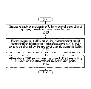
36.
[00172] In yet other implementations, a computer program including
instructions which, when executed by at least one processor, causes the at
least
one processor to carry out the functionality of the hyper cell 12 according to
any
of the embodiments described herein is provided. In yet other implementations,
a carrier containing the aforementioned computer program product is provided.
The carrier is one of an electronic signal, an optical signal, a radio signal,
or a
computer readable storage medium (e.g., a non-transitory computer readable
medium such as memory).
[00173] FIG. 9B illustrates an example TRP 1370. As shown in FIG. 9B,
the
TRP 1370 includes at least one processing unit 1450, at least one transmitter
Date Recue/Date Received 2021-01-22
84935225
33
1452, at least one receiver 1454, one or more antennas 1456, at least one
memory 1458, and one or more input/output devices or interfaces 1466. A
transceiver, not shown, may be used instead of the transmitter 1452 and
receiver 1454. A scheduler may be coupled to the processing unit 1450. The
scheduler may be included within or operated separately from the base station
1370. The processing unit 1450 implements various processing operations of the
base station 1370, such as signal coding, data processing, power control,
input/output processing, or any other functionality. The processing unit 1450
can
also be configured to implement some or all of the functionality and/or
embodiments described in more detail above. Each processing unit 1450 includes
any suitable processing or computing device configured to perform one or more
operations. Each processing unit 1450 could, for example, include a
microprocessor, nnicrocontroller, digital signal processor, field programmable
gate
array, or application specific integrated circuit.
[00174] Each transmitter 1452 includes any suitable structure for
generating
signals for wireless or wired transmission to one or more EDs or other
devices.
Each receiver 1454 includes any suitable structure for processing signals
received
wirelessly or by wire from one or more EDs or other devices. Although shown as
separate components, at least one transmitter 1452 and at least one receiver
1454 could be combined into a transceiver. Each antenna 1456 includes any
suitable structure for transmitting and/or receiving wireless or wired
signals.
Although a common antenna 1456 is shown here as being coupled to both the
transmitter 1452 and the receiver 1454, one or more antennas 1456 could be
coupled to the transmitter(s) 1452, and one or more separate antennas 1456
could be coupled to the receiver(s) 1454. Each memory 1458 includes any
suitable volatile and/or non-volatile storage and retrieval device(s) such as
those
described above in connection to the ED 110. The memory 1458 stores
instructions and data used, generated, or collected by the base station 1470.
For
example, the memory 1458 could store software instructions or modules
configured to implement some or all of the functionality and/or embodiments
described above and that are executed by the processing unit(s) 1450.
Date Recue/Date Received 2021-01-22
84935225
34
[00175] Each input/output device 1466 permits interaction with a user
or
other devices in the network. Each input/output device 1466 includes any
suitable structure for providing information to or receiving/providing
information
from a user, including network interface communications.
[00176] Figure 10 is a schematic block diagram of a wireless device 14
according to some embodiments of the present disclosure. As illustrated, the
wireless device 14 includes circuitry 18 configured to perform the wireless
device
functions described herein. In some implementations, the circuitry 18 includes
one or more processors 20 (e.g., Central Processing Units (CPUs), Application
Specific Integrated Circuits (ASICs), Field Programmable Gate Arrays (FPGAs),
and/or the like) and memory 22. The wireless device 14 also includes one or
more transceivers 24 each including one or more transmitter 26 and one or more
receivers 28 coupled to one or more antennas 30. In some other
implementations, the functionality of the wireless device 14 described herein
may
be fully or partially implemented in software or modules that is, e.g., stored
in
the memory 22 and executed by the processor(s) 20.
[00177] In some embodiments, the wireless device includes a
synchronization sequence detector 80 that performs synchronization sequence
detection as described herein. There is a characteristic determiner 82 that
makes
a determination of a characteristic of a source of a detected synchronization
sequence based on the detected sequence, for example high power or low power.
In some embodiments, there is a power controller 84 that adjusts transmit
power
based on the determined characteristic.
[00178] In yet other implementations, a computer program including
instructions which, when executed by at least one processor, causes the at
least
one processor to carry out the functionality of the wireless device 14
according to
any of the embodiments described herein is provided. In yet other
implementations, a carrier containing the aforementioned computer program
product is provided. The carrier is one of an electronic signal, an optical
signal, a
Date Recue/Date Received 2021-01-22
84935225
radio signal, or a computer readable storage medium (e.g., a non-transitory
computer readable medium such as memory).
[00179] Figures 11 to 26 are flowcharts of methods for execution in a
network or a UE. Note that any of the network methods can be combined, and
5 any of the modifications/alternatives described above can be applied to
these
methods. Similarly, any of the UE methods can be combined, any of the
modifications/alternatives described above can be applied to these methods.
[00180] Figure 11 is a flowchart of a method for execution by a
network
provided by an embodiment of the disclosure. The method begins at 1100 with
10 grouping each of a plurality of UEs to one of a plurality of groups,
based on one
or more factors. The method continues at 1102 with, for each group of UEs,
allocating a determined set of channel state information - reference symbol
(CSI-RS) ports to be shared by the group of user equipments (UEs). The method
continues at 1104 with at least one TRP serving each group of UEs transmitting
15 CSI-RS on the determined set of CSI-RS ports.
[00181] Figure 12 is a flowchart of a method for execution by TRPs of
a
hypercell provided by an embodiment of the disclosure. The method begins at
1200 with each TRP of the hypercell or part of a hypercell transmitting CSI-RS
on
at least one CSI-RS port assigned to the TRP. Optionally, the method continues
20 at 1202 with informing each UE of an initial set of CSI-RS ports from
which the
UE is to select a smaller number of high power ports to measure and report on.
Optionally, the method continues at 1204 with informing each UE of which CSI-
RS ports to measure.
[00182] Figure 13 is a flowchart of a method for execution by a
network
25 provided by an embodiment of the disclosure. The method begins at 1300
with
assigning a set of CSI-RS ports to a UE. The method continues at 1302 with at
least one TRP transmitting CSI-RS on the CSI-RS ports assigned to the UE.
Optionally, the method continues at 1304 with updating membership of the set
of
TRPs as a function of mobility of the UE.
Date Recue/Date Received 2021-01-22
84935225
36
[00183] Figure 14 is a flowchart of a method for execution by a
network
provided by an embodiment of the disclosure. The method begins with receiving
SRS symbols from a UE and performing uplink channel measurements based on
the received SRS symbols at 1400. The method continues at 1402 with allocating
a downlink zero power port. The method continues at 1404 with receiving a
measurement of interference and noise for the zero power port from the UE, and
at 1406 with determining a CQI based on the uplink channel measurements and
the measurement of interference and noise.
[00184] Figure 15 is a flowchart of a method for execution by a
network
provided by an embodiment of the disclosure. The method begins at 1500 with
assigning a respective SRS channel comprising a respective sequence, resource
element pattern, and time frequency location to each of a plurality of UEs for
SRS
transmission. The method continues at 1502 with, for each UE, associating the
SRS channel with a UE location encoded into a UE identifier.
[00185] Figure 16 is a flowchart of a method for execution by a network
provided by an embodiment of the disclosure. The method begins at 1600 with
assigning a respective SRS channel comprising a respective sequence, resource
element pattern, and time frequency location to each of a plurality of UEs for
SRS
transmission. The method continues at 1602 with, for each UE, associating the
SRS channel with a VTRP identifier of a VTRP serving a UE. Optionally, the
method continues at 1604 with assigning orthogonal sequences and/or
orthogonal patterns to UEs that are located in the same vicinity, or for UEs
that
are associated with a same VTRP.
[00186] Figure 17 is a flowchart of a method for execution by a
network
provided by an embodiment of the disclosure. The method begins at 1700 with a
TRP transmitting a demodulation reference symbol (DMRS) to a scheduled UE
comprising a sequence transmitted in a pattern of resource elements within a
location. The DMRSs transmitted to different UEs are orthogonal or have low
correlation and are assigned using a UE-based, location based, or VTRP based
approach, as indicated at 1702. Optionally, the method further comprises
Date Recue/Date Received 2021-01-22
84935225
37
informing the UE of DMRS ports used by co-paired UE for interference
cancellation purposes, at 1704.
[00187] Figure 18 is a flowchart of a method for execution by a UE
provided
by an embodiment of the disclosure. The method begins at 1800 with receiving a
VTRP identifier of a VTRP serving the UE. The method continues at 1802 with
determining a set of CSI-RS ports associated with the VTRP identifier, and at
1804 with measuring and reporting on the determined set of the CSI-RS ports.
Optionally, the method further involves determining the set of CSI-RS ports
comprises deriving the set from the VTRP identifier at 1806.
[00188] Figure 19 is a flowchart of a method for execution by a UE provided
by an embodiment of the disclosure. The method begins at 1900 with receiving a
UE identifier, the UE identifier including a field that encodes a location of
the UE.
The method continues at 1902 with determining a set of CSI-RS ports associated
with the location, and at 1904 with measuring and reporting on the determined
set of the CSI-RS ports.
[00189] Figure 20 is a flowchart of a method for execution by a UE
provided
by an embodiment of the disclosure. The method begins at 2000 with a UE
determining its own speed, and selecting a set of CSI-RS ports to measure and
report on based on the determined speed.
[00190] Figure 21 is a flowchart of a method for execution by a UE provided
by an embodiment of the disclosure. The method begins at 2100 with the UE
blindly detecting CSI-RS ports and measuring and reporting on a number of
highest-power ports.
[00191] Figure 22 is a flowchart of a method for execution by a UE
provided
by an embodiment of the disclosure. The method begins at 2200 with receiving
signaling defining an initial set of CSI-RS ports. The method continues at
2202
with the UE detecting an initial set of CSI-RS ports, and measuring and
reporting
back on some number of highest power ports within the set.
Date Recue/Date Received 2021-01-22
84935225
38
[00192] Figure 23 is a flowchart of a method for execution by a UE
provided
by an embodiment of the disclosure. The method begins at 2300 with the UE
determining an assigned SRS channel comprising a sequence, resource element
pattern, and time frequency location based on a location encoded into a UE
identifier. The method continues at 2302 with transmitting an SRS using the
assigned SRS channel.
[00193] Figure 24 is a flowchart of a method for execution by a UE
provided
by an embodiment of the disclosure. The method begins at 2400 with the UE
determining an assigned SRS channel comprising a sequence, resource element
pattern, and time frequency location based on a VTRP identifier of a VTRP
serving
the UE. The method continues at 2402 with transmitting an SRS using the
assigned SRS channel.
[00194] Figure 25 is a flowchart of a method for execution by a
network
provided by an embodiment of the disclosure. The method begins at 2500 with
transmitting a CSI-RS sequence using an NxK CSI-RS resource, the NxK CSI-RS
resource comprising N adjacent or non-adjacent OFDM symbols by K adjacent or
non-adjacent PRBs. Optionally, the NxK CSI-RS resource has repetitions of n
consecutive OFDM symbol x k consecutive PRB CSI-RS resource components,
wherein for each such CSI-RS resource component, the CSI-RS transmission
makes use of n1 out of the n OFDM symbols and makes use of k1 out of the k
PRBs, as indicated at 2502. Optionally, there is a separation between
consecutive CSI-RS resource components of a CSI-RS resource in the time
dimension and/or there is a separation between consecutive CSI-RS resource
components of the CSI-RS resource in the frequency dimension, as indicated at
2504. Optionally, each CSI-RS resource component is formed of s CSI-RS
resource component unit types, each CSI-RS resource component type having a
respective number v of adjacent PRBs in the frequency domain and a respective
number u of adjacent OFDM symbols in the time domain, as indicated at 2506.
Optionally, the method further involves mapping a CSI-RS sequence to a
plurality
of CSI-RS resource component units at 2508. Optionally, each CSI-RS sequence
is generated using at least one sequence seed as at 2510.
Date Recue/Date Received 2021-01-22
84935225
39
[00195] Figure 26 is a flowchart of a method for execution by a UE
provided
by an embodiment of the disclosure. The method begins at 2600 with receiving a
CSI-RS sequence using an NxK CSI-RS resource, the NxK CSI-RS resource
comprising N adjacent or non-adjacent OFDM symbols by K adjacent or non-
adjacent PRBs. Optionally, the NxK CSI-RS resource has repetitions of n
consecutive OFDM symbol x k consecutive PRB CSI-RS resource components,
wherein for each such CSI-RS resource component, the CSI-RS transmission
makes use of n1 out of the n OFDM symbols and makes use of k1 out of the k
PRBs, as indicated at 2602. Optionally, there is a separation between
consecutive CSI-RS resource components of a CSI-RS resource in the time
dimension and/or there is a separation between consecutive CSI-RS resource
components of the CSI-RS resource in the frequency dimension, as indicated at
2604. Optionally, each CSI-RS resource component is formed of s CSI-RS
resource component unit types, each CSI-RS resource component type having a
respective number v of adjacent PRBs in the frequency domain and a respective
number u of adjacent OFDM symbols in the time domain, as indicated at 2606.
Optionally, the method further involves mapping a CSI-RS sequence to a
plurality
of CSI-RS resource component units at 2608. Optionally, each CSI-RS sequence
is generated using at least one sequence seed as at 2610.
[00196] In an embodiment of the present disclosure, an apparatus is
provided. The apparatus includes means for receiving a CSI-RS sequence using
an NxK CSI-RS resource, the NxK CSI-RS resource comprising N adjacent or
non-adjacent OFDM symbols by K adjacent or non-adjacent PRBs, where N and K
are positive integers. In some embodiments, the apparatus may include other or
additional means for performing any one of or combination of steps described
in
the previous method embodiments. Further, any of the additional or alternative
embodiments or aspects of the method, as shown in any of the figures or
recited
in any of the claims, are also contemplated to include similar means.
[00197] In an embodiment of the present disclosure, an apparatus is
provided. The apparatus includes means for transmitting a CSI-RS sequence
using an NxK CSI-RS resource, the NxK CSI-RS resource comprising N adjacent
Date Recue/Date Received 2021-01-22
84935225
or non-adjacent OFDM symbols by K adjacent or non-adjacent PRBs, where N
and K are positive integers. In some embodiments, the apparatus may include
other or additional means for performing any one of or combination of steps
described in the previous method embodiments. Further, any of the additional
or
5 alternative embodiments or aspects of the method, as shown in any of the
figures or recited in any of the claims, are also contemplated to include
similar
means.
[00198] In an embodiment of the present disclosure, an apparatus is
provided. The apparatus includes any suitable means for performing any one of
10 -- or combination of steps described in the previous method embodiments.
Further,
any of the additional or alternative embodiments or aspects of the method, as
shown in any of the figures or recited in any of the claims, are also
contemplated
to include similar means.
[00199] In the preceding description, for purposes of explanation,
numerous
15 details are set forth in order to provide a thorough understanding of
the
embodiments. However, it will be apparent to one skilled in the art that these
specific details are not required. In other instances, well-known electrical
structures and circuits are shown in block diagram form in order not to
obscure
the understanding. For example, specific details are not provided as to
whether
20 the embodiments described herein are implemented as a software routine,
hardware circuit, firmware, or a combination thereof.
[00200] Embodiments of the disclosure can be represented as a computer
program product stored in a machine-readable medium (also referred to as a
computer-readable medium, a processor-readable medium, or a computer usable
25 medium having a computer-readable program code embodied therein). The
machine-readable medium can be any suitable tangible, non-transitory medium,
including magnetic, optical, or electrical storage medium including a
diskette,
compact disk read only memory (CD-ROM), memory device (volatile or non-
volatile), or similar storage mechanism. The machine-readable medium can
30 contain various sets of instructions, code sequences, configuration
information,
Date Recue/Date Received 2021-01-22
84935225
41
or other data, which, when executed, cause a processor to perform steps in a
method according to an embodiment of the disclosure. Those of ordinary skill
in
the art will appreciate that other instructions and operations necessary to
implement the described implementations can also be stored on the machine-
-- readable medium. The instructions stored on the machine-readable medium can
be executed by a processor or other suitable processing device, and can
interface
with circuitry to perform the described tasks.
[00201] The teachings of the present application may be embodied in
other
specific forms without departing from the subject matter of the claims. The
described example embodiments are to be considered in all respects as being
only illustrative and not restrictive. Selected features from one or more of
the
above-described embodiments may be combined to create alternative
embodiments not explicitly described, features suitable for such combinations
being understood within the scope of this disclosure.
[00202] The above-described embodiments are intended to be examples
only. Alterations, modifications and variations can be effected to the
particular
embodiments by those of skill in the art. The scope of the claims should not
be
limited by the particular embodiments set forth herein, but should be
construed
in a manner consistent with the specification as a whole.
Date Recue/Date Received 2021-01-22