Note: Descriptions are shown in the official language in which they were submitted.
CA 03024559 2018-11-09
WO 2017/218740 PCT/US2017/037624
METHOD OF MANUFACTURING A STRUCTURAL COMPONENT
CROSS-REFERENCE TO RELATED APPLICATIONS
[0001] This PCT International Patent Application claims the benefit of
U.S. Provisional
Patent Application Serial No. 62/350,402 filed June 15, 2016 entitled "Method
Of
Manufacturing A Structural Component," the entire disclosure of the
application being
considered part of the disclosure of this application and hereby incorporated
by reference.
BACKGROUND OF THE INVENTION
1. Field of the Invention
[0002] The invention relates generally to structural components for
automotive
vehicles, more particularly to door rings formed of steel, and methods of
manufacturing the
same.
2. Related Art
[0003] High strength structural components formed of steel for automotive
vehicles,
such as door rings or pillars, are designed with high strength to meet crash
standards set by the
automotive industry. Oftentimes, a reinforcement, also formed of a metal
material, is attached
to one of the pillars of the door ring to increase the strength in that area.
For example, as best
illustrated in Figure 1, according to the prior art processes, a reinforcement
portion 10 used to
form the reinforcement is first welded or otherwise attached to the door ring
blank 12 in
adjacent and overlaying with the pillar portion 14 for which it is intended to
reinforce. The
blank 12 including the reinforcement portion 10 attached to the pillar portion
14 is then heated
and hot stamped in a die together with one another. However, due to the
increased thickness in
the area where the pillar is reinforced and the air gaps present between the
reinforcement
portion 10 and the pillar portion 14 of the blank 12, this process requires a
long heating time
1
CA 03024559 2018-11-09
WO 2017/218740 PCT/US2017/037624
and long cooling time. In other words, the increased thickness in the area of
the reinforcement
area as well as the air gaps between the reinforcement and pillar portions 10,
14 of the blank 12
slows the cycle times, and thus reduces efficiency of the prior art process.
SUMMARY AND ADVANTAGES OF THE INVENTION
[0004] The invention provides a structural component, such as a door
ring, for an
automotive vehicle. The door ring includes a plurality of pillars and rails
surrounding at least
one door opening, for example an A-pillar and B-pillar, or a B-pillar and C-
pillar. The door
ring blank used to form the door ring includes a reinforcement portion which
extends through
the at least one door opening portion, and is then hot stamped in the same die
with the door ring
blank. In other words, the reinforcement portion is not welded or otherwise
attached to the
pillar portion of the door ring blank prior to hot stamping, but rather is a
separate part of the
blank which is separately formed into a reinforcement while forming the door
ring. In a
preferred arrangement, the reinforcement portion is located in a free space,
e.g., the door
opening portion of the door ring blank, during the hot stamping step in the
die. After hot
stamping, the formed reinforcement is removed from the formed door ring, and
then attached to
the door ring in a desired location of reinforcement, such as in overlaying
relationship with one
of the formed pillars.
[0005] The invention also provides a method of manufacturing a structural
component,
for example a door ring, for an automotive vehicle. The method includes
providing a door ring
blank, wherein the blank can include pillar portions and rail portions for use
in forming
respective portions of a door ring. The door ring blank also includes at least
one reinforcement
portion located in a free space, e.g., a door opening portion, disposed
between the pillar and rail
portions. The reinforcement portion is not attached to one of the pillar
portions, as in the prior
2
CA 03024559 2018-11-09
WO 2017/218740 PCT/US2017/037624
art processes, but rather is a separate part of the door ring blank. The
method proceeds by
heating the door ring blank, and disposing the heated blank in the die. The
method then
includes hot stamping the door ring blank, which includes the reinforcement
portion extending
through the at least one door opening portion, together in the die. After the
hot stamping step,
the reinforcement formed in the door opening is removed from the stamped door
ring, and then
attached to a desired location of the door ring, such as in overlaying
relationship with a
respective one of the pillars.
[0006] The method can be conducted with a reduced heating time, reduced
cooling
time, and overall reduced cycle time, due to the reduced thickness and lack of
air gaps between
the door ring blank and reinforcement portion. In other words, the
reinforcement portion does
not overlay the pillar portion for which it is intended to reinforce during
hot stamping, and thus
the efficiency of the process is improved.
BRIEF DESCRIPTION OF THE DRAWINGS
[0007] Other advantages of the present invention will be readily
appreciated, as the
same becomes better understood by reference to the following detailed
description when
considered in connection with the accompanying drawings wherein:
[0008] Figure 1 illustrates a prior art door ring blank including a
reinforcement portion
disposed in overlaying and attached relationship with a pillar portion;
[0009] Figure 2 illustrates a door ring blank including at least one
pillar portion, at least
one door opening portion, and at least one reinforcement portion extending
through the at least
door opening portion according to an aspect of the subject disclosure;
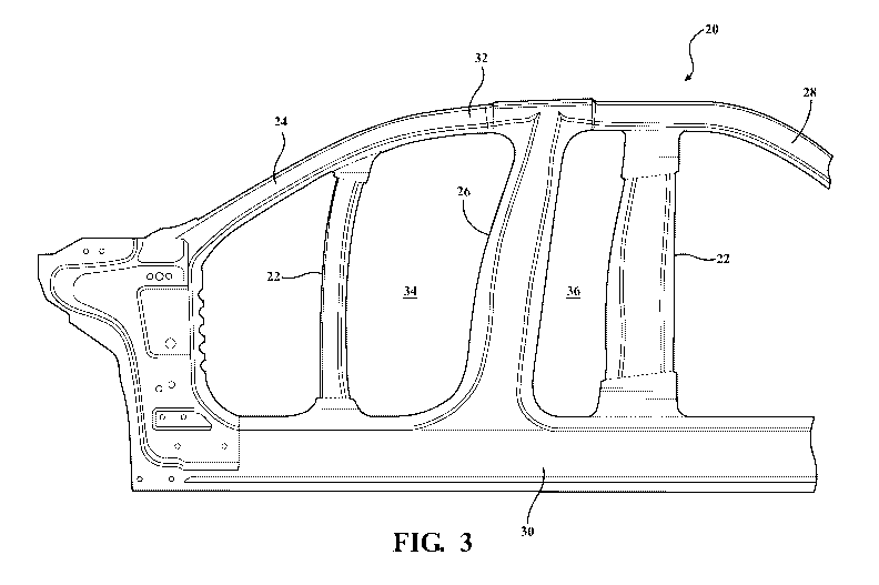
[00010] Figure 3 illustrates a door ring and at least one reinforcement
formed from the
door ring blank;
3
CA 03024559 2018-11-09
WO 2017/218740 PCT/US2017/037624
[00011] Figure 4 illustrates the reinforcement removed from the at least
one door
opening and attached to the at least one pillar of the door ring.
DESCRIPTION OF THE EXAMPLE EMBODIMENTS
[00012] With reference Figure 4, the invention ultimately provides a
structural
component, such as a door ring 20, for an automotive vehicle, which includes
at least one
reinforcement 22 to increase the strength of the door ring 20. As mentioned
previously, the
method used to manufacture the door ring 20 can be conducted with a reduced
heating time,
reduced cooling time, reduced overall cycle time, and improved efficiency,
compared to other
methods used to form door rings, such as by hot stamping the comparative door
ring blank 12
of Figure 1.
[00013] As best illustrated in Figure 4, the door ring 20 formed from the
subject method
preferably includes a plurality of pillars 24, 26, 28 and rails 30, 32
surrounding at least one
door opening 34, 36. For example, the door ring 20 can include an A-pillar 24,
an B-pillar 26,
and a lower rail 30 disposed around a front door opening 34, and a B-pillar
26, a C-pillar 28,
the lower rail 30, and an upper rail 32 disposed around a rear door opening
36. However, the
door ring 20 can include additional or fewer pillars, and other designs
besides the door ring
shown and formed in Figure 4.
[00014] The door ring 20 is comprised of metal, typically a steel
material. In the
example embodiment, the pillars 24, 26, 28, lower rail 30, and upper rail 32
are formed of a
boron-based medium carbon steel material. This material includes 5 weight
percent (wt. %) to
wt. % boron and 12 wt. % to 35 wt. % carbon, based on the total weight of the
material.
The material preferably has yield strength of 950 MPa to 1300 MPa, an
ultimately tensile
4
CA 03024559 2018-11-09
WO 2017/218740 PCT/US2017/037624
strength of 1350 MPa to 2000 MPa, and an elongation of greater than 5%. The
material of the
door ring 20 can be coated or uncoated.
[00015] As mentioned previously, the door ring 20 also includes at least
one
reinforcement 22 to increase the strength in certain areas of the door ring
20. The
reinforcement 22 can be attached to the door ring 20 in various different
locations. For
example, the reinforcement 20 can ultimately be aligned with and attached to
one of the pillars
24, 26, 28 of the door ring 20. In the example embodiment of Figure 4, the
door ring 20
includes multiple reinforcements 22, with a first reinforcement 22 attached to
the A-pillar 24
and a second reinforcement 22 attached to the B-pillar 26.
[00016] The reinforcements 22 are also formed of metal, typically the same
steel
material as the other components of the door ring 20. In the example
embodiment, the
reinforcements 22 are formed of a boron-based medium carbon steel material,
which is the
same material as the pillars 24, 26, 28 and rails 30, 32. This material
includes 5 weight percent
wt. % to 10 wt. % boron and 12 wt. % to 35 wt. % carbon, based on the total
weight of the
material. The material preferably has a yield strength of 950 MPa to 1300 MPa,
an ultimately
tensile strength of 1350 MPa to 2000 MPa, and an elongation of greater than
5%. The material
of the reinforcements 22 can also be coated or uncoated.
[00017] However, unlike the comparative door rings with reinforcements,
the
reinforcements 22 of the subject invention are not formed by first attaching
or welding them to
their respective pillars 24, 26 before hot stamping in the die. Rather, as
will be explained in
more detail below, the reinforcements 22 are formed from a separate part of
the blank used to
form the door ring 20 and hot stamped in the same die. For example, as best
illustrated in
Figure 2, during the hot stamping step, each reinforcement 22 is formed from a
reinforcement
CA 03024559 2018-11-09
WO 2017/218740 PCT/US2017/037624
portion 22' of a door ring blank 20' which is located in a free space between
two pillar portions
24', 26', 28', for example in one of the door opening portions 34', 36'. As
best illustrated in
sequential Figures 3-4, after the hot stamping step, the formed reinforcements
22 are separated
from the remainder of the door ring 20, and then attached to the formed door
ring 20 in the
desired location, such as in attached and aligned relationship with one of the
respective pillars
24, 26. The formed reinforcement 22 can be attached to the door ring 20 by
various different
methods, such as by spot welding, laser welding, metal insert gas (MIG)
welding, mechanical
lock, or another joining mechanism.
[00018] Another aspect of the subject disclosure provides a method of
manufacturing a
structural component for an automotive vehicle, for example the door ring 20
illustrated in
Figure 4. As best illustrated in Figure 2, the method first includes providing
a door ring blank
20' defining at least one door opening portion 34', 36'. The door ring blank
20' also includes
at least one reinforcement portion 22' extending through the at least one door
opening portion
34', 36'. In a preferred arrangement, the door ring blank 20' also includes an
A-pillar portion
24', a B-pillar portion 26', a C-pillar portion 28', a lower rail portion 30',
and an upper rail
portion 32'. The at least one door opening portion 34', 36' preferably
includes a front door
opening portion 34' collectively defined or bordered by the A-pillar portion
24', the B-pillar
portion 26', the lower rail portion 30', and the upper rail portion 32', as
well as a rear door
opening portion 36' collectively defined or bordered by the B-pillar portion
26', the upper rail
portion 32', the C-pillar portion 28', and the lower rail portion 30'. Each of
the portions of the
door ring blank 20' correspond with respective structural features ultimately
formed in the
resultant door ring 20 of Figure 4.
6
CA 03024559 2018-11-09
WO 2017/218740 PCT/US2017/037624
[00019] As further illustrated in Figure 2, in a preferred arrangement,
the door ring blank
20' can include multiple reinforcement portions 22' each extending through a
respective door
opening portion 34', 36'. For example, a first reinforcement portion 22' can
be disposed in the
front door opening portion 34' and extends from a top end attached to the A-
pillar portion 24'
to a bottom end attached to the lower rail portion 30' of the door ring blank
20'. Thus, the
majority of the first reinforcement portion 22' is disposed in the free space
of the front window
opening portion 34' during the ensuing hot stamping step. Also in this example
embodiment, a
second reinforcement portion 22' can be disposed in the rear door opening
portion 36' and
extends from a top end attached to the upper rail portion 32' to a bottom end
attached to the
lower rail portion 30' of the door ring blank 20'. Thus, the majority of the
second
reinforcement 22 is disposed in the free space of the rear window opening 26
during the
ensuing hot stamping step.
[00020] In an arrangement, the at least one reinforcement portion 22' can
be formed as a
separate component and then attached to the respective pillars or rails of the
door ring blank 20'
via spot welding, laser welding, metal insert gas (MIG) welding, mechanical
lock, or another
joining mechanism 38'. However, in another arrangement, the at least one
reinforcement
portion 20' can be formed or blanked as an integral part of the door ring
blank 20'. For
example, the door ring blank 20' including the at least one reinforcement
portion 20' can be
laser cut or stamped from a single sheet of metal.
[00021] Once the door ring blank 20' including the at least one
reinforcement portion
22' is formed, the method proceeds by heating the door ring blank 20', and
disposing the
heated door ring blank 20' in the stamping die. The method then proceeds by
hot stamping the
door ring blank 20' in the die to form the door ring 20 and the at least one
reinforcement 22
7
CA 03024559 2018-11-09
WO 2017/218740 PCT/US2017/037624
illustrated in Figure 3. During the hot stamping step, the at least one
reinforcement 22' is
located in a free space between the pillar and rail portions of the door ring
blank 20'. After the
hot stamping step, the method proceeds by removing the stamped door ring 20
and
reinforcement 22 from the stamping die, and transferring the formed components
to a separate
station for removing the at least one reinforcement 22, for example by laser
or in-die trimming,
from the door ring 20.
[00022] After removing the stamped reinforcements 22, and as best
illustrated in Figure
4, the method proceeds by attaching the at least one reinforcement 22 to the
door ring 20 in a
desired location. For example, the at least one reinforcement 22 can be
attached and aligned
with a respective one of the pillars 24, 26, 28. Various methods can be used
to attach the at
least one reinforcement 22 to the door ring 20. For example, the method can
include spot
welding, laser welding, metal insert gas (MIG) welding, mechanical lock, or
another joining
mechanism.
[00023] The method provides numerous advantages over the comparative
process. For
example, the door ring blank 20' has a reduced thickness as compared to the
prior art door ring
blank 10 of Figure 1, since the reinforcement portion 22' is not aligned with
and overlaying
either of the pillar portions 24', 26', and thus the heating and cooling times
during the heating
and stamping steps are reduced. In addition, there are no air gaps between the
reinforcement
portion 22' and the respective pillar portions 24', 26', 28' as are present in
the comparative
process. The lack of air gaps also reduces heating and cooling time. Thus, the
overall cycle
time and efficiency of the method of manufacturing the door ring 20 from a
door ring blank 20'
which includes a reinforcement portion 22' extending through a door opening
portion 34', 36'
improves over the prior art processes.
8
CA 03024559 2018-11-09
WO 2017/218740 PCT/US2017/037624
[00024] Many modifications and variations of the present disclosure are
possible in light
of the above teachings and may be practiced otherwise than as specifically
described while
within the scope of the invention. Thus, the foregoing description of the
embodiments has been
provided for purposes of illustration and description. It is not intended to
be exhaustive or to
limit the disclosure. Individual elements or features of a particular
embodiment are generally
not limited to that particular embodiment, but, where applicable, are
interchangeable and can be
used in a selected embodiment, even if not specifically shown or described.
The same may also
be varied in many ways. Such variations are not to be regarded as a departure
from the
disclosure, and all such modifications are intended to be included within the
scope of the
disclosure.
9