Note: Descriptions are shown in the official language in which they were submitted.
A CINCHING CORD FOR IMPLANTATION INTO A CARDIAC VALVE ANNULUS
BACKGROUND
[0001] Our prior applications WO 2013/088327 and WO 2014/195786,
describe affixing a cinching cord to an annulus of a cardiac
valve, and attaching a closed loop or ring to an annulus of a cardiac valve.
SUMMARY OF THE INVENTION
[0002] This application describes alternative approaches for cinching
the annulus of a
cardiac valve, for cinching other types of anatomic passages, and for
preventing expansion of
an anatomic annulus. In the cinching embodiments, the cinching cord is
incorporated into an
implant, and the implant is implanted into the annulus or passage or into
adjacent tissue.
After the implant with the cinching cord has been implanted, it becomes
possible to reduce
the diameter of the annulus by cinching the cinching cord. In the closed loop
embodiments,
the closed loop of cord is incorporated into an implant, and the implant is
implanted into an
anatomic annulus or into adjacent tissue (e.g., into a cardiac valve annulus
or into the leaflets
of a cardiac valve near the base of those leaflets).
[0003] One aspect of the invention is directed to an apparatus for
cinching an annulus
of a cardiac valve. The annulus has an initial circumference. This apparatus
includes at least
four anchors. Each of the anchors has a pointy distal end and a proximal end,
and each of the
anchors has a slot that runs in a proximal-to-distal direction. Each of the
anchors is
configured for implantation into tissue in a distal direction and is also
configured to resist
extraction from the tissue in a proximal direction subsequent to implantation.
[0004] This apparatus also includes at least four sliding members.
Each of the sliding
members is disposed in a slot of a respective one of the anchors, with a first
portion of the
- 1 -
CA 3024628 2019-02-05
CA 03024628 2018-11-16
WO 2017/204848
PCT/US2016/060948
sliding member extending out of the slot in a first direction and a second
portion of the
sliding member extending out of the slot in a second direction. The sliding
member and the
slot are configured so that the anchor can slide in a distal direction with
respect to the sliding
member. Each of the sliding members has at least one protrusion on the first
portion of the
sliding member configured to prevent the sliding member from passing through
the slot in the
second direction. The second portion of each of the sliding members has an
aperture.
[0005] This apparatus also includes a cinching cord having a distal loop
portion, the
distal loop portion having a first end region a second end region. The
cinching cord has a
first proximal portion connected to the first end region and a second proximal
portion
connected to the second end region and the distal loop portion of the cinching
cord passes
through the aperture in each of the sliding members. Each of the apertures
retains the distal
loop portion of the cinching cord within the aperture such that the presence
of the distal loop
portion of the cinching cord in the aperture prevents the sliding member from
passing through
the slot in the first direction. The anchors and sliding members are
distributed around the
distal loop portion of the cinching cord at positions configured to facilitate
implantation of
the anchors into the annulus or into leaflets of the cardiac valve adjacent to
the annulus with
the first end region positioned next to the second end region, so that
subsequent to
implantation, pulling both the first proximal portion and the second proximal
portion in a
proximal direction while the first end region is held next to the second end
region will reduce
the circumference of the annulus.
[0006] Optionally, this apparatus further includes a continuous sleeve of
material that
is disposed over the distal loop portion of the cinching cord and passes
through the aperture
in each of the sliding members, and the continuous sleeve of material accepts
tissue ingrowth.
- 2 -
CA 03024628 2018-11-16
WO 2017/204848
PCT/US2016/060948
[0007] Optionally, this apparatus further includes at least one sleeve of
material
disposed over the distal loop portion of the cinching cord, and the least one
sleeve of material
accepts tissue ingrowth. The at least one sleeve of material may optionally be
lined with a
material that resists tissue ingrowth.
[0008] Optionally, the distal loop portion of the cinching cord is coated
with a
material that resists tissue ingrowth.
[0009] Optionally, each of the anchors comprises at least one barb
configured to resist
extraction of the anchor from the tissue. Each of the anchors may include a
first panel having
a cylindrical curve on a first side of the slot and a second panel having a
cylindrical curve
disposed on a second side of the slot.
[0010] Optionally, the at least four anchors comprises at least eight
anchors and the at
least four sliding members comprises at least eight sliding members.
[0011] Optionally, the at least four anchors comprises at least 16 anchors
and the at
least four sliding members comprises at least 16 sliding members.
[0012] Optionally, the sliding member comprises a thin sheet of metal, and
the
protrusion is T-shaped.
[0013] Optionally, this apparatus further includes a continuous sleeve of
material that
is disposed over the distal loop portion of the cinching cord and passes
through the apertures
in each of the sliding members, and the continuous sleeve of material accepts
tissue ingrowth.
The cinching cord is coated with a material that resists tissue ingrowth. Each
of the anchors
comprises at least one barb configured to resist extraction of the anchor from
the tissue, and
each of the anchors comprises a first panel having a cylindrical curve on a
first side of the slot
and a second panel having a cylindrical curve disposed on a second side of the
slot. The at
- 3 -
CA 03024628 2018-11-16
WO 2017/204848
PCT/US2016/060948
least four anchors comprises at least eight anchors, and the at least four
sliding members
comprises at least eight sliding members.
[0014] A second aspect of the invention is directed to an apparatus for
cinching an
anatomic passage that has an initial circumference. This apparatus includes at
least four
anchors. Each of the anchors has a pointy distal end and a proximal end, and
each of the
anchors has a slot that runs in a proximal-to-distal direction. Each of the
anchors is
configured for implantation into tissue in a distal direction and is also
configured to resist
extraction from the tissue in a proximal direction subsequent to implantation
[0015] This apparatus also includes at least four sliding members. Each of
the sliding
members is disposed in a slot of a respective one of the anchors, with a first
portion of the
sliding member extending out of the slot in a first direction and a second
portion of the
sliding member extending out of the slot in a second direction. The sliding
member and the
slot are configured so that the anchor can slide in a distal direction with
respect to the sliding
member. Each of the sliding members has at least one protrusion on the first
portion of the
sliding member configured to prevent the sliding member from passing through
the slot in the
second direction. The second portion of each of the sliding members has an
aperture;
[0016] This apparatus also includes a cinching cord having a distal loop
portion. The
distal loop portion has a first end region a second end region, and the
cinching cord has a first
proximal portion connected to the first end region and a second proximal
portion connected
to the second end region. The distal loop portion of the cinching cord passes
through the
aperture in each of the sliding members
[0017] This apparatus also includes at least one sleeve of material
disposed over the
distal loop portion of the cinching cord, wherein the least one sleeve of
material accepts
tissue ingrowth. Each of the apertures retains the distal loop portion of the
cinching cord
- 4 -
CA 03024628 2018-11-16
WO 2017/204848
PCT/US2016/060948
within the aperture such that the presence of the distal loop portion of the
cinching cord in the
aperture prevents the sliding member from passing through the slot in the
first direction,
[0018] The anchors and sliding members are distributed around the distal
loop portion
of the cinching cord at positions configured to facilitate implantation of the
anchors into the
anatomic passage or into tissue adjacent to the anatomic passage with the
first end region
positioned next to the second end region, so that subsequent to implantation,
pulling both the
first proximal portion and the second proximal portion in a proximal direction
while the first
end region is held next to the second end region will reduce the circumference
of the
anatomic passage.
[0019] Optionally, the at least one sleeve of material comprises a
continuous sleeve of
material that is disposed over the distal loop portion of the cinching cord
and passes through
the aperture in each of the sliding members.
[0020] Optionally, the at least one sleeve of material is lined with a
material that
resists tissue ingrowth.
[0021] Optionally, the distal loop portion of the cinching cord is coated
with a
material that resists tissue ingrowth.
[0022] Optionally, the at least four anchors comprises at least eight
anchors and the at
least four sliding members comprises at least eight sliding members.
[0023] A third aspect of the invention is directed to an apparatus for
preventing
expansion of an anatomic annulus. This apparatus includes at least four
anchors. Each of the
anchors has a pointy distal end and a proximal end, and each of the anchors
has a slot that
runs in a proximal-to-distal direction. Each of the anchors is configured for
implantation into
- 5 -
CA 03024628 2018-11-16
WO 2017/204848
PCT/US2016/060948
tissue in a distal direction and is also configured to resist extraction from
the tissue in a
proximal direction subsequent to implantation.
[0024] This apparatus also includes at least four sliding members. Each of
the sliding
members is disposed in a slot of a respective one of the anchors, with a first
portion of the
sliding member extending out of the slot in a first direction and a second
portion of the
sliding member extending out of the slot in a second direction. The sliding
member and the
slot are configured so that the anchor can slide in a distal direction with
respect to the sliding
member, and each of the sliding members has at least one protrusion on the
first portion of
the sliding member configured to prevent the sliding member from passing
through the slot in
the second direction. The second portion of each of the sliding members has an
aperture.
[0025] This apparatus also includes a closed loop of cord that passes
through the
aperture in each of the sliding members.
[0026] Each of the apertures retains the cord within the aperture such that
the
presence of the cord in the aperture prevents the sliding member from passing
through the
slot in the first direction. The anchors and sliding members are distributed
around the closed
loop of cord at positions configured to facilitate implantation of the anchors
into the anatomic
annulus or into tissue adjacent to the anatomic annulus, so that subsequent to
implantation,
the closed loop of cord prevents the anatomic annulus from expanding.
[0027] Optionally, the anatomic annulus is a cardiac valve annulus and the
tissue
adjacent to the anatomic annulus comprises leaflets of the cardiac valve.
[0028] Optionally, this apparatus further includes a continuous sleeve of
material that
is disposed over the closed loop of cord and passes through the aperture in
each of the sliding
members, and the continuous sleeve of material accepts tissue ingrowth.
- 6 -
CA 03024628 2018-11-16
WO 2017/204848
PCT/US2016/060948
[0029] Optionally, this apparatus further includes at least one sleeve of
material
disposed over the closed loop of cord, and the least one sleeve of material
accepts tissue
ingrowth.
[0030] Optionally, each of the anchors comprises at least one barb
configured to resist
extraction of the anchor from the tissue.
[0031] Optionally, the at least four anchors comprises at least eight
anchors and the at
least four sliding members comprises at least eight sliding members.
BRIEF DESCRIPTION OF THE DRAWINGS
[0032] FIG. 1 depicts a first embodiment of a cinching implant for
implantation into
an annulus of a cardiac valve.
[0033] FIG. 2A depicts a second embodiment of a cinching implant for
implantation
into an annulus of a cardiac valve.
[0034] FIG. 2B is a detail of the FIG. 2A embodiment.
[0035] FIG. 3 is a detail of the anchors that are used in the FIG. 1 and 2A
embodiments.
[0036] HG. 4A shows the relationship between the anchor and the sliding
member
prior to deployment.
[0037] HG. 4B shows the relationship between those components after the
anchor has
been driven distally by the launcher.
[0038] HG. 5A shows a launcher that may be used to drive a respective
anchor into
the tissue, prior to launching of the anchor.
- 7 -
CA 03024628 2018-11-16
WO 2017/204848
PCT/US2016/060948
[0039] FIG. 5B shows a launcher of FIG. 5A after the anchor has been
launched.
[0040] FIG. 6A depicts a catheter-based device for delivering the cinching
implant to
the vicinity of the target annulus.
[0041] FIG. 6B is a detailed view of the interface between the sliding
member and the
sleeve that surrounds the distal loop portion of the cinching cord before the
launcher has been
actuated.
[0042] FIG. 6C is a detail view of that interface as the anchor is exiting
the body of
the launcher.
[0043] FIG. 7 shows how cinching of the cinching cord may be implemented
using a
push-tube.
[0044] FIG. 8A depicts an alternative approach for connecting the anchors
to an
implant.
[0045] FIG. 8B is a detail of the FIG. 8A implant.
[0046] FIG. 9 depicts an embodiment of an apparatus for preventing
expansion of an
anatomic annulus such as a cardiac valve annulus.
DESCRIPTION OF THE PREFERRED EMBODIMENTS
[0047] FIG. 1 depicts a cinching implant 30 that is designed for
implantation into an
annulus of a cardiac valve such as the mitral valve annulus. The cinching
implant 30 may be
implanted either directly into the annulus itself, or into the leaflets of the
cardiac valve near
the base of those leaflets. For example, when the implant is installed in the
mitral valve, it
may be installed directly into the mitral annulus via a catheter from the
atrium side or into the
leaflets via a catheter from the ventricle side. Note that these two
alternative approaches for
- 8 -
CA 03024628 2018-11-16
WO 2017/204848
PCT/US2016/060948
affixing implants to either the annulus the leaflets are described in
application WO
2014/195786 (in connection with an implant that has a different construction).
[0048] The cinching implant 30 includes a cinching cord that has a distal
loop portion
33. The distal loop portion has a first and region 33a and a second end region
33b. The first
end region is connected to a first proximal portion 31 of the cinching cord,
and the second
end region is connected to a second proximal portion 32 of the cinching cord.
Most
preferably, all three portions 31, 32, 33 are formed from a single continuous
cord, in which
case the connections between the various regions are an inherent property of
the single
continuous cord. Note that as used herein, the term "cord" includes
monofilament cords,
multi-filament cords, braided cords, wires, and other cord-shaped flexible
structures.
Suitable materials for the cinching cord include stainless steel, Dyneema,
ultra high
molecular weight polyethylene, LCP, Nylon, PET, Dacron, and other high-
strength polymers,
all of which are biocompatible and sufficiently strong to withstand cinching.
The diameter of
the cord is preferably between 0.2 and 0.8 mm. The length of the distal loop
portion 33
matches the diameter of the annulus to which the implant will be attached. In
some
embodiments, cinching is implemented from outside the patient's body via a
catheter, in
which case the first and second proximal portions 31, 32 are sufficiently long
(e.g., 25-100
cm each) to reach from the annulus to outside the patient's body via the
patient's vasculature.
[0049] In alternative embodiments (not shown), instead of forming all three
portions
31, 32, 33 from a single continuous cord, each of those portions may be
implemented using
three separate pieces of cord that are joined together (e.g. using welding,
clips, knots, bonds,
or alternative connecting approaches) so as to form a composite cinching cord.
[0050] The FIG. 2A embodiment is similar to the FIG. 1 embodiment, but adds
an
additional component. More specifically, in the FIG. 2A embodiment, the distal
loop portion
- 9 -
CA 03024628 2018-11-16
WO 2017/204848
PCT/US2016/060948
33 is surrounded by a sleeve 36. (Because it is surrounded by the sleeve 36,
the distal loop
portion 33 is not visible in FIG. 2A.) The sleeve 36 is made from a material
that accepts
tissue ingrowth, such as PET braid, Nylon braid, wool, silk, or non-woven
polymers. As a
result, after the implant 30 is implanted into the annulus, tissue that comes
into contact with
the implant 30 will slowly ingrow into the sleeve 36. After the tissue
ingrowth process has
continued for a sufficient amount of time (e.g., 1-3 months after
implantation), the implant
will be affixed to the annulus with an extremely strong connection that will
be able to
withstand cinching. In the embodiment depicted in FIG. 2A, the sleeve 36 is
continuous and
tubular, and runs the entire length of the distal loop portion 33. In
alternative embodiments
(not shown), two or more separate pieces of sleeving may be used instead of a
continuous
sleeve. For example, in a system having N anchors 40, a separate piece of
tubular sleeving
may be positioned between each of the N anchors 40, in which case N-1 separate
pieces of
sleeving would be used. In alternative embodiments, non-tubular sleeving may
be used.
[0051] The distal loop portion 33 is also coated with a coating 34 that
resists tissue
ingrowth. The coating 34 on the distal loop portion 33 prevents the tissue
that grows into the
implant from adhering to the distal loop portion 33, so that the distal loop
portion 33 will be
able to slide freely within the sleeve 36 when cinching is eventually
implemented, and
prevent the distal loop portion 33 from becoming a locked in place by the
surrounding tissue
due to ingrowth. Suitable materials for the coating 34 include Teflon and ePT1-
E.
[0052] In alternative embodiments, the coating 34 is omitted, and it is
replaced by a
lining on the interior surface of the sleeve 36 (not shown) that resists
tissue ingrowth. This
ingrowth-preventing lining helps the distal loop portion 33 slide freely
within the sleeve 36
when cinching is eventually implemented, and helps prevent the distal loop
portion 33 from
becoming locked in place by the surrounding tissue due to tissue ingrowth.
Suitable materials
- 10 -
CA 03024628 2018-11-16
WO 2017/204848
PCT/US2016/060948
for the ingrowth ¨ preventing lining on the interior surface of the sleeve 36
include Teflon
and ePTFE.
[0053] In other alternative embodiments, e.g., when the surface of the
distal loop
portion 33 resists ingrowth sufficiently without help from a coating or
lining, both the coating
and the lining may be omitted.
[0054] The implant 30 includes at least four anchors 40 and sliding members
50 that
are distributed around the distal loop portion 33 of the cinching cord at
positions configured
to facilitate implantation of the anchors 40 into the annulus (or into
leaflets of the cardiac
valve adjacent to the annulus) with the first end region of the distal loop
portion 33 positioned
next to the second end region of the distal loop portion 33. Suitable
materials for the anchors
40 and the sliding members 50 include biocompatible metals (e.g., stainless
steel) and rigid
plastics or composites that are biocompatible. Subsequent to implantation (and
preferably
after tissue ingrowth occurs), pulling both the first proximal portion 31 and
the second
proximal portion 32 in a proximal direction while the first end region is held
next to the
second end region will reduce the circumference of the annulus into which the
implant has
been implanted.
[0055] The embodiments illustrated in FIGS. 1 and 2A each have eight
anchors 40
and eight corresponding sliding members 50. But in alternative embodiments, a
different
number of anchors 40 may be used. In some preferred embodiments, a larger
number of
miniature anchors are used. For example, 20 anchors that are between 4 and 8
mm long may
be used. In other alternative embodiments, 16 or more anchors are used (e.g.,
between 16
and 24); and in other alternative embodiments, 8 or more anchors are used. In
the latter case,
the anchors may be larger (e.g., between 6 and 12 mm long). It is expected
that a minimum of
four anchors is required to effectively affix the implant 30 onto the annulus.
-11-
CA 03024628 2018-11-16
WO 2017/204848
PCT/US2016/060948
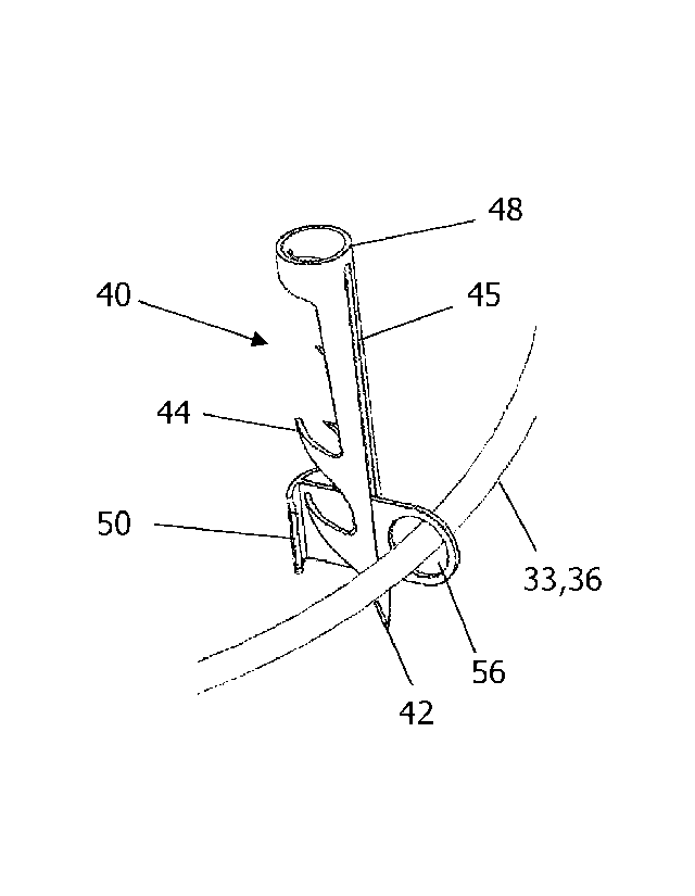
[0056] FIG. 3 is a detail of the anchors 40 and sliding members 50 that are
used in the
FIG. 1 and 2A embodiments. Each of the anchors 40 has a pointy distal end 42
and a
proximal end 48, and each of the anchors 40 has a slot 45 that runs in a
proximal-to-distal
direction. Each of the anchors 40 is configured for implantation into tissue
(e.g., the annulus
or the base of the leaflets) in a distal direction and is also configured to
resist extraction from
the tissue in a proximal direction subsequent to implantation. In these
embodiments, the
pointy distal end 42 helps the anchor 40 pierce the tissue when the anchor 40
is launched into
the tissue by an anchor-launcher, and a plurality of barbs 44 serve to resist
extraction of the
anchor 40 from the tissue in a proximal direction subsequent to implantation.
Although the
anchors illustrated in FIG. 3 have four barbs 44, a different number of barbs
(e.g., between
one and six) may be used in alternative embodiments.
[0057] The implant 30 also includes at least four sliding members 50, and
each of the
sliding members 50 is disposed in a slot 45 of a respective one of the anchors
40, with a first
portion 51 of the sliding member 50 extending out of the slot 45 in a first
direction and a
second portion 52 of the sliding member 50 extending out of the slot 45 in a
second direction.
The sliding member 50 and the slot 45 are configured so that the anchor 40 can
slide in a
distal direction with respect to the sliding member 50. Each of the sliding
members 50 has at
least one protrusion 54 on the first portion 51 of the sliding member 50, and
this protrusion
54 is configured to prevent the sliding member 50 from passing through the
slot 45 in the
second direction. In the FIG. 3 embodiment, the protrusion 54 is T-shaped, but
alternative
shapes for the protrusion may also be used.
[0058] The second portion 52 of each of the sliding members 50 has an
aperture 56.
The first portion 51 and second portion 52 of the sliding member 50 may be
formed from a
- 12 -
CA 03024628 2018-11-16
WO 2017/204848
PCT/US2016/060948
thin sheet of metal, in which case the aperture 56 would be a hole through
that thin sheet of
metal.
[0059] Returning now to FIGS. 1 and 2A, the distal loop portion 33 of the
cinching
cord passes through the aperture 56 in each of the sliding members 50, and
each of the
apertures 56 is configured to retain the distal loop portion 33 of the
cinching cord within the
aperture 56. In addition, in the FIG. 2A embodiment (which has a continuous
sleeve 36
disposed over the distal loop portion 33), the sleeve 36 also passes through
the aperture 56 in
each of the sliding members 50. In alternative embodiments that use separate
sections of
sleeve between each anchor, the sleeve would not pass through the aperture 56.
[0060] The presence of the distal loop portion 33 of the cinching cord in
the aperture
56 prevents the sliding member 50 from passing through the slot 45 in the
first direction. In
the context of the FIGS. 1 and 2A embodiment, this means that the presence of
the distal loop
portion 33 of the cinching cord in the aperture 56 in each of the sliding
members 50 prevents
the sliding members 50 from passing through the slot 45 in a radially inward
direction (i.e.
towards the center of the loop). In addition, the at least one protrusion 54
on each of the
sliding members 50 in this context prevents the respective sliding member 50
from passing
through the slot 45 in a radially outward direction.
[0061] Note that in some embodiments, when the size of the aperture 56
matches the
size of the sleeve 36 exactly, no portion of the aperture 56 will be able to
extend through the
slot 45 in the anchor 40, which would mean that the aperture 56 is limited
entirely to the first
portion 51 of the sliding member 50.
[0062] In alternative embodiments, when the size of the aperture 56 is
larger than the
sleeve 36, a portion of the aperture 56 may be able to slip through the slot
45, which would
mean that the aperture 56 extends into the second portion 52 of the sliding
member 50 (i.e.,
- 13 -
CA 03024628 2018-11-16
WO 2017/204848
PCT/US2016/060948
the portion of the sliding member 50 on the other slide of the slot 45). This
is not problematic
because the distal loop portion 33 of the cinching cord (and the sleeve 36)
will not be able to
pass through the slot 45 in the first direction, so they will always stay on
the side of the
aperture 56 that corresponds to the first portion 51 of the sliding member 50.
[0063] In other alternative embodiments (not shown), the sliding member may
be
formed from a U-shaped member having two arms and a base, and an end of each
arm of the
U-shaped member is connected to an end cap that protrudes sufficiently to
prevent the sliding
member from passing through the slot 45 in the second direction. In this
situation, the
aperture would extend all the way from the base of the U-shaped member to the
end cap.
[0064] FIGS. 4A and 4B show the relationship between the anchor 40, the
slot 45 in
the anchor 40, and the sliding member 50 at various stages of deployment.
Prior to
deployment, the body of the anchor 40 will be disposed on the proximal side of
the cinching
cord 33 (and the optional sleeve 36), as seen in FIG. 4A. The sliding member
50 passes
through the slot 45 in the anchor 40 at the distal end of the slot 45, and the
cinching cord 33
passes through the aperture 56 of the sliding member 50. Prior to deployment,
the cinching
implant 30 is positioned up against the tissue into which it will be
implanted, with the pointy
distal ends 42 of the anchors facing the tissue.
[0065] During deployment, a launcher 60 (discussed below in connection with
FIGS.
5A and 5B) drives the anchor 40 in a distal direction. When this occurs, the
anchor 40 will
slide distally with respect to the sliding member 50 due to the sliding
interface between the
anchor 40 and the sliding member 50 at the slot 45. The pointy distal end 42
of the anchor 40
will be driven into the tissue and the barbs 44 will become embedded into the
tissue.
[0066] FIG. 4B shows the relationship between these same components after
the
anchor 40 has been driven distally by the launcher. More specifically, the
anchor 40 will have
- 14 -
CA 03024628 2018-11-16
WO 2017/204848
PCT/US2016/060948
moved distally with respect to the sliding member 50, such that the sliding
member 50 is
disposed at the proximal end of the slot 45 of the anchor 40. In this
position, the pointy distal
end 42 and the barbs 44 of the anchor 45 will he disposed on the distal side
of the cinching
cord 33 (and the optional sleeve 36), as seen in FIG. 4B. Because the cinching
implant 30
was positioned up against the tissue prior to deployment when the anchors 40
were driven
into the tissue, the barbs 44 of the anchors 40 will be embedded in the
tissue, which will affix
the cinching implant 30 to the tissue.
[0067] In some preferred embodiments, the portion of the anchor 40 on
either side of
the slot 45 has a cylindrical curve, and in some preferred embodiments, the
proximal head
portion 48 of the anchor 40 is ring-shaped. In some preferred embodiments, the
anchor
measures between 4 mm and 7 mm from the distal and of the tip 42 to the
proximal end of the
head portion 48, and the ring shaped head portion 48 has a diameter between
0.5 mm and 2
mm, and the brackets and launcher are sized to fit the dimensions of the
anchor 40.
[0068] FIGS. 5A and 5B show an example of a launcher 60 that may be used to
drive
a respective anchor 40 into the tissue, and these figures show the
relationship between the
launcher 60, the anchor 40, and the bracket 50. More specifically, FIG. 5A
depicts those
three components immediately prior to launching of the anchors, and FIG. 5B
depicts those
three components immediately after launching of the anchors. Note that each
anchor 40 of the
implant has its own individual launcher 60.
[0069] Beginning with FIG. 5A, the launchers 60 includes a launcher body 62
with a
trigger slot 63 located about midway down the launcher body 62, and a distal
slot 64 located
at the distal end of the launcher body 62. The launcher body 62 is preferably
cylindrical. A
compressed spring 68 is disposed in the proximal end of the launcher 60, and
the anchor 40 is
disposed in the distal and of the launcher 60 immediately beneath the
compressed spring 68,
- 15 -
so that the distal end of the compressed spring 68 pushes on the head portion
48 of the anchor
40. (The head portion 48 of the anchor is at the proximal end of the anchor
40). A pull wire
66 extends down through the center of the compressed spring 68, and the distal
and 67 of the
pull wire 66 extends out through the trigger slot 63. In this embodiment, the
distal end 67 of
the pull wire passes below the head portion 48 of the anchor just before the
distal end 67 of
the pull wire exits the trigger slot 63. Due to this configuration, as long as
the distal end 67 of
the pull wire sticks out through the trigger slot 63, the pull wire prevents
the spring 68 from
expanding. At this stage, the relationship between the anchor 40 arid the
sliding member 50
is at the same as shown in FIG. 4A.
[0070] The launcher 60 is triggered by pulling on the pull wire 66 in
a proximal
direction. In some embodiments, the triggering action works best when the pull
wire 66 is
pulled using a quick pulling action (e.g. by jerking the proximal end of the
wire rapidly in a
proximal direction). An example of a suitable apparatus for implementing this
quick pulling
action is disclosed in WO 2014/195786 A2.
[0071] Pulling on the proximal end of the pull wire 66 causes the
distal and 67 of the
pull wire 66 to be withdrawn from the trigger slot 63. As soon as this occurs,
the spring 68
will begin to expand. The proximal end of the spring 68 is held in position by
the spring
retainer 69, so the distal end of the spring 68 will move in a distal
direction when the spring
68 expands. The expanding spring 68 will push the proximal head portion 48 of
the anchor
40 in a distal direction, which will drive the anchor 40 into the tissue.
During this stage of
launching, the anchor 40 slides with respect to the bracket 50 as explained
above in
connection with FIGS. 4A and 4B. The distal end of the anchor will start
sliding out of distal
end of the launcher body 62. The pointy distal end 42 of the anchor 40 will
pierce the tissue,
and the anchor 40 will continue moving in a distal direction until the
proximal head portion
- 16 -
CA 3024628 2019-02-05
CA 03024628 2018-11-16
WO 2017/204848
PCT/US2016/060948
48 of the anchor encounters the sliding member 50. When this happens, the
expanding spring
68 will begin to push both the anchor 40 and the sliding member 50 in a distal
direction until
both the anchor 40 and the sliding member 50 have been ejected out from the
distal end of the
launcher body 62, as seen in FIG. 5B. (Note that the bracket 50 remains
captive within the
slot 45, as explained above in connection with FIGS. 4A and 4B.) At this
point, the anchor
40 will be embedded in the tissue. The barbs on the anchors 40 are configured
to prevent the
anchors from pulling out of the tissue in a proximal direction.
[0072] FIG. 6A a depicts a catheter-based device 70 for delivering the
cinching
implant 30 to the vicinity of the target valve annulus so that it can be
implanted into that
annulus (or into the base of the leaflets). This device has one launcher 60
for each anchor
that appears on the cinching implant 30. Each launcher 60 is supported by one
of the pre-
formed arms 72. The cinching implant 30 and the pre-formed arms 72 are
collapsible so that
they can be delivered through the shaft 75 of the catheter-based device 70,
but those
components are depicted in FIG 6A after having been extended out past the
distal end of the
catheter. The first proximal portion 31 of the cinching cord, and the second
proximal portion
32 of the cinching cord also run through the shaft 75, as do the pull wires
(66, shown in FIG.
5A) that are used to trigger the launchers 60. The cinching implant 30 is
maneuvered into
position on the annulus, and the triggers of the launchers 60 are actuated.
[0073] The interface between the launcher 60 and the cinching implant 30 is
shown in
the FIGS. 6B and 6C detailed views, which show the interface described above
between the
sliding member 50 and the sleeve 36 that surrounds the distal loop portion 33
of the cinching
cord. More specifically, FIG. 6B depicts that interface before the launcher 60
has been
actuated; and FIG. 6C depicts that interface as the anchor 40 is exiting the
launcher body 62
of the launcher 60. After being launched, the anchors 40 will become embedded
in the
- 17 -
CA 03024628 2018-11-16
WO 2017/204848
PCT/US2016/060948
annulus (or into the leaflets), and both the anchors 40 and the sliding
members 50 will be
ejected from the launcher body 62 (as explained above in connection with FIG.
5B).
[0074] Next, the pre-formed arms 72 and the launchers 60 are withdrawn back
into
the shaft 75 of the catheter, and the catheter is withdrawn. Only the cinching
implant 30 and
the first and second proximal portions 31, 32 of the cinching cord remain
behind in the
patient's body.
[0075] Some preferred embodiments rely on tissue ingrowth to strengthen the
bond
between the implant and the annulus. In these embodiments, the cinching step
is not
performed immediately after the implant has been implanted. Instead, a
significant waiting
period (e.g. 1-3 months) elapses between the implantation step and the
cinching step, in order
to allow sufficient time for ingrowth to occur. During that waiting period,
tissue ingrowth of
the adjacent soft tissue into the implant strengthens the bond between the
implant and the
annulus. Once the tissue ingrowth process has strengthened the bond
sufficiently (i.e. to the
point where it will withstand cinching with a sufficient level of confidence),
the cinching
cord is cinched so as to reduce the diameter of the annulus.
[0076] In other embodiments, the attachment mechanism of the implant may be
sufficiently strong to withstand cinching immediately after the implant has
been implanted, in
which case the cinching cord may be cinched immediately after the implant is
implanted.
[0077] In some circumstances, the surgeon may not know whether the bond
between
the implant and the annulus is sufficiently strong to withstand cinching
immediately after the
implant is implanted. In these circumstances, it could be dangerous to cinch
the cinching cord
immediately after implantation, because when the bond is not strong enough,
the cinching
action could tear the implant away from the annulus. In these circumstances,
when the
implant is designed to accept tissue ingrowth that strengthens the bond
between the implant
- 18 -
CA 03024628 2018-11-16
WO 2017/204848
PCT/US2016/060948
and the annulus, it is preferable to wait until tissue ingrowth strengthens
the bond between the
implant and the annulus. Here again, after the tissue ingrowth process has
strengthened the
bond to the point where it will withstand cinching with a sufficient level of
confidence, the
cinching cord is cinched so as to reduce the diameter of the annulus.
[0078] HG. 7 shows how cinching of the cinching cord may be implemented by
sliding a push-tube 80 down over the first proximal portion 31 and the second
proximal
portion 32 of the cinching cord until the distal end of the push-tube arrives
at the first end
region 33a and the second end region 33b of the distal loop portion 33 of the
cinching cord.
(Note that while HG. 7 most closely resembles HG. 1, this same process will
work for other
embodiments described herein, including the HG. 2A embodiment.) Because the
first and
second proximal portions 31, 32 extend through the patient's vasculature
between the
cinching implant 30 and an exit point, those proximal portions 31, 32 can
serve as a guide
wire over which the push-tube 80 can be guided to its destination. When the
push-tube 80 is
in this position and is pushed in a distal direction, it will hold the first
end region 33a in
position next to the second end region 33b, and prevent those two regions from
pulling away
from each other during the cinching process.
[0079] The first and second proximal portions 31, 32 of the cinching cord
are then
pulled in a proximal direction (indicated by arrow 81). Because the distal
loop portion 33 of
the cinching cord is strongly embedded in the annulus, when the first and
second proximal
portions 31, 32 of the cinching cord are pulled in a proximal direction, the
cinching cord will
cinch the annulus, thereby reducing the circumference of the annulus. The
distal ends of the
first and second proximal portions 31, 32 are then fastened together (e.g.
using a knot,
fastener, or adhesive) to prevent the annulus from expanding again. The first
and second
- 19 -
CA 03024628 2018-11-16
WO 2017/204848
PCT/US2016/060948
proximal portions 31, 32 of the cinching cord can then be clipped at a point
that is proximal
to the place where they are fastened together.
[0080] Note that the FIG. 1 and FIG. 2A embodiments are described above in
the
context of installing a cinching implant on the annulus of a cardiac valve
(e.g., the mitral
valve) or into leaflets of a cardiac valve near the base of those leaflets,
and subsequently
cinching that annulus. But the same apparatus can also be used to cinch other
anatomic
passages or other anatomic annuli (with appropriate modifications for scaling
to size as
dictated by the relevant anatomy). In these other anatomic contexts, the
anchors would be
implanted into the anatomic passage or into tissue adjacent to the anatomic
passage. After
waiting for tissue healing to strengthen the bond between the implant and the
tissue, pulling
the first proximal portion and the second proximal portion of the cinching
cord while holding
the first end region and the second end region of the distal loop portion of
the cinching cord
next to each other (e.g., using a push-tube) will reduce the circumference of
the anatomic
passage.
[0081] FIGS. 8A and 8B depict an alternative approach for connecting the
anchors to
an implant. Instead of using sliding members 50 with an aperture 56 that
encloses the distal
loop portion 33 of the cinching implant (as in the FIG. 1 and 2A embodiments
discussed
above) the alternative sliding members 50' in the FIG. 8A/8B implant are
fastened to the
sleeve 36', and the anchors 40' slide on those alternative sliding members
50'. A detail of
the slidable relationship between the anchors 40' and the alternative sliding
members 50'
appears in FIG. 8B. But note that the FIG. 1 and FIG 2A embodiments are
superior to the
FIG. 8A/8B implant because the connections between the anchors and the implant
will be
less stiff in the FIG. 1 and HG 2A embodiments. (This is due in part to the
fact that the
connection between each alternative sliding member 50' and the sleeve 36'
extends for a
- 20 -
CA 03024628 2018-11-16
WO 2017/204848
PCT/US2016/060948
significant distance along the circumference of the cinching implant. In
contrast, the
connection between each sliding member 50 and the sleeve 36 in the FIG. 1 and
FIG. 2A
embodiments extends for a very short distance along the circumference, and
that connection
does not have to be a tight connection.)
[0082] The reduction in stiffness in the FIG. 1 and FIG 2A embodiments
makes it
easier to reduce the size of the anchors, makes it easier to assemble the
implant, improves the
collapsibility of the implant when the implant is initially loaded into the
catheter for delivery,
and also improves the expandability of the implant when the implant exits the
catheter.
Moreover, the use of smaller anchors makes it possible to increase the number
of anchors,
which can be beneficial because each individual anchor will not have to be as
strong to hold
the implant in place, and because the system will still be able to work in the
event a small
number of anchors (e.g., one or two) are not implanted properly.
[0083] Another advantage of the FIG. 1 and FIG. 2A embodiments over the
FIG.
8A/8B implant arises from the fact that in the FIG. 8A/8B implant, the sleeve
36' must be
made from a material that is sufficiently strong to retain the sliding member
50' (e.g., PET
braid or Nylon braid). This strength requirement limits the selection of
materials that can be
used. For example, wool would not be a suitable material for the sleeve 36' in
the FIG.
8A/8B implant because the wool might not be strong enough to retain the
sliding members
50' without tearing. In contrast, in the FIG. 1 and FIG. 2A embodiments, the
mechanical
strength of the sleeve 36 can be much lower. This is because the distal loop
portion 33 of the
cinching cord runs through the aperture 56 in the sliding members 50, and
because the
cinching cord is relatively strong. The FIG. 1 and FIG. 2A embodiments can
therefore rely
on the mechanical strength of those components to hold the implant together,
so a strong
sleeve is not required.
-21 -
CA 03024628 2018-11-16
WO 2017/204848
PCT/US2016/060948
[0084] By removing the mechanical strength properties of the sleeve from
the
equation, it becomes possible to use a wider variety of materials for the
sleeve 36. The
material of the sleeve 36 can then be better optimized for accepting tissue
ingrowth. For
example, wool, wool-like, and sponge-like materials that promote tissue
ingrowth but have
relatively low mechanical strength may be used in the FIG. 1 and FIG. 2A
embodiments, but
would not be suitable for use in the FIG. 8A/8B implant. The sleeve 36 can
also have a
smaller diameter, and the sleeve 36 can be implemented using a plurality of
segments (as
opposed to requiring a continuous sleeve). Both of these options further
contribute in
miniaturizing the device.
[0085] HG. 9 depicts an embodiment of an apparatus for preventing expansion
of an
anatomic annulus (e.g., a cardiac valve annulus). The anchors 40 and sliding
members 50 in
this FIG. 9 embodiment are similar to the corresponding components in the FIG.
1 and 2A
embodiments. But instead of using a cinching cord, the FIG. 9 embodiment has a
closed loop
of cord 133 that passes through the aperture in each of the sliding members
50. Each of the
apertures retains the cord 133 within the aperture such that the presence of
the cord 133 in the
aperture prevents the sliding member 50 from passing through the slot in the
anchors in the
first direction (just like the cinching cord in the FIG. 1 and 2A embodiments
discussed
above). The anchors 40 and sliding members 50 are distributed around the
closed loop of
cord 133 at positions configured to facilitate implantation of the anchors 40
into the anatomic
annulus or into tissue adjacent to the anatomic annulus, so that subsequent to
implantation,
the closed loop of cord 133 prevents the anatomic annulus from expanding.
[0086] The closed loop of cord 133 may be made from the same materials used
for
the cinching cord in the HG. 1 and 2A embodiments. Optionally, one or more
sleeves of
material that accepts tissue ingrowth may be disposed over the closed loop of
cord 133
- 22 -
CA 03024628 2018-11-16
WO 2017/204848
PCT/US2016/060948
(similar to the sleeve 36 in the FIG. 1 and 2A embodiments). When a continuous
sleeve of
material is disposed over the closed loop of cord 133, that continuous sleeve
would pass
through the aperture in each of the sliding members 50.
[0087] While the present invention has been disclosed with reference to
certain
embodiments, numerous modifications, alterations, and changes to the described
embodiments are possible without departing from the sphere and scope of the
present
invention, as defined in the appended claims. Accordingly, it is intended that
the present
invention not be limited to the described embodiments, but that it has the
full scope defined
by the language of the following claims, and equivalents thereof.
-23 -