Note: Descriptions are shown in the official language in which they were submitted.
CA 03024825 2018-11-19
1
DESCRIPTION
PARKING ASSISTANCE METHOD AND PARKING ASSISTANCE DEVICE
TECHNICAL FIELD
[0001]
The present invention relates to a parking assistance method and a parking
assistance device.
BACKGROUND ART
[0002]
Parking assistance systems are known to provide parking assistance in
accurately leading a vehicle to a power supply facility (refer to Patent
Literature 1). A
parking assistance system disclosed in Patent Literature 1 displays a first
image of a rear
side behind a vehicle on a display unit, generates a second image including
information
about positioning, which cannot be obtained from the first image, when a
distance
between the vehicle and a target parking position is less than a predetermined
value, and
starts displaying the second image on the display unit.
CITATION LIST
PATENT LITERATURE
[0003]
Patent Literature 1: Japanese Patent No. 5377119
SUMMARY OF INVENTION
[0004]
The second image in Patent Literature 1 shows a distance between a power
receiving unit and a power supply unit, but does not indicate a displaced
direction or
angle between the units. This may confuse a user as to which direction the
vehicle
should be moved in during coil alignment.
CA 03024825 2018-11-19
2
[0005]
In view of the above problem, the present invention provides a parking
assistance method and a parking assistance device for providing a user with a
means of
easily recognizing a relative position between a ground coil and a vehicle
coil at the
right time that the user requires.
SOLUTION TO PROBLEM
[0006]
An aspect of the present invention is a parking assistance method for
providing
parking assistance when parking a vehicle in a parking space equipped with a
ground
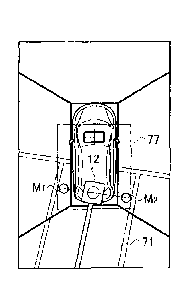
coil for supplying electric power via a wireless connection to a vehicle coil
mounted on
the vehicle, at least two ground marks indicating a position of the ground
coil, and a
parking frame, wherein a bird's-eye image including the vehicle and a
circumference of
the vehicle as viewed from above the vehicle is switched to an enlarged image
showing
a relative position between the ground coil and the vehicle coil on a larger
scale than the
bird's-eye image when an absolute value of a relative angle of a straight line
connecting
the ground marks to a straight line passing through a center of the vehicle
coil and
parallel to a vehicle width direction of the vehicle is a predetermined value
or smaller.
ADVANTAGEOUS EFFECTS
[0007]
The aspect of the present invention can provide a user with a means of easily
recognizing a relative position between the ground coil and the vehicle coil
at the right
time that the user requires.
BRIEF DESCRIPTION OF DRAWINGS
[0008]
[FIG. 1] FIG. 1 is a block diagram showing an entire configuration of a
wireless power
supply system including a parking assistance device according to an
embodiment.
[FIG. 2] FIG. 2 is a block diagram showing a specific configuration of an
image
AMENDED
SHEET
CA 03024825 2018-11-19
3
controller 55.
[FIG. 3A] FIG 3A is a top view illustrating forward parking of a vehicle I
moving
forward to enter a parking space equipped with a power supply device 100.
[FIG. 3B] FIG. 3B is a top view illustrating backward parking of the vehicle 1
moving
backward to enter the parking space equipped with the power supply device 100.
[FIG. 4A] FIG. 4A is a view showing a first example of ground marks (Mi, M2).
[FIG. 4B] FIG 4B is a view showing a second example of ground marks (MI, M2).
[FIG 4C] FIG. 4C is a view showing a third example of ground marks (MI, M2).
[FIG. 4D] FIG. 4D is a view showing a fourth example of ground marks (MI, M2,
M3,
M4).
[FIG. 4E] FIG. 4E is a view showing a fifth example of ground marks (MI, M2).
[FIG. 4F] FIG. 4F is a view showing a sixth example of ground marks (MI, M2).
[FIG. 4G] FIG. 4G is a view showing a seventh example of ground marks (MI,
M2).
[FIG. 5A] FIG. 5A is a view showing a bird's-eye image, which is an around
view
monitoring (AVM) top view, displayed on a display 53 at an early stage of a
parking
assistance operation.
[FIG. 5B] FIG. 5B is a view showing a bird's-eye image (an AVM top view)
displayed
on the display 53 in which the vehicle 1 is moving closer to the parking space
than in
FIG. 5A to decrease a relative angle of the vehicle 1 to a parking frame 71.
[FIG. 5C] FIG. 5C is a view showing an enlarged image of a relative position
between a
ground coil 12 and a vehicle coil 22 on a larger scale than the bird's-eye
image shown in
FIG. 5A and FIG. 5B.
[FIG. 6] FIG. 6 is a view showing a bird's-eye image (an AVM top view)
displayed on
the display 53 divided into four regions (86a to 86d) corresponding to cameras
(51a to
51d).
[FIG. 7] FIG. 7 is a side-view showing an arrangement example of sub-coils
(87a, 87b)
mounted on the vehicle 1.
[FIG. 8A] FIG. 8A is a view showing estimated course lines (90, 91a)
superposed on a
bird's-eye image 92 and a camera image 93'.
[FIG. 8B] FIG. 8B is a view showing estimated course lines 91b denoting
straight
CA 03024825 2018-11-19
4
movement superposed on the camera image 93'.
[FIG. 9A] FIG. 9A is a flowchart illustrating a parking assistance method
according to a
first embodiment.
[FIG. 9B] FIG. 9B is a flowchart illustrating a parking assistance method
according to a
second embodiment.
[FIG. 9C] FIG. 9C is a flowchart illustrating a parking assistance method
according to a
third embodiment.
[FIG. 9D] FIG. 9D is a flowchart illustrating a parking assistance method
according to a
fourth embodiment.
[FIG. 9E] FIG. 9E is a flowchart illustrating a parking assistance method
according to a
fifth embodiment.
[FIG. 10A] FIG. 10A is a view of an enlarged image illustrating forward
parking.
[FIG. 10B] FIG. 10B is a view of an enlarged image illustrating forward
parking.
[FIG. 10C] FIG. 10C is a view of an enlarged image illustrating backward
parking.
[FIG. 10D] FIG. 10D is a view of an enlarged image illustrating backward
parking.
DESCRIPTION OF EMBODIMENTS
[0009]
(First embodiment)
An embodiment will be described in detail below with reference to the
drawings.
[0010]
An entire configuration of a wireless power supply system including a parking
assistance device according to this embodiment is described below with
reference to
FIG. I. The wireless power supply system includes a power supply device 100
which
is a ground-side unit, a power receiving device 200 which is a vehicle-side
unit, and a
parking assistance device 300. The wireless power supply system supplies
electric
power via a wireless connection from the power supply device 100 placed in a
power
supply station, for example, to the power receiving device 200 installed in a
vehicle 1
such as an electric vehicle or a hybrid vehicle so as to charge a battery
mounted on the
CA 03024825 2018-11-19
vehicle I. The parking assistance device 300 assists a user in positioning of
the
vehicle 1 and coil alignment when the user parks the vehicle 1 in a parking
space
equipped with the power supply device 100.
[0011]
5 The power
supply device 100 includes a ground coil 12 placed in the parking
space 2 adjacent to the power supply station, and at least two ground marks
(Mi, M2)
indicating a position of the ground coil 12. The power receiving device 200
includes a
vehicle coil 22 mounted on the base of the vehicle 1. The vehicle coil 22 is
positioned
so as to be opposed to the ground coil 12 when the vehicle I is parked at a
.. predetermined stop position in the parking space.
[0012]
The ground coil 12 is a primary coil made of a conductive wire to serve as a
power transmission coil for transmitting electric power to the vehicle coil
22. The
vehicle coil 22 is a secondary coil made of a conductive wire to serve as a
power
receiving coil for receiving the electric power transmitted from the ground
coil 12.
The electric power is supplied from the ground coil 12 to the vehicle coil 22
in a
wireless manner through electromagnetic induction between the ground coil 12
and the
vehicle coil 22.
[0013]
The power supply device 100 on the ground side includes a power controller
11, the ground coil 12, a radio communication unit 13, and a controller 14.
[0014]
The power controller 11 is a circuit for converting AC power transmitted
from an AC power source 110 into high-frequency AC power and transmitting the
converted power to the ground coil 12. The power controller 11 includes a
rectifier
111, a power factor correction (PFC) circuit 112, and an inverter 113.
[0015]
The rectifier 111 is a circuit electrically connected to the AC power source
110
to rectify the AC power output from the AC power source 110. The PFC circuit
112 is
connected between the rectifier 111 and the inverter 113 to implement power
factor
CA 03024825 2018-11-19
6
correction by rectifying waveforms output from the rectifier 111. The inverter
113
includes a pulse width modulation (PWM) control circuit including a switching
device
such as an insulated gate bipolar transistor (1GBT) to convert DC power into
AC power
in accordance with a switching control signal so as to supply the AC power to
the
ground coil 12.
[0016]
The radio communication unit 13 communicates with a radio communication
unit 23 installed on the vehicle 1 side.
[0017]
The controller 14 controls the entire power supply device 100, and
particularly
controls the communication between the respective radio communication units 13
and
23. For example, the controller 14 transmits a signal for starting power
supply from
the wireless power supply device 100 toward the vehicle 1 and receives, from
the
vehicle 1 side, a request signal for requesting power supply from the wireless
power
supply device 100. The controller 14 also controls the switching operation of
the
inverter 113 and regulates the electric power transmitted from the ground coil
12.
[0018]
The power receiving device 200 on the vehicle 1 side includes the vehicle coil
22, the radio communication unit 23, a charge controller 24, a rectifier 25, a
relay 26, a
battery 27, an inverter 28, a motor 29, and a notifier 30.
[0019]
The vehicle coil 22 is positioned immediately above the ground coil 12 and
separated by a predetermined distance from the ground coil 12 when the vehicle
1 is
parked at a predetermined parking position in the parking space 2.
[0020]
The radio communication unit 23 communicates with the radio communication
unit 13 installed on the power supply device 100 side.
[0021]
The charge controller 24 controls a charging operation of the battery 27, and
further controls the wireless communication unit 23, the notifier 30, and the
relay 26,
CA 03024825 2018-11-19
7
for example. The charge controller 24 transmits a request signal for
requesting a start
of charge through the communication between the radio communication units 13
and 23
after the vehicle is parked and the coil alignment is finished.
[0022]
The rectifier 25 is a rectifying circuit connected to the vehicle coil 22 to
rectify
the AC power received by the vehicle coil 22 into DC power.
[0023]
The relay 26 includes a relay switch that is turned on/off in accordance with
the control by the charge controller 24. The relay 26 disconnects a main
circuit system
including the battery 27 from a charge circuit including the vehicle coil 22
and the
rectifier 25 when the relay switch is turned off.
[0024]
The battery 27 includes a plurality of secondary batteries connected to each
other to serve as a power source of the vehicle 1.
[0025]
The inverter 28 includes a PWM control circuit including a switching device
such as an IGBT. The inverter 28 converts DC power output from the battery 27
into
AC power and supplies the converted power to the motor 29.
[0026]
The motor 29 is, for example, a three-phase AC motor serving as a drive power
source for driving the vehicle 1.
[0027]
The notifier 30 includes a warning light, a display for a navigation system,
or a
speaker, and outputs light, images, or voice toward the user in accordance
with the
control by the charge controller 24.
[0028]
The wireless power supply system having the configuration described above
conducts the transmission and reception of high-frequency electric power in a
wireless
manner through the electromagnetic induction between the ground coil 12 and
the
vehicle coil 22. Once a voltage is applied to the ground coil 12, a magnetic
connection
CA 03024825 2018-11-19
8
is caused between the ground coil 12 and the vehicle coil 22, so that the
electric power
is supplied from the ground coil 12 to the vehicle coil 22.
[0029]
The parking assistance device 300 includes a camera 51 for capturing the
circumference of the vehicle 1, a display 53 for providing image information
to assist
the user (occupant of the vehicle 1) in positioning of the vehicle 1 and coil
alignment,
and an image controller 55 for controlling the image information.
[0030]
A specific configuration of the image controller 55 is described below with
reference to FIG. 2. The image controller 55 may be a general-purpose
microcomputer
including a memory and an input/output unit. A computer program (a parking
assistance program) is installed in the image controller 55 so as to execute a
series of
information processing to assist in the vehicle movement and the coil
alignment. The
image controller 55 implementing the program serves as information processing
circuits
(61, 62) for executing the series of information processing.
[0031]
While the present embodiment is illustrated with the case in which the
software is installed to fabricate the image controller 55, it should be
understood that
dedicated hardware such as an application specific integrated circuit (AS1C)
can be used,
instead of a general-purpose microcomputer, to compose the information
processing
circuits (61, 62). The information processing circuits (61, 62) included in
the image
controller 55 may each be composed of individual hardware. The image
controller 55
may also serve as an electronic control unit (ECU) used for other control
processing in
the vehicle 1.
[0032]
The image controller 55 acquires a camera image of the circumference of the
vehicle 1 captured. The image controller 55 functions as an image generation
circuit
61 for generating, from the camera image, a bird's-eye image including the
vehicle 1
and the circumference of the vehicle I as viewed from above the vehicle I, and
functions as a display control circuit 62 for controlling images displayed on
the display
CA 03024825 2018-11-19
9
53.
[0033]
The image generation circuit 61 uses conventional technology to generate the
bird's-eye image obtained by converting an angle of the camera image from a
position
.. of the camera 51 to a position immediately above the vehicle 1.
[0034]
The display control circuit 62 includes a parking frame estimation unit 63 for
estimating a longitudinal direction of a parking frame from at least two
ground marks
(MI, M2) shown in the camera image, for example, and a display switch unit 64
for
switching images displayed on the display 53 depending on a relative angle
between the
longitudinal direction of the parking frame and the front-rear direction of
the vehicle 1.
[0035]
The display switch unit 64 switches from the bird's-eye image to an enlarged
image showing a relative position between the ground coil 12 and the vehicle
coil 22 on
a larger scale than the bird's-eye image when an absolute value of the
relative angle
between the longitudinal direction of the parking frame and the front-rear
direction of
the vehicle 1 is a predetermined value or smaller. The display switch unit 64
displays
the bird's-eye image generated by the image generation unit 61 on the display
53 when
the absolute value of the relative angle between the longitudinal direction of
the parking
frame and the front-rear direction of the vehicle 1 is not the predetermined
value or
smaller. The display switch unit 64 displays the enlarged image on the display
53
when the absolute value of the relative angle between the longitudinal
direction of the
parking frame and the front-rear direction of the vehicle 1 is the
predetermined value or
smaller.
[0036]
When a single image is displayed on the display 53, the display switch unit 64
only needs to switch the displayed image from the bird's-eye image to the
enlarged
image. When two or more different images are displayed with different display
areas
on the display 53, the display switch unit 64 may switch a degree of
enlargement of the
display area between the bird's-eye image and the enlarged image displayed.
When
CA 03024825 2018-11-19
the absolute value of the relative angle between the longitudinal direction of
the parking
frame and the front-rear direction of the vehicle 1 is the predetermined value
or smaller,
the display switch unit 64 may switch the degree of enlargement such that the
enlarged
image has a larger display area than the bird's-eye image.
5 [0037]
While this embodiment illustrates the case in which the image controller 55 is
installed in the vehicle 1, the image controller 55 may be installed outside
the vehicle 1,
such as in the power supply device 100. In such a case, the camera image may
be
acquired through the communication between the radio communication units 13
and 23
10 so as to control the image displayed on the display 53.
[0038]
As shown in FIG. 3A, a parking frame 71 is provided on a road surface in the
parking space, and the ground coil 12 and the ground marks (MI, M2) are
arranged
inside the parking frame 71. The ground coil 12 is connected with one end of a
power
source cable 73 extending in the longitudinal direction of the parking frame
71, and the
other end of the power source cable 73 is connected to a power source box 72
placed on
the outside of the parking frame 71. The power supply device 100 shown in FIG.
1
excluding the ground coil 12 and the ground marks (Mi. M2) is housed in the
power
source box 72.
[0039]
The center of the ground coil 12 is located in the middle of a line segment
connecting the two ground marks (MI, M2). Distances 75 between the respective
centers of the ground marks (Mi, M2) and the center of the ground coil 12 are
identical
to each other. The ground marks (Mi, M2) are arranged such that a distance 74
between the respective inner ends of the ground marks (Mi, M2) is longer than
a width
76 of the vehicle 1. This prevents the two ground marks (MI, M2) from being
hidden
by the vehicle 1 when the vehicle 1 enters the parking frame 71, so as to
indicate the
both ground marks (Mi, M2) in the camera image of the circumference of the
vehicle 1
captured. The line segment connecting the ground marks (Mi. M2) is
perpendicular to
the longitudinal direction of the parking frame 71, which is the entering
direction of the
CA 03024825 2018-11-19
11
vehicle 1.
[0040]
The vehicle coil 22 is mounted on the base of the vehicle I. When the
vehicle 1 stops at a predetermined stop position in the parking space (the
parking frame
71), the vehicle coil 22 is positioned immediately above the ground coil 12.
Wheel
chocks, which are not shown in either FIG. 3A or FIG. 3B, may be provided at
positions
with which the wheels of the vehicle 1 stopping at the predetermined stop
position are
brought into contact.
[0041]
The vehicle 1 is equipped with cameras (51a, 51b, 51c, and 51d) at a front
end,
both side-view mirrors, and a rear end of the vehicle 1 for capturing images
of the
circumference of the vehicle 1. The images captured by the cameras (51a, 51b,
51c,
and 51d) are transferred to the image controller 55.
[0042]
As shown in FIG. 3B, this embodiment also employs a configuration for
backward parking which is similar to the configuration for forward parking
illustrated in
FIG. 3A. The configuration for backward parking differs from the configuration
for
forward parking in that the vehicle coil 22 is positioned closer to the side
on which the
vehicle 1 enters than the case shown in FIG. 3A when the vehicle 1 stops at
the
predetermined stop position.
[0043]
Examples of the ground marks (M1, M2) are described below with reference to
FIG. 4A to FIG. 4G. The shape of the ground marks (Mi, M2) may be any of a
circular
shape as shown in FIG. 4A, a triangular shape as shown in FIG. 4B, a
pentagonal shape
as shown in FIG. 4C, a square shape as shown in FIG. 4E, a rhombic shape as
shown in
FIG. 4F, and a rectangular shape as shown in FIG. 4G. The number of the ground
marks (M1, M2) is not limited to two. FIG. 4D illustrates a case using four
ground
marks (M1, M2, M3, M.4) in which two pairs of the ground marks (MI and M2, M3
and
M4) are provided. The center of the ground coil 12 is located at a point of
intersection
82 of the line segment 81 connecting the ground marks (M1, M2) and a straight
line 84
CA 03024825 2018-11-19
12
connecting the ground marks (M3, M4).
[0044]
This embodiment is illustrated with the case in which the center 82 of the
ground coil 12 is located in the middle of the straight line 81 connecting the
ground
marks (MI, M2), but is not limited to this case. Although not shown in the
drawings,
the center of the around coil 12 may be located at a position away from the
middle of
the straight line 81 connecting the ground marks (MI, M2) by a predetermined
distance
in the direction perpendicular to the straight line 81. For example, when the
ground
marks (M1, M2) are shifted from the center of the ground coil 12 by a
predetermined
distance toward the side on which the vehicle 1 enters, the cameras (51a to
51d) can
detect the ground marks (MI, M2) earlier. Further, the direction of the
cameras (51a to
51d) for detecting the ground marks (Mi, M2) approximates to the direction
perpendicular to the road surface, so as to improve the accuracy of detecting
the
positions of the ground marks (Mi, M2). For example, each of the shapes of the
ground marks (MI, M2) illustrated in FIG. 4A to FIG. 4G may be preliminarily
matched
with a predetermined distance, and the image controller 55 may include a
circuit which
distinguishes the shapes of the ground marks (Mi, M2), so as to acquire a
necessary
predetermined distance from the middle of the straight line 81 to the center
of the
ground coil 12 according to the corresponding shape of the ground marks (MI,
M2).
[0045]
The respective cameras (51a to 51d) capture images on the front side, the left
side, the right side, and the rear side of the vehicle 1. The image generation
unit 61
joins bird's-eye images generated from the respective camera images to
generate a
single bird's-eye image, which is an around view monitoring (AVM) top view,
surrounding all sides of the vehicle 1, as shown in FIG. 5A.
[0046]
FIG. 5A illustrates the case of backward parking in which the vehicle 1 is
moving backward to the parking space located behind the vehicle 1 and provided
with
the ground coil 12. Since the absolute value of the relative angle between the
longitudinal direction of the parking frame 71 and the front-rear direction of
the vehicle
CA 03024825 2018-11-19
13
1 is not the predetermined value or smaller in the state shown in FIG. 5A, the
display
control circuit 62 displays the bird's-eye image generated by the image
generation
circuit 61 shown in FIG. 5A on the display 53. The AVM top view presented can
provide the user with the parking assistance so as to focus on parking the
vehicle 1 in
the parking space. The user thus can operate the steering wheel appropriately
referring
to the AVM top view.
[0047]
When the relative angle between the parking frame 71 and the vehicle 1 is
decreased to a predetermined range as the operation of parking the vehicle 1
proceeds.
as shown in FIG. 5B, the user does not need to keep operating the steering
wheel. The
user thus can concentrate on the coil alignment while moving the vehicle I in
the
front-back direction. The image controller 55 determines whether the absolute
value
of the relative angle of the longitudinal direction of the parking frame 71
estimated by
the parking frame estimation unit 63 to the front-rear direction of the
vehicle 1 is the
predetermined value or smaller. When the absolute value of the relative angle
between
the longitudinal direction of the parking frame 71 and the front-rear
direction of the
vehicle 1 is determined to be the predetermined value or smaller, the display
switch unit
64 switches from the bird's-eye image to the enlarged image showing the
relative
position between the ground coil 12 and the vehicle coil 22 on a larger scale
than the
bird's-eye image, as shown in FIG. 5C. The user thus can concentrate on the
alignment of the vehicle coil 22 with the ground coil 12. Accordingly, the
parking
assistance for the wireless power supply can provide the user with the
necessary image
information (a means of easily recognizing the relative position between the
ground coil
and the vehicle coil) at the right time that the user requires.
[0048]
As shown in FIG. 5A and FIG. 5B, the display control circuit 62 displays
computer graphic (CG) images of the following elements superposed on the
bird's-eye
image:
[0049]
(1) Frames indicating outlines of the vehicle coil 22 and the ground coil 12;
CA 03024825 2018-11-19
14
(2) Two line segments 85 extending in the vehicle width direction and the
front-rear direction of the vehicle 1 and intersecting at the center of the
vehicle coil 22;
(3) The ground marks (MI, M2) confirmed by the display control circuit 62;
and
(4) The line segment 81 connecting the ground marks (MI, M2).
[0050]
For example, the display control circuit 62 displays the enlarged image of the
vehicle 1 in a region including the vehicle coil 22 and the rear side of the
vehicle coil 22
during backward parking, as shown in FIG. 5C. A region surrounded by the
dashed-dotted line 77 in FIG. 5B corresponds to the region of the enlarged
image shown
in FIG. 5C. The display control circuit 62 displays the enlarged image of the
vehicle 1
in a region including the vehicle coil 22 and the front side of the vehicle
coil 22 during
forward parking. Accordingly, the relative position between the vehicle coil
22 and
the ground coil 12 can be displayed in the enlarged image on a larger scale
than the
bird's-eye image shown in FIG. 5A and FIG. 5B.
[0051]
The parking frame estimation unit 63 calculates the line segment 81
connecting the ground marks (MI, M2) according to the ground marks (M1, M2),
and
estimates the longitudinal direction of the parking frame 71 perpendicular to
the line
segment 81 according to the line segment 81.
[0052]
The display switch unit 64 switches from the bird's-eye image as shown in
FIG. 5B to the enlarged image as shown in FIG. 5C when an absolute value of a
relative
angle of the straight line 81 connecting the ground marks (Mi, M2) to the
straight line
85 passing through the center of the vehicle coil 22 and parallel to the
vehicle width
direction of the vehicle 1, is a predetermined value or smaller.
[0053]
A parking assistance method using the parking assistance device shown in FIG.
I is illustrated below with reference to FIG. 9A. The process in the flowchart
shown
in FIG. 9A starts as the parking assistance starts, and ends when the vehicle
1 is parked
= CA 03024825 2018-11-19
at a target parking position and a gearshift is shifted to a position for
parking.
[0054]
In step S01, the parking assistance device 300 is started up. The process
proceeds to step S03 to provide the user with parking assistance information.
The
5 parking assistance information includes image information. The image
controller 55
generates a bird's-eye image as shown in FIG. 6A from camera images captured
by the
cameras (51a to 51d) installed in the vehicle 1, and displays the bird's-eye
image as the
image information on the display 53.
[0055]
10 The process proceeds to step SOS, and the image controller 55
displays a CG
image of the vehicle coil 22 superposed on the bird's-eye image. In
particular, the
image controller 55 displays CG images of the following elements superposed on
the
bird's-eye image:
[0056]
15 The frame indicating the outline of the vehicle coil 22; and
The two line segments 85 extending in the vehicle width direction and the
front-rear direction of the vehicle 1 and intersecting at the center of the
vehicle coil 22.
[0057]
The process proceeds to step S07, and the image controller 55 recognizes the
presence of the paired ground marks (MI, M2) shown in the bird's-eye image.
The
process then proceeds to step S09, and the image controller 55 confirms the
image of
the two ground marks (MI, M2). In particular, the image controller 55
determines the
shape of the ground marks (MI, M2) (a circular shape, a triangular shape, a
rectangular
shape, etc.) and a central position which is a relative position to the
vehicle I.
[0058]
The process proceeds to step S II, and the image controller 55 obtains the
central position of the ground coil 12 according to the ground marks (Mi, M2),
and
displays a CG image of the ground coil 12 superposed on the bird's-eye image.
In
particular, the image controller 55 displays CG images of the following
elements
superposed on the bird's-eye image:
CA 03024825 2018-11-19
16
[0059]
The ground marks (MI, M2) confirmed by the display control circuit 62;
The line segment 81 connecting the ground marks (MI, M2);
The frame indicating the outline of the ground coil 12;
A line segment vertical to the line segment 81 intersecting at the center of
the
ground coil 12 (the line segment 81); and
A chargeable area 78 of the ground coil 12.
[0060]
The wireless charge is available when the center of the vehicle coil 22 is
positioned within the chargeable area 78 of the ground coil 12.
[0061]
The process proceeds to step S13, and the display control circuit 62
calculates
the relative angle of the straight line 81 connecting the ground marks (Mi,
M2) to the
straight line 85 passing through the center of the vehicle coil 22 and
parallel to the
vehicle width direction of the vehicle I.
[0062]
The process proceeds to step S15, and the display control circuit 62
determines
whether the absolute value of the relative angle is a predetermined value (for
example,
five degrees) or smaller. When the absolute value of the relative angle is the
predetermined value or smaller (YES in step S15), the operation on the
steering wheel is
almost completed, so as to start the coil alignment while moving the vehicle 1
in the
front-rear direction. The process then proceeds to step S17, and the image
information
presented on the display 53 is switched from the bird's-eye image (FIG. 5B) to
the
enlarged image (FIG. 5C), so as to display the enlarged image on the display
53. This
facilitates the coil alignment since the relative position of the coils is
displayed on an
enlarged scale.
[0063]
When the absolute value of the relative angle is not the predetermined value
or
smaller (NO in step S15), the operation on the steering wheel needs to be
continued, and
the process returns to step S13 to keep displaying the bird's-eye image and
monitoring a
CA 03024825 2018-11-19
17
change of the absolute value of the relative angle.
[0064]
In step S19, the user moves the vehicle 1 in the front-rear direction to align
the
coils. The user stops the vehicle 1 when the center of the vehicle coil 22 is
positioned
within the chargeable range 78 of the ground coil 12 and turns off the
ignition of the
vehicle 1. The parking process thus ends through the steps described above.
[0065]
The first embodiment described above can achieve the following effects.
[0066]
When the absolute value of the relative angle of the longitudinal direction of
the parking frame 71 to the front-rear direction of the vehicle 1 is the
predetermined
value or smaller, the bird's-eye image is switched to the enlarged image
showing the
relative position of the ground coil 12 and the vehicle coil 22 on a larger
scale than the
bird's-eye image. The bird's-eye image is first displayed in order to focus on
the
parking assistance to lead the vehicle 1 to the parking space. When the
relative angle
of the parking frame 71 to the vehicle 1 is decreased to a predetermined
range, the
operation on the steering wheel does not need to be continued. The bird's-eye
image
is then switched to the enlarged image showing the positions of the ground
coil 12 and
the vehicle coil 22 on a larger scale. The user thus can concentrate on the
alignment of
the vehicle coil 22 with the ground coil 12. Accordingly, the parking
assistance for the
wireless power supply can provide the user with the necessary image
information (a
means of easily recognizing the relative position between the ground coil 12
and the
vehicle coil 22) at the right time that the user requires.
[0067]
The longitudinal direction of the parking frame 71 is estimated according to
the at least two ground marks (Mi, M2) shown in the camera image. The use of
the
ground marks allows the accurate estimation of the longitudinal direction of
the parking
frame 71 regardless of whether the parking frame 71 itself is recognized from
the
camera image. The parking frame 71 is not necessarily a closed frame entirely
surrounding the parking space but may be partly open. For example, the parking
CA 03024825 2018-11-19
18
frame 71 may be markers indicating four corners of a rectangular parking
space, or may
be markers indicating opposed two sides of a rectangular parking space, such
as two
sides in the vehicle width direction or two sides in the front-rear direction
of the parking
space. Accordingly, the longitudinal direction of the parking frame 71 can be
estimated regardless of whether the parking frame 71 itself is recognized from
the
camera image when the ground marks (MI, M2) are shown in the camera image so
as to
recognize the positions of the ground marks (MI, M2).
[0068]
The bird's-eye image (FIG. 5B) is switched to the enlarged image (FIG. 5C)
when the absolute value of the relative angle of the straight line 81
connecting the
ground marks (Mi, M2) to the straight line 85 passing through the center of
the vehicle
coil 22 and parallel to the vehicle width direction of the vehicle 1, is the
predetermined
value (for example, five degrees) or smaller. The straight line 81 connecting
the
ground marks (Mi, M2) is perpendicular to the longitudinal direction of the
parking
frame 71. The positioning adjustment of the vehicle 1 to the parking space is
almost
completed when the absolute value of the relative angle is the predetermined
value or
smaller, and the user only needs to move the vehicle 1 in the front-rear
direction. The
image is switched to the enlarged image at this point so as to align the
coils.
Accordingly, the image information that the user requires can be provided at
the right
time that the user requires.
[0069]
(Second embodiment)
A second embodiment illustrates an example regarding the operation of
switching from the bird's-eye image to the enlarged image under an additional
condition, added to the example of the first embodiment, that the ground marks
(Mi,
M2) are shown in both right and left regions of the bird's-eye image. A
hardware
configuration of a wireless power supply system of the second embodiment is
the same
as that of the first embodiment shown in FIG. 1, and overlapping illustrations
and
explanations are not repeated in this embodiment.
[0070]
CA 03024825 2018-11-19
19
As shown in FIG. 6, the bird's-eye image (the AVM top view) displayed on
the display 53 is divided into four regions (a front-side region 86a, a left-
side region 86b,
a right-side region 86c, and a rear-side region 86d) corresponding to the
respective
cameras (51a to 51d). The front-side region 86a corresponds to the camera 51a
provided at the front end of the vehicle I. The left-side region 86b
corresponds to the
camera 51b provided at the left side-view mirror of the vehicle I. The right-
side
region 86c corresponds to the camera 51e provided at the right side-view
mirror of the
vehicle I. The rear-side region 86d corresponds to the camera 51d provided at
the rear
end of the vehicle 1.
[0071]
The display switch unit 64 switches from the bird's-eye image (FIG. 513) to
the
enlarged image (FIG. 5C) showing the relative position between the ground coil
12 and
the vehicle coil 22 on a larger scale than the bird's-eye image when the
absolute value
of the relative angle between the longitudinal direction of the parking frame
71 and the
front-rear direction of the vehicle 1 is a predetermined value or smaller, and
the ground
marks (M1. M2) are shown in both the right-side region 86c and the left-side
region 86b
of the bird's-eye image.
[0072]
For example, when the vehicle 1 and the parking frame 71 are separated by a
distance without overlapping each other, and the absolute value of the
relative angle
between the longitudinal direction of the parking frame 71 and the front-rear
direction
of the vehicle 1 is the predetermined value or smaller, the user needs to
bring the
vehicle 1 closer to the parking space while confirming the safety around the
vehicle 1,
prior to the coil alignment. The image information for facilitating the coil
alignment is
- preferably presented after the vehicle 1 sufficiently comes close to the
parking frame 71.
[0073]
The display control circuit 62 determines that the vehicle 1 sufficiently
comes
close to the parking frame 71 when the ground marks (M1, M2) are shown in both
the
right-side region 86c and the left-side region 86b of the bird's-eye image.
The display
switch unit 64 switches from the bird's-eye image (FIG. 5B) to the enlarged
image (FIG.
CA 03024825 2018-11-19
5C) when the conditions that the absolute value of the relative angle between
the
longitudinal direction of the parking frame 71 and the front-rear direction of
the vehicle
1 is the predetermined value or smaller and that the ground marks (Mi, M2) are
shown
in both the right-side region 86c and the left-side region 86b of the bird's-
eye image are
5 both satisfied.
[0074]
A parking assistance method according to the second embodiment is illustrated
below with reference to FIG. 9B. The process in the flowchart shown in FIG. 9B
further includes step S21 between step S15 and step S17 shown in FIG. 9A. The
other
10 steps shown in FIG. 9B are the same as those in FIG. 9A, and overlapping
explanations
are not repeated below.
[0075]
When the absolute value of the relative angle between the longitudinal
direction of the parking frame 71 and the front-rear direction of the vehicle
1 is the
15 predetermined value or smaller (YES in step S15), the process proceeds
to step S21.
When the absolute value of the relative angle is not the predetermined value
or smaller
(NO in step S15), the process returns to step SI3.
[0076]
In step S21, the display control circuit 62 determines whether the ground mark
20 Mi and the ground mark M2 are respectively shown in the left-side region
86b and the
right-side region 86c of the bird's-eye image, as shown in FIG. 6.
[0077]
When the determination is a positive result in step S21, the operation on the
steering wheel is almost completed, so as to start the coil alignment while
moving the
vehicle I in the front-rear direction. The process then proceeds to step S17,
and the - -
bird's-eye image (FIG. 5B) is switched to the enlarged image (FIG. 5C) so as
to display
the enlarged image on the display 53. This facilitates the coil alignment
since the
relative position of the coils is displayed on an enlarged scale. When the
determination is a negative result in step S21, the process returns to step
S13.
[0078]
CA 03024825 2018-11-19
21
As described above, the bird's-eye image is switched to the enlarged image
when the absolute value of the relative angle between the longitudinal
direction of the
parking frame 71 and the front-rear direction of the vehicle 1 is the
predetermined value
or smaller, and the ground marks (Mi, M2) are shown in both the right-side
region 86c
and the left-side region 86b of the bird's-eye image. Since the images are
switched in
the state in which the vehicle I comes closer to a target parking position,
the necessary
image information can be presented at the point contributing to easier coil
alignment.
[0079]
(Third embodiment)
A third embodiment illustrates an example, similar to the example of the
second embodiment, regarding the operation of switching from the bird's-eye
image to
the enlarged image under a condition that the vehicle 1 sufficiently comes
close to the
parking frame 71. In particular, the third embodiment is an example regarding
the
operation of switching from the bird's-eye image to the enlarged image under
an
additional condition, added to the example of the first embodiment, that a sub-
coil
mounted on the vehicle 1 detects electric power from the ground coil 12. A
hardware
configuration of a wireless power supply system of the third embodiment is the
same as
that of the first embodiment shown in FIG. 1, except for sub-coils
additionally installed
in the vehicle 1, and overlapping illustrations and explanations are not
repeated in this
embodiment.
[0080]
An arrangement example of sub-coils (87a, 87b) mounted on the vehicle 1 is
described below with reference to FIG. 7. Each of the sub-coils (87a, 87b) is
made of
a conductive wire and has a smaller size and a smaller wound number than the
vehicle
coil 22 and the ground coil 12. The sub-coil 87a is provided at a front end of
the base
of the vehicle 1, and the sub-coil 87b is provided at a rear end of the base
of the vehicle
I. As shown in FIG. 7, when the vehicle I makes forward parking by moving
forward
to approach the ground coil 12, the sub-coil 87a detects electric power from
the ground
coil 12 prior to the vehicle coil 22. The vehicle 1 thus can be determined to
come
closer to the parking space due to the detection by the sub-coil 87a. When the
vehicle
CA 03024825 2018-11-19
22
I makes backward parking by moving backward to approach the ground coil 12,
the
sub-coil 87b detects electric power from the ground coil 12.
[0081]
The display switch unit 64 switches from the bird's-eye image to the enlarged
image when the absolute value of the relative angle between the longitudinal
direction
of the parking frame 71 and the front-rear direction of the vehicle 1 is a
predetermined
value or smaller, and either of the sub-coils (87a, 87b) mounted on the
vehicle 1 detects
electric power from the ground coil 12.
[0082]
A parking assistance method according to the third embodiment is illustrated
below with reference to FIG. 9C. The process in the flowchart shown in FIG. 9C
further includes step S23 between step S15 and step S17 shown in FIG. 9A. The
other
steps shown in FIG. 9C are the same as those in FIG. 9A, and overlapping
explanations
are not repeated below.
[0083]
When the absolute value of the relative angle between the longitudinal
direction of the parking frame 71 and the front-rear direction of the vehicle
1 is the
predetermined value or smaller (YES in step S15), the process proceeds to step
S23.
When the absolute value of the relative angle is not the predetermined value
or smaller
(NO in step S15), the process returns to step S13.
[0084]
In step S23, the display control circuit 62 determines whether either of the
sub-coils (87a, 87b) mounted on the vehicle 1 shown in FIG. 7 detects electric
power
from the ground coil 12.
[0085]
When the determination is a positive result in step S23, the operation on the
steering wheel is almost completed, so as to start the coil alignment while
moving the
vehicle 1 in the front-rear direction. The process then proceeds to step S17,
and the
display switch unit 64 switches from the bird's-eye image to the enlarged
image so as to
display the enlarged image on the display 53. This facilitates the coil
alignment since
CA 03024825 2018-11-19
23
the relative position of the coils is displayed on an enlarged scale. When the
determination is a negative result in step S23, the process returns to step
S13.
[0086]
According to the third embodiment as described above, the image information
.. for facilitating the recognition of the relative position between the
ground coil 12 and
the vehicle coil 22 can be presented at the point when the vehicle 1
sufficiently comes
close to the parking space and the relative angle between the vehicle 1 and
the parking
frame 71 is sufficiently decreased.
[0087]
(Fourth embodiment)
A fourth embodiment illustrates an example regarding the operation of
determining that the absolute value of the relative angle between the
longitudinal
direction of the parking frame 71 and the front-rear direction of the vehicle
1 is a
predetermined value or smaller when the steering wheel provided in the vehicle
1 is in a
neutral position. The fourth embodiment uses the ground marks (Mi, M2) and the
straight line 81 connecting the ground marks (Mi. M2) for detecting the
position of the
ground coil 12, not for estimating the longitudinal direction of the parking
frame 71.
A hardware configuration of a wireless power supply system of the fourth
embodiment
is the same as that of the first embodiment shown in FIG. 1, and overlapping
illustrations and explanations are not repeated in this embodiment.
[0088]
The display switch unit 64 switches from the bird's-eye image to the enlarged
image when the steering wheel provided in the vehicle 1 is in a neutral
position. As
used herein, the phrase "the steering wheel in a neutral position" refers to a
state in
which an absolute value of a steering angle of the steering wheel is a
predetermined
steering reference value (for example, three degrees) or smaller. The phrase
also refers
to a state in which an absolute value of a turning angle of the wheels is a
predetermined
turning reference value or smaller.
[0089]
A parking assistance method according to the fourth embodiment is illustrated
CA 03024825 2018-11-19
24
below with reference to FIG. 9D. The process in the flowchart shown in FIG. 9D
includes step S25 instead of step SI3 and step S15 shown in FIG. 9A. The other
steps
shown in FIG. 9D are the same as those in FIG. 9A, and overlapping
explanations are
not repeated below.
[0090]
In step S25, the display control circuit 62 monitors the steering wheel of the
vehicle 1 until the steering wheel is located in the neutral position. When
the
determination is a positive result in step S25, the operation on the steering
wheel is
almost completed, so as to start the coil alignment while moving the vehicle I
in the
front-rear direction. The process then proceeds to step S17, and the display
switch unit
64 switches from the bird's-eye image to the enlarged image so as to display
the
enlarged image on the display 53. This facilitates the coil alignment since
the relative
position of the coils is displayed on an enlarged scale.
[0091]
According to the fourth embodiment as described above, the enlarged image
for facilitating the coil alignment can be presented at the point when the
positioning
adjustment of the vehicle 1 to the parking space is almost completed and the
user only
needs to move the vehicle 1 in the front-rear direction.
[0092]
(Fifth embodiment)
A fifth embodiment exemplifies an example regarding the operation of
determining that the absolute value of the relative angle between the
longitudinal
direction of the parking frame 71 and the front-rear direction of the vehicle
1 is a
predetermined value or smaller when estimated course lines displayed on the
display 53
denote straight movement. The fifth embodiment uses the ground marks (Mi,-M2)
and
the straight line 81 connecting the ground marks (MI, M2) for detecting the
position of
the ground coil 12, not for estimating the longitudinal direction of the
parking frame 71.
A hardware configuration of a wireless power supply system of the fifth
embodiment is
the same as that of the first embodiment shown in FIG. 1, and overlapping
illustrations
and explanations are not repeated in this embodiment.
CA 03024825 2018-11-19
[0093]
The image controller 55 estimates a course of the vehicle I according to a
steering angle of the steering wheel or a turning angle of the wheels of the
vehicle 1,
and displays lines (estimated course lines) (90, 91a) indicating the estimated
course of
5 the vehicle I superposed on a bird's-eye image 92 or a camera image 93'
captured by
the camera 51d, as shown in FIG. 8A or FIG. 8B. The estimated course lines
(90, 91a)
extend from rear ends or front ends of both side surfaces of the vehicle I. As
the
absolute value of the turning angle or the steering angle is smaller, the
curvature of the
respective estimated course lines decreases to approximate to a straight line.
A shown
10 in FIG. 8B, when the estimated course lines 91b indicate straight
movement, the
steering angle or the turning angle can be determined to be approximately zero
degrees.
[0094]
A parking assistance method according to the fifth embodiment is illustrated
below with reference to FIG. 9E. The process in the flowchart shown in FIG. 9E
15 includes step S27 instead of step S13 and step S15 shown in FIG. 9A. The
other steps
shown in FIG. 9E are the same as those in FIG. 9A, and overlapping
explanations are
not repeated below.
[0095]
In step S27, the display control circuit 62 monitors the estimated course
lines
20 until the estimated course lines displayed on the display 53 indicate
straight movement.
When the determination is a positive result in step S27, the steering wheel
can be
determined to be in the neutral position. The operation on the steering wheel
is thus
almost completed, so as to start the coil alignment while moving the vehicle 1
in the
front-rear direction. The process then proceeds to step SI7. and the display
switch unit
25 64 switches from the bird's-eye image to the enlarged image so as to
display the
enlarged image on the display 53. This facilitates the coil alignment since
the relative
position of the coils is displayed on an enlarged scale.
[0096]
According to the fifth embodiment as described above, the enlarged image for
facilitating the coil alignment can be presented at the point when the
positioning
CA 03024825 2018-11-19
26
adjustment of the vehicle 1 to the parking space is almost completed and the
user only
needs to move the vehicle 1 in the front-rear direction.
[0097]
The functions described in the respective embodiments may be implemented in
one or more processing circuits. A processing circuit includes a programmed
processing device such as a processing device including an electric circuit.
Such a
processing device includes an application specific integrated circuit (ASIC)
configured
to execute the functions described in the respective embodiments or
conventional circuit
components.
[0098]
While the present invention has been described above with reference to the
embodiments, it should be understood that the present invention is not
intended to be
limited to the embodiments described above, and various modifications and
improvements will be apparent to those skilled in the art within the scope of
the present
invention.
[0099]
The enlarged image is not limited to the example shown in FIG. 5C, and may
be any of images as illustrated in FIG. 10A to FIG. 10D. The enlarged images
shown
in FIG. 10A to FIG. 10D differ from the enlarged image shown in FIG. 5C in the
aspect
ratio, in which the length in the vehicle width direction is longer than the
length in the
front-rear direction of the vehicle 1. The enlarged images shown in FIG. 10A
to FIG.
10D are thus preferably used as switched images at the point when the distance
between
the coils is decreased more than that shown in FIG. 5C.
[0100]
FIG. 10A and FIG. 10B illustrate forward parking, and FIG. 10C and FIG.
10D illustrate backward parking. FIG. 10A and FIG. IOC each show CG images of
the following elements superposed on the bird's-eye image:
[0101]
The frame indicating the outline of the vehicle coil 22; two line segments
(85,
93) extending in the vehicle width direction and the front-rear direction of
the vehicle 1
CA 03024825 2018-11-19
27
and intersecting at the center of the vehicle coil 22; the ground marks (MI,
M2); the line
segment 81 connecting the ground marks (Mi, M2); the frame indicating the
outline of
the ground coil 12; a line segment 83 vertical to the line segment 81
intersecting at the
center of the ground coil 12 (the line segment 81); and the chargeable area 78
of the
ground coil 12.
[0102]
FIG. 10B and FIG. 10D illustrate images in which the bird's-eye images are
eliminated from FIG. 10A and FIG. 10C and the coil parts are further enlarged.
The
CG images of the frame indicating the outline of the vehicle coil 22 and the
frame
indicating the outline of the ground coil 12 are eliminated from FIG. 10A and
FIG. 10C.
The unnecessary images for the coil alignment are eliminated, so as to further
facilitate
the coil alignment.
REFERENCE SIGNS LIST
[0103]
1 Vehicle
2 Parking space
12 Ground coil
22 Vehicle coil
53 Display
55 Image controller
61 Image generation circuit
62 Display control circuit
71 Parking frame
86b Left-side region
86c Right-side region
87a, 87b Sub-coil
90, 91a, 91b Estimated course line
92 Bird's-eye image
93' Camera image
CA 03024825 2018-11-19
28
M1, M2 Ground mark