Note: Descriptions are shown in the official language in which they were submitted.
CA 03025244 2018-11-22
WO 2017/203462 PCT/IB2017/053085
1
A MINI-INVASIVE DEVICE FOR THE ENDOUROLOGIC TREATMENT.
The present invention relates to a mini-invasive device for endourologic
treatments.
At present, the endourologic treatment of urinary calculosis provides for
the introduction, within the operating channel of specific endoscopes, of
tools
useful for the treatment of calculosis itself. These tools are essentially
divided
into two types: those adapted to reduce the stone in a series of fragments of
suitable dimensions suitable for natural extraction by the human body, and
those aimed at mobilizing the stone itself or at the direct extraction of the
fragments.
Among the devices of this second type are grippers specifically
designed to grab the stone fragments. In particular, the largest endoscopes,
with a rigid structure, allow the use of very large grippers, which are
particularly
effective in terms of grip and extraction. Moreover, also small endoscopes,
with
a flexible structure, allow the passage of small grippers within their
operating
channel.
While grippers are economically advantageous in that, after
sterilization, can be reused, they are nevertheless ineffective in most cases.
In
particular, the grippers, due to their specific conformation as well as to the
material of which they are made, once introduced inside the endoscope cause
the stiffening of the latter and a reduction in its flexibility. This greatly
affects
the effectiveness of the endoscope itself, limiting its ability to reach
peripheral
areas of the urinary tract, especially in cases where the target stone is "out
of
axis", that is, misaligned with respect to the entrance of the endoscope.
CA 03025244 2018-11-22
WO 2017/203462 PCT/IB2017/053085
2
Moreover, the operation of the grippers is compromised beyond a
certain curvature thereof. In particular, beyond a certain limit value, the
angularity of the bearing structure compromises the transmission of the
mechanical control from the handpiece to the clamps of the grippers, thereby
preventing the opening of the mouth thereof.
As an alternative to grippers, among the devices aimed at mobilizing
the stone and/or at the direct extraction of the fragments thereof, the so-
called
baskets are also known. These are extremely thin and flexible devices that can
be introduced into the body through the endoscope's operating channel. They
are maneuverable through an outer handpiece that controls the opening of
metal coils on the lithiasic fragment. In particular, such coils, by reclosing
themselves as a network on the target stone fragment, envelop it so as to
allow
the mobilization or extraction thereof.
The basket devices overcome all the drawbacks of grippers since,
having a thinner structure, they compromise the flexibility of the endoscope
in
which they are introduced to a lesser extent. In addition, unlike the
grippers,
they can open on the target even under highly angled conditions.
However, also the basket devices are not completely satisfactory.
Firstly, being disposable devices, they add a specific cost to each surgical
procedure. In addition, it is often difficult to block the stone fragment
within the
coils, either because it is too large to be completely enveloped in the coils
or,
conversely, because the fragments are so small that they emerge from the coil
loops, while the same close. In essence, basket devices cannot be used for the
removal of particularly large or particularly small stone fragments.
CA 03025244 2018-11-22
WO 2017/203462 PCT/IB2017/053085
3
A further drawback relates to the operational difficulty associated with
the impossibility of enveloping the stone when the same is off the axis with
respect to the opening of the basket coils.
In addition, after some steps and attempts to remove the lithiasis
fragments, the basket operation is compromised, and this can lead to an
extremely difficult release of the stone fragment, once it has been gripped,
if it
is considered too large to be extracted whole. Therefore, if the basket device
operation is compromised, it must inevitably be replaced, with further
economic
expenditure. Moreover, the endoscopic maneuvers necessary to resolve this
complication can be complex and cause in turn additional clinical
complications.
Ultimately, all these technical and operational difficulties of the basket
device involve a lengthening of the operating time.
US 2004/0019358 describes a device that includes an elongated
element defining a hollow suction conduit. In particular, this elongated
element
is flexible lengthwise, is configured to be inserted within the operating
channel
of a ureteroscope and is also able to withstand the deformation caused by
suction. More in detail, the proximal portion of the elongated element is in
communication with a vacuum source able to provide the suction within the
conduit, while the distal portion of the elongated element itself projects
from the
ureteroscope and is intended to come into contact with the object to be
treated
in the patient's body. US 2004/0019358 describes in detail the use of the
elongated element for capturing, retaining, moving/removing a kidney stone
when the latter is embedded in a tissue or is located in a part of the
patient's
body that is difficult to access using traditional instruments (baskets or
grippers). However, in all these applications, it is provided that the
conduit,
CA 03025244 2018-11-22
WO 2017/203462 PCT/IB2017/053085
4
defined within the elongated element, always and only acts as a suction
conduit.
In fact, US 2004/0019358 teaches at most to retract the elongated element from
the ureteroscope and insert within the ureteroscope itself, as an alternative
to
the elongated element defining the suction conduit, another surgical
instrument
for removing the stone.
US 5102415, WO 99/45835, US 2002/188313 and WO 2012/156924
relate to devices used in cardiology, not in the endourologic context. In
particular, in the context of cardiology, the use of the endoscope is not
involved
and, therefore, the technical issues are different from those in the
endourologic
context, where the use of the endoscope is involved.
US 6375651 describes a device that comprises a suction conduit and a
conduit for energy transmission, which can be coextruded, attached to or
separate from each other, or one inside the other. In addition, the casing of
the
device may accommodate a plurality of components, such as laser fibers,
optical fibers and catheters and guide wires. However, in all the embodiments
described in US 6375651, there are always two conduits, one of suction and
one for the laser fiber, which are separate from each other. In particular,
the
laser fiber conduit can also be placed within the suction conduit, but in any
case
they must be separate. Last but not least, the fact that the outer tubular
casing,
inside of which the suction conduit and the laser conduit are separately
formed,
internally has a particularly thick circular crown which has a particularly
reduced
flexibility lengthwise.
US 7540868 describes a device provided with an elongated element
connected to a suction tube and inside of which a laser fiber is inserted
which
is secured with a clip at the distal portion of the elongated element. The
CA 03025244 2018-11-22
WO 2017/203462 PCT/IB2017/053085
presence of the clip does not allow the removable insertion of the laser fiber
and, in any case, does not allow the removable insertion of other gripping
tools,
such as grippers or the basket, used in endourologic treatments. In addition,
US 7540868 requires that the elongated element is connected to the suction
5
connector via a suction tube, which is housed inside the casing of the device.
Last but not least, the fact that the elongated element of US 7540868 does not
have a non-deformable inner lumen.
U54692139 describes a catheter for removing obstructions that are
present in a biological channel that comprises an insertion sleeve (and not an
endoscope) inside which a flexible vacuum tube is inserted which is connected
with the proximal end thereof to a suction source. Moreover, a small tube is
inserted within the suction tube for the injection of medical substances and
an
ultrasound probe. In this solution, the suction tube has on the outer surface
a
male thread that cooperates and engages with a corresponding female thread
which is provided on the inner surface of the insertion sleeve in order to
allow
a controlled sliding of the suction tube inside the sleeve. Moreover, a
locking
ring of the distal end of the vacuum tube is provided at the distal tip of the
sleeve
in order to prevent the latter from protruding beyond the distal tip of the
sleeve
itself.
U55417697 describes a solution for removing a polyp from a patient's
colon. This solution comprises a device for endoscopic surgery with an
elongated tubular conduit insertable within a channel of an endoscope. In
particular, at the distal end thereof, the tubular conduit has a cup-shaped
portion from which a cauterization ring protrudes which is powered with
electric
current to cut the polyp from the patient. In addition, the tubular conduit is
CA 03025244 2018-11-22
WO 2017/203462 PCT/IB2017/053085
6
provided with suction to allow the polyp removed to enter within the conduit
itself. As shown in the figures, the tubular conduit of US5417697 does not
have
a substantially non-deformable lumen, but indeed it must just be deformable in
order to allow the entry of the polyp removed.
DE 19842113 describes a solution for extracting stents or blood clots
from blood vessels. This solution comprises a first extraction catheter, which
consists of a tubular conduit with three expandable portions at its distal tip
which
open to define a funnel. In particular, this extraction catheter is inserted
through
and entirely crosses a second introducer catheter, so that by protruding from
the latter, the tip of the first one opens as a funnel. More in detail, the
second
introducer catheter consists of a cover sleeve, having smaller length than the
extraction catheter and which is slidable along the latter. It is also
possible to
suction the clot within the extraction catheter and this means necessarily
that
the lumen of such a catheter should be deformable.
US5417697 and DE19842113 do not describe devices for the
endourologic treatment and, in particular, it is clear that the deformability
of the
lumen of the tubular conduit of US5417697 of the extractor catheter of DE
19842113 makes these solutions unsuitable and incompatible with the needs
and the suction values required in the endourologic context, for example for
.. capturing and mobilizing the stones.
The object of the invention is to overcome all these drawbacks by
providing a mini-invasive device for the endourologic treatment that overcomes
the drawbacks of traditional devices and that is both alternative and
ameliorative with respect to these.
CA 03025244 2018-11-22
WO 2017/203462 PCT/IB2017/053085
7
Another object of the invention is to provide a device adapted to be used
in combination with one or more tools used for the endourologic treatment,
such
as a lithotripsy laser source and/or a gripping tool and/or a catheter for
injecting
substances.
Another object of the invention is to provide a device which, while having
a small size, is particularly effective and more specifically capable of
reaching
even the most peripheral districts of the urinary tract.
Another object of the invention is to provide a device that does not
obstruct the flexibility of the endoscope within which it is inserted.
Another object of the invention is to implement a device that has high
accuracy, reliability and safety.
Another object of the invention is to implement a device that is
multifunctional and that reduces the surgery time.
Another object of the invention is to implement a device with an
alternative characterization, in constructional, functional and performance
terms, compared to the traditional ones.
Another object of the invention is to implement a device that can be
obtained in a simple, quick and cost-effective manner.
These objects, both alone or in any combination thereof, and others that
will appear from the following description are achieved, according to the
invention, with a device having the features indicated in claim 1.
The present invention is further clarified hereinafter in a preferred
embodiment thereof described by way of non-limiting example only with
reference to the accompanying drawings, in which:
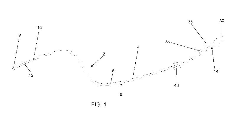
Figure 1 shows a schematic view of the device according to the invention,
CA 03025244 2018-11-22
WO 2017/203462 PCT/IB2017/053085
8
Figure 2 shows a schematic and detailed view of the components of the device
in fig. 1,
Figure 3 shows a longitudinal section of an enlarged detail of the distal end
of
the device in fig. 1 with a guide inserted therein,
Figure 4 shows it according to view IV-IV in fig. 3,
Figure 5 shows a partial longitudinal section view of an enlarged detail of
the
device in fig. 1 without the guide,
Figure 6 shows a cross-section view of an endoscope, in which the device in
fig. 1 can be inserted,
Figure 7 shows a schematic enlarged view of the device according to the
invention in which a laser fiber used in the endourologic treatment
has been inserted,
Figure 8 shows a schematic enlarged view of the device according to the
invention in which an injection catheter used in the endourologic
treatment has been inserted.
As can be seen in the figures, the mini-invasive device 2 according to
the invention comprises a tubular conduit 4 having:
- a central portion 6 intended to cross the entire operating channel 8 of an
endoscope 10,
- a portion 12 which in operation is distal and is intended to project from
the
inner end of endoscope 10, inserted in the patient's body, in order to reach
the target to be treated,
- a portion 14 which in operation is the proximal one and is intended to
project
from the outer end of endoscope 10 and to be connected to suction means,
not shown.
CA 03025244 2018-11-22
WO 2017/203462 PCT/IB2017/053085
9
The tubular conduit 4 internally delimits a suction conduit 5 and, within
the latter, one or more tools used in the endourologic treatment and can be
removably inserted, preferably a laser source 33 for lithotripsy, a gripping
tool
and/or a catheter 41 for injecting substances. Suitably, the suction conduit
5,
defined by the tubular conduit 4, is configured so that multiple tools used in
the
endourologic treatment can be inserted simultaneously within the conduit
itself
or one at a time.
Advantageously, the suction conduit 5, within which at least one tool
used in the endourologic treatment can be removably inserted, is entirely and
solely delimited by the inner walls of the tubular conduit 4.
The tubular conduit 4 of device 2 has a high longitudinal flexibility,
substantially along its entire longitudinal development, and at the same time
has a high transverse deformability, i.e. it is able to maintain the lumen
defined
therein unaltered even when it is subjected to contraction forces due to
internal
suction, and/or to compression forces caused by the irrigation flow, which
acts
on the outer surface of the conduit itself.
Preferably, the distal portion 12 of the tubular conduit 4 has greater
longitudinal flexibility than the remaining part of the tubular conduit
itself. More
in detail, the central 6 and/or proximal 14 portions of the tubular conduit 4
have
such longitudinal flexibility features as to allow a radius of curvature of at
least
20 cm substantially by the whole length thereof, while the distal portion 12
of
said conduit 4, which is preferably about 10 cm long, has a greater
flexibility
such as to allow reaching a radius of curvature of about 1.5 cm.
The tubular conduit 4 is made of thin and biocompatible plastic material,
for example polytetrafluoroethylene (PTFE), polyether block amide (PEBA),
CA 03025244 2018-11-22
WO 2017/203462 PCT/IB2017/053085
thermoplastic polymers with highly flexible medical grade, polyurethane (PU),
polyethylene (PE) and/or other materials commonly used for the manufacture
of medical tubes and catheters.
Inside the tubular conduit 4, which comprises the central 6, distal 12
5 and proximal 14 portions, a reinforcement armor 16 may advantageously be
associated. It may preferably be made of metal, for example titanium alloys,
Nitinol or other high-flexibility metals with thermal memory and is designed
to
ensure the non-deformability of the inner lumen; to this end, it may have a
spiral
or "X" mesh crossed pattern, developing by the entire tubular conduit 4 or,
10 alternatively, only in certain areas, specifically in the distal portion
12.
In particular, said longitudinal flexibility and transverse non-
deformability features of the tubular conduit 4 mainly derive from the elastic
modulus of the material of which the conduit itself is made and/or from the
density and type ("X" meshes or spiral) of the reinforcement armor 16.
The central portion 6 of the tubular conduit 4 has a substantially
constant diameter 24 throughout the entire development thereof. Preferably,
the central portion 6 of the tubular conduit 4 is made with a mesh of Nitinol
coated with hydrophilic PTFE; this allows a high flowability of the flows
internal
and external to the conduit as well as a high longitudinal flexibility and a
high
transverse non-deformability.
The distal portion 12 of the tubular conduit 4, that is, the portion
intended to project from endoscope 10 to reach the target, consisting, for
example, of a stone fragment to be mobilized or to be removed, comprises a
truncated-cone termination 18 extending outwards so as to define a greater
useful surface at end 20 for the coupling with the target. In particular, the
inner
CA 03025244 2018-11-22
WO 2017/203462 PCT/IB2017/053085
11
diameter 22 of end 20 of termination 18 is greater, up to a maximum of 20%,
preferably about 10%, with respect to the inner diameter 24 of the central
portion 6 of the tubular conduit 4.
Alternatively, termination 18 may also have a cylindrical shape such that
the inner diameter 22 of end 20 is substantially equal to the inner diameter
24
of the central portion 6 of the tubular conduit 4.
Suitably, the tools used in the endourologic treatment are inserted into
the suction conduit 5 so that their respective end projects from termination
18
of the tubular conduit 4 which internally delimits said suction conduit.
Moreover, as shown in fig. 5, at section 26 from which termination 18
branches off, the inner diameter 28 of the distal portion 12 narrows,
preferably
by about 10%, with respect to the inner diameter 24 of the central portion 6.
This prevents the entry into the tubular conduit 4 of stones, or fragments
thereof
or other biological or fluid components, having a size comparable to that of
the
inner diameter of said conduit 4. Suitably, the part of distal portion 12 that
is not
affected by termination 18 and by the narrowing section 26 has an inner
diameter substantially equal to the inner diameter 24 of the central portion 6
of
the tubular conduit 4.
The tubular conduit 4 has transverse non-deformability features
substantially equal and constant across the longitudinal development thereof;
however, suitably, termination 18 of the distal portion 12 may be transversely
deformable.
Preferably, at least termination 18 of the distal portion 12 comprises a
coil of unifilar Nitinol immersed in soft polyurethane (soft PU) coated with a
hydrophilic film.
CA 03025244 2018-11-22
WO 2017/203462 PCT/IB2017/053085
12
The proximal portion 14 of conduit 4, that is, the opposite portion with
respect to the distal one 12, comprises a first connector 30 for the
connection
to suction means, such as a vacuum generator. Moreover, the proximal portion
14 comprises a second connector 32 for the connection to the operating
channel 8 of endoscope 10; preferably, the latter is movable along the
longitudinal development direction of the tubular conduit 4 and in this way,
the
length of the proximal portion 14 projecting from endoscope 10 can be
adjusted.
Both connectors are coaxial to the development direction of the tubular
conduit 4. More in detail, moreover, connectors 30 and 32 comprise means
(30a, 32a, respectively), for example consisting of a threaded area, for the
attachment to respective couplings, and means (30b, 32b) for allowing and
facilitating the grip of each connector by the surgeon or the operator.
Preferably, the proximal portion 14 is made of thermoplastic material,
such as PE.
Moreover, the proximal portion 14 of the tubular conduit 4 comprises a
tubular section 34, which bifurcates with respect to the main section 36, to
define a lateral access intended for the introduction of a laser fiber 33
within the
lumen of the tubular conduit 4 (see fig. 7). In particular, at the entrance of
this
bifurcated section 34, a valve 38 is provided for the adjustment and
maintenance of a negative pressure within the lumen of the tubular conduit 4
in
order to prevent the interruption of the suction made by the device itself.
Around the outer surface of the tubular conduit 4 of device 2, a
cylindrical body 40 is applied which acts as a safety lock for inserting the
device
itself into endoscope 10.
CA 03025244 2018-11-22
WO 2017/203462 PCT/IB2017/053085
13
Preferably, device 2 according to the invention also comprises an inner
guide 42 removably insertable into the tubular conduit 4 to insert the latter
into
the operating channel 8 of endoscope 10.
In particular, the inner guide 42 comprises a rod which can be
removably inserted within the tubular conduit 4 which is advantageously
provided at the distal end thereof with means for keeping the tubular conduit
extended during the insertion step of the latter within the operating channel
8
of endoscope 10. Preferably, the rod of guide 42 has a termination with two
diametric appendages 44 intended to fit into corresponding diametrically
opposed rings 46 provided at the end of termination 18 of the distal portion
12.
Preferably, guide 42 is made of substantially rigid PE.
In particular, guide 42 comprises:
- a proximal portion 47 with a connector 48 thereof for the attachment to
connector 30 of the tubular conduit 4; in particular, also connector 48
comprises means 48a (such as a threaded section) for the attachment of
connector 30, and means for gripping by the surgeon or operator;
- a central portion 50 intended to cross the central portion 6 and part of
the
distal portion 12 of the tubular conduit 4; in particular, portion 50 develops
substantially by the entire length of the central portion 6 of the tubular
conduit
4 and has a section just smaller than the inner diameter 24 of the central
portion itself,
- a distal portion 52 intended to cross termination 18 of the distal
portion 12 of
the tubular conduit 4; in particular, portion 52 has a slightly smaller
section
than the inner section 24 of the tubular conduit 4 in order to overcome the
shrinkage defined at section 26.
CA 03025244 2018-11-22
WO 2017/203462 PCT/IB2017/053085
14
The dimensions of device 2 depend on the type of endoscope used and
in any case, the outer diameter 54 of the central portion 6 of the tubular
conduit
4 ranges between about 1 mm (equal to 3Fr) and about 10 mm.
Moreover, the length of the central portion 6 of the tubular conduit 4 is
.. substantially at least 1 mm longer than the length of the operating channel
8 of
endoscope 10; in particular, in the case of flexible uretero-nephroscopes,
such
a length is equal to about 681 mm.
The proximal portion 14 of the tubular conduit 4 may be any length and,
by way of example only, it may be of between 5 and 10 cm.
More in detail, in the case of a device 2 in which the outer diameter 54
of the central portion 6 of the tubular conduit 4 is about 1 mm (i.e. about
3Fr),
the inner diameter 24 of said portion is preferably about 0.8 mm, the inner
diameter 28 at the narrowing section 26 is about 0.72 mm while at end 20,
diameter 22 is about 0.9 mm; in addition, preferably, with said sizes, length
56
.. of termination 18 is about 0.5 mm.
Device 2 according to the invention can be used with any endoscopic
instrument provided with one or more operating channels, and with further
support channels 58 and 60, respectively, for lighting and for the optical
fibers.
For example, these endoscopic instruments include a flexible uretero-
nephroscope for kidney stones, a rigid or flexible cystoscope for bladder
stones,
a rigid ureteroscope for ureteral stones and a rigid or flexible nephroscope
for
kidney or ureteral stones.
The operation of device 2 according to the invention clearly appears
from the foregoing.
CA 03025244 2018-11-22
WO 2017/203462 PCT/IB2017/053085
At first, the inner guide 42 is inserted into the tubular conduit 4 and is
locked, through connector 48 thereof, to connector 30 of said conduit. Then,
device 2 thus configured can be easily inserted through the operating channel
8 of endoscope 10 and can allow the distal portion 6 to project from the end
of
5 the endoscope inserted into the patient's body.
The inner guide 42 of device 2 substantially serves to facilitate the
introduction of the device itself within endoscope 10. In fact, the inner
guide 42
keeps device 2 always extended and thus prevents it from swelling due to the
compression thrust necessary for its insertion within the operating channel 8.
10 Once device 2 has been completely introduced into endoscope 10, the
inner guide 42 of device 2 is extracted from the tubular conduit 4. In
particular,
during the insertion of device 2, guide 42 is fixed by its connector 48 to
connector 30 of the tubular conduit 4. Once said insertion step has finished,
connector 48 of guide 42 is disconnected from connector 30 of the tubular
15 conduit 4 and the guide itself is extracted from the tubular conduit 4
so that
connector 30 of the proximal portion 14 of the tubular conduit 4 can be
connected to the coupling of the suction means.
At this point, the surgeon/operator can maneuver endoscope 10 until he
reaches the stone and, once reached, he activates the suction means which
through the suction flow first attract and then retain the stone at end 20 of
termination 18 of the distal portion 6 of device 2. Moreover, if it is
necessary to
release and remove the fragment from the distal end 6 of device 2, it is
sufficient
to stop the suction.
Then, always through the suction, the stone thus retained may be
mobilized as needed or be extracted from the urinary excretory way. More in
CA 03025244 2018-11-22
WO 2017/203462 PCT/IB2017/053085
16
detail, once the stone has been captured at end 20 of device 2, the surgeon
may remove endoscope 10 from the patient's body and simultaneously extract
the stone retained by device 2 inserted into the operating channel 8 of the
endoscope itself.
As said, if clinically indicated, it is also possible to introduce, through
the bifurcated section 34, within the suction conduit 5, which is delimited by
the
tubular conduit 4, a laser fiber 33 or other surgical tools (see figs. 7 and
8).
Advantageously, the insertion of the laser fiber 33 within the suction
conduit 5 allows the laser fragmentation of the stone, while the lithiasic
powder
thus produced is suctioned by the suction means within the suction conduit 5
defined by the tubular conduit 4. Suitably, the laser fiber 33 may also be
used
for treatments other than calculosis, for example, it may be used at modulated
frequency and energy for the ablation of the excretory pathway lesions.
More in detail, as shown in fig. 7, the laser fiber 33 is inserted into the
suction conduit 5 through the bifurcated section 34 and at the outer end of
the
latter, a suitable coupling element 35 with the outer fiber 37 associated with
a
laser generator (not shown) is provided. Suitably, the laser fiber 33 is
inserted
into the suction conduit 5 so that end 39 thereof projects from termination 18
of
the tubular conduit 4.
Advantageously, into the suction conduit 5 delimited by the tubular
conduit 4, gripping tools may be introduced, such as baskets, for capturing
and
retaining the stone or any foreign bodies, so as to facilitate its extraction
from
the urinary excretory pathway. Moreover, when required, within the suction
conduit 5 delimited by the tubular conduit 4, dedicated grippers may be
CA 03025244 2018-11-22
WO 2017/203462 PCT/IB2017/053085
17
introduced to perform biopsies. Suitably, the gripping tool is inserted into
the
suction conduit 5 so as to project from termination 18 of the tubular conduit
4.
Advantageously, within the suction conduit 5 delimited by the tubular
conduit 4, a catheter 41 for injecting substances may be introduced in order
to
perform a topical treatment, such as chemotherapy, haemostatic, contrast
graphic, drainage or other. Suitably, cathether 41 is inserted into the
suction
conduit 5 so that end 43 thereof projects from termination 18 of the tubular
conduit 4. More in detail, as shown in fig. 8, catheter 41 is inserted into
the
suction conduit 5 through the bifurcated section 34 and at the outer end of
the
.. latter, a suitable coupling element 45 is provided. In addition, outside
the
bifurcated section 34, catheter 41 has a first fitting 47 for a syringe 51 or
for
suitable single or multi-port injection systems, and a second fitting 49 to
which
a closing cap 53 is suitably applied.
Suitably, in the case, not shown herein, in which endoscope 10 has a
double operating channel, the irrigation of the treated site takes place
through
a second dedicated channel, which is different from channel 8 in which device
2 is inserted. Instead, in the case of endoscope 10 provided with a single
operating channel 8, the irrigation takes place through the annular space 62
defined between the outer wall of the tubular conduit 4 and the inner wall of
the
operating channel 8. In this regard, the tubular conduit 4 suitably has an
outer
diameter 54 which is about 10% smaller than the inner diameter of the
operating
channel 8.
Advantageously, the truncated cone shape of termination 8 of the distal
portion 12 and the narrowing defined at section 26 of the distal portion
itself
allow on the one hand facilitating the coupling with the stone by increasing
the
CA 03025244 2018-11-22
WO 2017/203462 PCT/IB2017/053085
18
contact surface therewith, and on the other hand allow the entry within the
central portion 6 only of the fragments that have a smaller size than the
diameter of the inner lumen of the central portion itself, and this prevents
larger
fragments from getting jammed along conduit 4.
In any case, should a fragment get jammed, the suction means may be
disconnected from connector 30 of the proximal portion 14 in order to insert a
guide or other means suitable for removing the fragment.
From the foregoing it is apparent that the mini-invasive device,
according to the invention for the endourologic treatment, is particularly
advantageous since:
- it has features that will not hamper the flexibility of the endoscopic
tool,
- it is able to reach the most peripheral districts of the urinary tract;
- it uses suction as a tractive force, and in this way it allows to attract
stone
fragments of various sizes, even small and distant ones that are difficult to
be removed with conventional devices;
- it allows an easy and immediate suction, even for distant stones, thus
preventing the laborious maneuvering required by traditional devices for
removing the stone fragment;
- it is able to attract at its distal end the stone fragments to be
mobilized or
removed;
- it may allow the suction of the lithiasic powder obtained during a
contextual
lithotripsy performed by introducing a laser fiber inside the device itself;
- it can be used with a plurality of instruments used in the endourologic
treatmentõ and in particular with a laser source for lithotripsy, a gripping
tool
and/or with a catheter for injecting substances,
CA 03025244 2018-11-22
WO 2017/203462 PCT/IB2017/053085
19
- it allows stopping the retention of the stone fragment at any time simply
by
stopping the suction;
- it drastically reduces the need to replace, during the same endourologic
intervention, the device in use with another device,
- by virtue of its simple construction, it allows saving on production costs.
In particular, the mini-invasive device according to the invention is more
advantageous than conventional ones because:
- unlike what is described in US 2004/0019358, it provides for the
possibility
of inserting a surgical instrument within the suction conduit itself,
- unlike what described in US 4692139 (which still has an outer sleeve that is
in no way comparable to an endoscope), it provides that the distal portion of
the suction conduit projects from the distal tip of the endoscope in order to
come close to the target to be mobilized or removed; moreover, unlike US
7540868, the device according to the invention provides for the possibility of
inserting, within the same suction conduit, not only the laser and the
catheter
for injecting substances, but also gripping tools, such as grippers or
baskets;
- unlike those described in US 5102415, WO 99/45835, US 2002/188313, WO
2012/156924 and DE 19842113, which however are not used in the
endourologic context, is adapted to be inserted within an endoscope,
- unlike what described in US 6375651, the laser (which is an instrument used
in the endourologic treatment) can be removably inserted within the suction
conduit; moreover, unlike US 6375651, in which the suction conduit is
delimited by a partition element, in the device according to the invention the
suction conduit is advantageously entirely and only delimited by the inner
CA 03025244 2018-11-22
WO 2017/203462 PCT/IB2017/053085
walls of the tubular casing, and this greatly simplifies the manufacture of
the
device itself,
- unlike what described in US 5417697, it provides for the possibility of
inserting, within the suction conduit, not a cauterization ring but a laser
5 source for lithotripsy, a gripping tool and/or a catheter 41 for
injecting
substances, while unlike US 7540868, it provides for the possibility of
inserting, within the same suction conduit, not only the laser, but also
gripping tools, such as grippers or baskets; also, unlike US 7540868, US
7540868 and DE 19842113, in the device according to the invention the
10 tubular conduit is substantially non-deformable, and advantageously, it
has
a proximal portion that includes a connector for direct connection to the
suction means, without requiring any intermediate suction tube, and this
greatly simplifies the manufacture of the device itself.
- unlike the solutions described in all the documents mentioned above, its
15 distal portion has a transverse narrowing in order to prevent the entry
of
components or fragments within the tubular conduit which may get jammed
within the conduit itself,
- unlike the solutions described in all the documents mentioned above, it
also
comprises an inner guide removably insertable within the tubular conduit in
20 order to insert the latter within the operating channel of the
endoscope.
The mini-invasive device according to the invention has been described
and is particularly suitable for the treatment of urolithiasis; it however can
be
used for other urological endoscopic treatments, such as the removal of
bladder, intrarenal or ureteral stones, carried out by the various types of
endoscopes that are currently available or, more broadly, it can be used for
the
CA 03025244 2018-11-22
WO 2017/203462 PCT/IB2017/053085
21
suction of the results of laser treatments, also on tissues, carried out
through
the laser fiber that can be introduced within the suction conduit provided in
the
device.