Note: Descriptions are shown in the official language in which they were submitted.
CA 03025587 2018-11-26
WO 2017/207606
PCT/EP2017/063113
1
Cyclone for the separation of particles from a fluid
The invention relates to a cyclone for the separation of solid particles
and/or at
least one liquid from a fluid. The cyclone comprises a housing, an inlet
opening
for introducing the fluid together with the solid particles and/or the at
least one
liquid into the housing, a discharge port for the solid particles and/or the
at least
one liquid, a housing cap which is arranged opposite to the discharge port, a
dip
tube (immersion tube) being provided in the housing cap (cover) for
discharging
fluid from the housing and a feed channel which opens out into the inlet
opening
in the housing for introducing the fluid together with the solid particles
and/or the
at least one liquid into the housing. Typically, the fluid is a gas stream or,
in the
case of hydrocyclones, a liquid stream.
For most different kinds of applications such as for example a circular fluid
bed
combustion (CFB combustion), calcining, oil recovery and for other processes
it
is necessary to remove and/or separate solids or liquids from hot flue gases
or
product gas mixtures which contain these solids or liquids, before feeding the
gas into the next stage of purification, such as for example an electrical
precipi-
tator (ESP), for fulfilling environmental or in particularly product
specifications.
For these processes, typically, gas cyclones are used for filtering out
particulate
solids from the hot flue gas or from the product gas mixture. But such
cyclones
are also used in steam power plants for separating water from live steam be-
tween the steam generator and the turbine or for condensate separation in gas
coolers. With hydrocyclones solid particles which are contained in suspensions
can be separated or classified. Therewith also emulsions such as for example
oil-water mixtures are resolved.
CA 03025587 2018-11-26
WO 2017/207606 PCT/EP2017/063113
2
In the different application fields, in principle, the mode of operation of
these
centrifugal separators is the same. The fluid together with the solids or
liquids
contained therein is fed from the fluid source via the feed channel into the
hous-
ing of the cyclone. In the interior of the cyclone the main portion of the
volume
stream of the fluid (about 90 %) is forced as a main stream onto a helical
path,
so that due to the centrifugal force the particles to be separated are thrown
towards the wall of the housing. This results in the fact that the particles
are
separated from the stream and fall or flow downwards into the direction of the
discharge port. The fluid being purified by removal of the particles exits the
cyclone, for example, through a vortex finder in the form of a dip tube.
A secondary stream which amounts to about the residual 10 % of the total vol-
ume stream flows through the interface of cap/dip tube directly into the dip
tube.
In the region of the housing cap opposite to the discharge port a low energy
zone is formed in which no efficient separation of the particles takes place.
Therefore, the particles are accumulated in this region and, in addition, due
to
the low pressure in the region of the inner vortex they can be drawn into the
direction of the dip tube. Therefore, these particles exit the cyclone through
the
gas outlet and not, as desired, through the discharge port. Thus, the
separation
efficiency of the cyclone is considerably compromised.
In the case of older cyclones the feed channel is characterized by a
relatively
high length. While the fluid flows through such a long feed channel, through
the
influence of gravitation the particles travel into the direction of the lower
wall of
the feed channel. So the accumulation of particles in the low energy zone near
the housing cap is reduced. But due to their size (length) such feed channels
have a very high weight, take up much space and are extremely expensive.
In the case of more modern cyclones the design of the feed channel is shorter
and smaller for saving space and costs. But, since the residence time of the
fluid
CA 03025587 2018-11-26
WO 2017/207606 PCT/EP2017/063113
3
in the feed channel is considerably shorter, the particles are not allowed to
sufficiently move into the direction of the lower wall of the feed channel.
There-
fore, the particles are also introduced into the housing of the cyclone
directly at
the housing cap, and so it is possible that they are accumulated in the low
ener-
gy zone and compromise the separation efficiency.
A modification of the feed channel is known from US 6,322,601 BI. An inclined
protrusion is provided at the upper wall of the feed channel and extends along
the whole length (5 m) and the whole width of the feed channel. The slope of
the
protrusion is < 20 %, wherein its height from the inner wall to the outer wall
of
the feed channel decreases. Through this design the particles should be
carried
off downwards and the separation through gravitation should be supported. The
problem of the accumulation of particles in the low energy zone near the hous-
ing cap is not addressed. Due to the low slope, with the protrusion it can
also
not be prevented that the particles are accumulated in the low energy zone
near
the housing cap and that they compromise the separation efficiency.
Document DE 26 47 486 Al discloses a hydrocyclones in which the feed chan-
nel starts external from the sorting tube and continues in spiral form into
the
interior of the hydrocyclone. The gas stream introduced through the feed chan-
nel is thus guided in the upper annular space tangentially towards the dip
tube.
This, however, creates the problem that the particles/liquid are guided to the
dip
tube, accumulate in the boundary layer and may leave the cyclone without sepa-
ration from the gas stream following the wall of the immersion tube.
Therefore, it is the object of the present invention to provide a cyclone
which is
characterized by a space-saving design, low production costs and a high sepa-
ration efficiency.
CA 03025587 2018-11-26
WO 2017/207606 PCT/EP2017/063113
4
The cyclone according to the present invention for the separation of solid
particles and/or at least one liquid from a fluid comprises a housing, a
discharge
port for the solid particles and/or the at least one liquid, a housing cap
which is
arranged opposite to the discharge port and an inlet opening in the housing.
Through the inlet opening in the housing the fluid together with the solid
parti-
cles and/or the at least one liquid can be introduced into the housing. For
that
the cyclone is equipped with a feed channel which opens out into the inlet
open-
ing in the housing and which may connect the inlet opening with the source of
the fluid, such as for example with a blast furnace, fluidized-bed furnace or
the
like. According to the present invention the cyclone comprises at least one
ramp
which is arranged at the housing cap and/or at an upper wall of the feed chan-
nel, wherein the slope of the at least one ramp is in a range of 15 to 60 ,
pref-
erably between 25 and 45 , particularly preferably between 20 and 40 and in
particularly about 30 .
The relative directions 'upper' and 'lower' are defined by the orientation of
the
cyclone housing. "Upper" is the side of the cyclone at which the housing cap
can
be found, while õlower" is defined by the position of the discharge port. In
the
case of a typical orientation of the cyclone, thus, the downward direction
(top
down) is identical with the direction of gravitation, because so the particles
fall
into the direction of the discharge port.
In principle, the shape of the at least one ramp is not restricted, and
therefore it
may comprise for example steps, rims and/or corrugations. The ramp may be
characterized by a continuously rising height, with or without regions of
constant
height. The slope of the ramp results from the quotient of the maximum height
and the length of the ramp. Due to the slope of the ramp according to the pre-
sent invention the fluid together with the particles is deflected in an
efficient
manner. The ramp, in particular, directs the particles into a zone of the
cyclone
Date Recue/Date Received 2023-07-11
CA 03025587 2018-11-26
WO 2017/207606 PCT/EP2017/063113
in which the distance from the ceiling is higher than the half of the height
of the
inlet opening. In this zone the particles can efficiently be separated from
the
fluid.
5 With the ramp according to the present invention at the upper wall of the
feed
channel the particles are deflected in downward direction, that is into the
direc-
tion of a lower wall of the feed channel. Therefore, they reach the housing of
the
cyclone already with a higher distance from the housing cap and with a
velocity
vector having a component in downward direction. So, in particular, in the sec-
ondary stream the contained particles are depleted so that they in great part
do
not reach the low energy zone near the housing cap.
According to the invention, the ramp ends before reaching the immersion tube.
This ensures that the loaded gas stream separates from the wall and is fully
exposed to the separation effect of the cyclone.
Due to the ramp according to the present invention at the housing cap
particles
which are trapped in the low energy zone near the housing cap and circulate in
the housing of the cyclone are deflected downwards into a region in which they
can be separated from the fluid. The particles gain a velocity component in
downward direction and a velocity component in rotation direction. Therefore
it
is possible to guide all particles onto a helical path in downward direction
to the
discharge port for the solid particles and/or the at least one liquid. So the
sepa-
ration efficiency is considerably improved. The ramp guides the particles
below
a certain (imagined) line defined by the thickness of the boundary layer at
the
housing cap. This prevents that the particles accumulate in the boundary layer
and leave the cyclone along the housing cap and the dip tube without
separating
from the gas stream. The separation efficiency of the cyclone can be improved
significantly. As no turbulences are created, the pressure loss in the cyclone
is
not influenced.
CA 03025587 2018-11-26
WO 2017/207606 PCT/EP2017/063113
6
According to the present invention it is also possible to provide at the upper
wall
of the feed channel and/or at the housing cap more than one ramp each.
In a preferable embodiment of the invention the feed channel is tangentially
arranged at the housing and the ramp at the upper wall of the feed channel
rests
against the inner wall of the feed channel. By the tangential arrangement of
the
feed channel an inner wall and an outer wall of the feed channel are defined.
The inner wall is that side which has a smaller tangential distance to the
center
of the cyclone housing. In the case of an arrangement shifted to the left
(with
respect to the direction of the fluid stream in the feed channel) of the feed
chan-
nel at the housing of the cyclone which results in a clockwise circulation,
thus,
the right wall (with respect to the direction of the fluid stream in the feed
chan-
nel) is the inner wall of the feed channel. In the case of an arrangement
shifted
to the right of the feed channel which results in an anti-clockwise
circulation, the
left wall of the feed channel is the inner wall. The wall which is arranged
oppo-
site each is the outer wall of the feed channel.
In a preferable embodiment of the invention the length of the at least one
ramp
at the upper wall of the feed channel is shorter than the length of the feed
chan-
nel, preferably between 5 and 80 % of the length of the feed channel,
particular-
ly preferably between 20 and 50 'Yo of the length of the feed channel, and in
particular the ramp extends along about 20 %, 30 %, 40 % or 50 % of the length
of the feed channel. The uniform cross-section of the feed channel before the
start of the ramp results in synchronizing of the fluid flow in the feed
channel
and reducing of turbulences so that the flow guidance can be controlled by the
ramp and can be achieved with better efficiency and less particles reach the
low
energy zone. With a short ramp, in addition, in the case of a given length of
the
feed channel, material and weight can be saved which results in lower costs
and
in a simpler ability to retrofit already existing plants.
CA 03025587 2018-11-26
WO 2017/207606
PCT/EP2017/063113
7
In a particularly preferable embodiment of the invention the ramp at the upper
wall of the feed channel extends up to the inlet opening of the housing.
Accord-
ing to that the ramp starts in the feed channel and ends for example at the
posi-
tion of the inlet opening. Accordingly, the ramp is not positioned in the
center,
but at the end of the feed channel. So the particles are deflected downwards
directly before the inlet opening of the housing, which results in a
particularly
effective prevention of an accumulation of particles in the low energy zone.
In a preferable embodiment of the invention the at least one ramp may have a
design of a wedge. The arrangement of the ramp is chosen such that the ramp
in the direction of the inlet opening of the housing becomes higher. A ramp
having the shape of a wedge has a particularly simple design and, therefore,
can be produced very cost-effective.
In a particular embodiment of the invention the at least one ramp may have a
concave design, wherein the slope of the ramp in the direction of the inlet
open-
ing of the housing increases. In the case of such a ramp, besides the height,
the
length and the width, also the radius of curvature of the ramp can be varied.
With this additional parameter the flow of the fluid can be optimized in a
particu-
larly effective manner.
In a further embodiment of the invention the at least one ramp has a maximum
height which corresponds to 10 to 60 %, preferably 25 to 50 % of the height of
the feed channel. In particular, it is smaller than 50 ./0, preferably
smaller than
40 cY0, particularly preferably smaller than 30 % of the height of the feed
channel.
So the cross-section through which the fluid flows is not narrowed too much,
and it is prevented that in the fluid too high velocities are achieved which
would
result in a higher pressure loss across the cyclone.
CA 03025587 2018-11-26
WO 2017/207606 PCT/EP2017/063113
8
In a particular embodiment of the invention the at least one ramp at the upper
wall of the feed channel does not extend along the whole, but preferably only
along 20 to 60 %, particularly preferably 25 to 50 % of the width of the feed
channel. In particular, it has a width which is smaller than 50 %, preferably
smaller than 40 %, particularly preferably smaller than 30 % of the width of
the
feed channel. A ramp with this width can already be sufficient for diverting
the
fluid such that no particles can be accumulated in the low energy zone. At the
same time, the cross-section of the feed channel through which the fluid flows
is
not narrowed too much. In an alternative, the ramp may be allowed to extend
across the whole width of the feed channel. Such a ramp arrangement can be
manufactured in a particularly simple manner.
In a particular embodiment of the invention the ramp at the housing cap may
rest against an outer wall of the housing. The deflection of the circulating
fluid in
the region near the outer wall of the housing results particularly effectively
in the
fact that the particles are removed from the low energy zone.
In a further embodiment of the invention the ramp at the housing cap may have
a curved design. In such a case, the curvature of the ramp may be adjusted to
the curvature of the outer wall of the housing. A ramp which is adjusted such
prevents that between a round outer wall and a ramp vortexing takes place,
which may have a negative influence onto the flow in the cyclone.
In a further embodiment of the invention the ramp at the housing cap may have
a width which corresponds to 20 to 80 %, preferably 40 to 60 % of the distance
between the outer wall of the housing and the dip tube. In particular, it is
smaller
than 60 /0, preferably smaller than 50 %, particularly preferably smaller
than 40
% of the distance between the outer wall and the dip tube. A ramp having this
width is sufficient for removing the particles from the low energy zone
without
CA 03025587 2018-11-26
WO 2017/207606 PCT/EP2017/063113
9
reducing the cross-section through which the fluid flows too strong which
would
negatively affect the circulation movement.
In a further embodiment of the invention in the feed channel and also at the
housing cap a ramp is arranged each, wherein it is possible that these ramps
are connected via a, preferably cuboidal, connecting element. By providing
both
ramps, the above described advantages can be combined. The connecting
element prevents a quick expansion of the flowing fluid which would result in
the
fact that particles again may end up in the low energy zone.
Preferably, the ramp adjoining the inner wall of the feed channel effects the
particles traveling at the inner path while the ramp at the housing cap
adjoining
the outer wall of the housing effects the particles traveling at the outer
path.
Thereby, the complete boundary layer is separated from the housing cap so that
no undesired particle extraction from the cyclone is effected via the boundary
layer and the dip tube.
In this case it is possible that the feed channel and the housing cap are
charac-
terized by a geometric, in particularly vertical displacement, so that also
the
respective ramps may be characterized by a geometric, in particularly vertical
displacement.
The design according to the present invention provides for improving the sepa-
ration efficiency of the cyclone by 10 to 20%.
In the following the invention is explained in more detail with the help of
embod-
iment examples with reference to the figures in which the subject matter of
the
invention is schematically shown. Here, all described and/or depicted features
form on its own or in arbitrary combination the subject matter of the
invention,
independently from their summary in the patent claims or their back
references.
CA 03025587 2018-11-26
WO 2017/207606 PCT/EP2017/063113
Fig. la shows a longitudinal section of a cyclone according to a
first em-
bodiment;
5 Fig. lb shows the cyclone of Fig. la from above with removed cap;
Fig. lc shows a section through the inlet opening of the cyclone of
Fig. la;
Fig. 2a shows a view analogous to Fig. la of a cyclone according to
a
10 second embodiment;
Fig. 2b shows a view analogous to Fig. lb of the cyclone of Fig. 2a;
Fig. 2c shows a view analogous to Fig. lc of the cyclone of Fig. 2a;
Fig. 3a shows a view analogous to Fig. la of a cyclone according to
a third
embodiment;
Fig. 3b shows a view analogous to Fig. lb of the cyclone of Fig. 3a;
Fig. 3c shows a view analogous to Fig. lc of the cyclone of Fig. 3a;
Fig. 4a shows a view analogous to Fig. la of a cyclone according to
a
fourth embodiment;
Fig. 4b shows a view analogous to Fig. lb of the cyclone of Fig. 4a;
Fig. 4c shows a view analogous to Fig. lac of the cyclone of Fig.
4a;
CA 03025587 2018-11-26
WO 2017/207606 PCT/EP2017/063113
11
Fig. 5a shows a view analogous to Fig. la of a cyclone according to
a fifth
embodiment;
Fig. 5b shows a view analogous to Fig. lb of the cyclone of Fig. 5a;
Fig. 5c shows a view analogous to Fig. 1 c of the cyclone of Fig.
5a;
Fig. 6a shows a view analogous to Fig. la of a cyclone according to
a sixth
embodiment;
Fig. 6b shows a view analogous to Fig. lb of the cyclone of Fig. 6a;
Fig. 6c shows a view analogous to Fig. 1 c of the cyclone of Fig.
6a;
Fig. 7a shows a view analogous to Fig. la of a cyclone according to a
seventh embodiment;
Fig. 7b shows a view analogous to Fig. lb of the cyclone of Fig. 7a;
Fig. 7c shows a view analogous to Fig. 1 c of the cyclone of Fig. 7a.
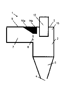
The basic construction of a cyclone 1 as is used for the separation of solids
or
liquids from a fluid stream is schematically shown in Fig. I a. The cyclone 1
according to the present invention of Fig. la comprises a cylindrical upper
hous-
ing part 2 and a conical lower housing part 3. The cylindrical housing part 2
and
the conical housing part 3 together form the housing 2, 3 of the cyclone 1,
i.e.
the cyclone housing 2, 3. The upper end of the cyclone housing 2, 3 is closed
with a housing cap 5. A dip tube or vortex finder 12 is inserted in a central
open-
ing of the housing cap 5 so that the dip tube 12 extends partially outside and
partially inside the cyclone housing 2, 3. A feed channel 7 is connected with
its
CA 03025587 2018-11-26
WO 2017/207606
PCT/EP2017/063113
12
first end with an inlet opening 6 in the cylindrical housing part 2 of the
cyclone 1.
With the second end the feed channel 7 may, for example, be connected with
the discharge opening of a blast furnace/a fluidized bed. The inlet opening 6
and
the feed channel 7 which is directly placed thereon are arranged at the upper
end of the cylindrical housing part 2. Preferably, in this case the upper wall
9 of
the feed channel 7 and the housing cap 5 are arranged in a coplanar manner.
Typically, the cyclone 1 is arranged such that the conical housing part 3 is
ori-
ented downwards into the direction of the gravitational field. At its lowest
point
the discharge port 4 is provided through which the particles and/or the liquid
which has been extracted from the fluid stream can be discharged.
During operation the fluid stream together with the particles is fed through
the
feed channel 7 and the inlet opening 6 into the housing part 2. This,
typically, is
effected in a tangential manner (cf. Fig. 1 b) so that a circular movement of
the
fluid stream is induced. The fluid stream moves on a helical path from the
inlet
opening 6 into the direction of the conical region 3. Due to the centrifugal
force
the particles are transported to the outer wall of the cyclone 1 and there, by
the
effect of gravitation, they move into the direction of the discharge port 4.
The
purified gas or, in the case of a hydrocyclone, the purified liquid exits the
cy-
clone 1 upwards through the dip tube 12.
In the case of the depicted embodiment in the feed channel 7 a first ramp 10a
and in the interior of the cyclone housing 2,3 a second ramp 11 a through
which
the fluid stream is diverted are provided. The first ramp 10 is arranged at
the
upper wall 9 of the feed channel 7 and has the shape of a wedge. The second
ramp 11 a is arranged at the housing cap 5 and has the same height as the
first
ramp 10a. The ramps 10a, 11 a are connected via a, for example cuboidal, con-
necting element 14, wherein between them, in particular, no gap or plat-
form/shoulder is provided.
CA 03025587 2018-11-26
WO 2017/207606
PCT/EP2017/063113
13
The first ramp 10a in the interior of the feed channel 7 extends along about
one
third of the length of the feed channel 7 and rests against the inner wall 8
of the
feed channel 7. The height of the ramp 10a is about 45 % of the height of the
feed channel 7 (based on the free inner cross-section of the feed channel 7).
The width of the ramp 10a is about 50 % of the width of the feed channel 7
(cf.
Fig. 1b), The first ramp 10a begins starting from the second end of the feed
channel 7 in the second half of the feed channel 7 and extends up to the first
end of the feed channel 7 at the inlet opening 6 of the cyclone housing 2, 3.
The
second ramp 11 a is arranged such that it rests against the outer wall 13 of
the
cylindrical housing part 2 of the cyclone 1. In addition, the ramp ha has a
curved design so that it is adjusted to the round shape of the outer wall 13
of the
cylindrical housing part 2 of the cyclone 1.
Fig. 1 c shows that both, the second ramp lla and also the first ramp 10a,
have
the shape of a wedge with an angle of slope of about 30 each, wherein the
height of the ramp lla increases into the direction of the inlet opening 6.
During operation a gas stream, for example from a blast furnace, together with
solid particles contained therein is fed into the feed channel 7. The gas
stream
flows along the feed channel 7 into the direction of the cyclone housing 2, 3
(in
the view of Fig. 1 a from the left side to the right side), and in the upper
region of
the feed channel 7 it is deflected downwards at the first ramp 10a so that it
enters the cylindrical housing part 2 in a distance to the housing cap 5 which
at
least corresponds to the height of the first ramp 10a. With this redirection
at the
first ramp 10a a part of the gas and some particles, in addition, are provided
with
a velocity component in downward direction which supports the transport of the
particles into the direction of the discharge port and prevents that the
particles
enter the low energy zone 15 in the upper region of the cyclone 1 near the
hous-
ing cap 5. With the tangential arrangement of the feed channel 7 in the cylin-
drical housing part 2 a circular movement is initiated which through the
centrifu-
CA 03025587 2018-11-26
WO 2017/207606
PCT/EP2017/063113
14
gal forces results in the separation of the particles from the gas stream.
Parti-
cles which nevertheless have entered the low energy zone 15 near the housing
cap 5 circulate around the dip tube 12. Due to the second ramp 11 a at the
hous-
ing cap 5 these particles are deflected downwards and so they enter a region
in
which the particles can efficiently be separated from the gas stream. Hence,
an
accumulation of particles in the low energy zone 15 is prevented. Then the gas
stream moves downwards, in large part on a helical path, into the conical hous-
ing part 3, wherein during the transport the particles are separated from the
gas
stream. Then, the purified gas stream exits the cyclone 1 through the dip tube
12.
The Fig. 2a to 2c show a second embodiment of the invention in views which
are equivalent to the figures la to 1 c. For the sake of simplicity in the
following
figures only the differences with respect to the first and/or the preceding
embod-
iments are described each. For the same elements the same reference signs
(optionally with indices a-f for the first to sixth embodiments) are used and
refer-
ence is made to their preceding description.
The embodiment of the Fig. 2a to 2c is characterized by an alternative arrange-
ment of the ramp. As can be seen in Fig. 2a, the first ramp 10b in the feed
channel 7 already reaches its maximum height before the inlet opening 6 of the
cyclone housing 2, 3. The ramp 10b extends in a, preferably cuboidal, section
16 with constant height up to the inlet opening 6. The length of the first
ramp
10b is about 60 % of the length of the feed channel 7. The second ramp lib
does not differ from the second ramp 11 a of the first embodiment of the Fig.
la
to 1 c.
In the case of the third embodiment of the Fig. 3a to 3c the ramp 10c extends
along the whole width of the feed channel 7 (cf. Fig. 3b). The characteristic
CA 03025587 2018-11-26
WO 2017/207606
PCT/EP2017/063113
profile of the height of the ramp 10c is identical with that of ramp 10b
according
to the embodiment of the Fig. 2a to 2c.
In the case of the fourth embodiment of the Fig. 4a to 4c the ramp 10d is char-
5 acterized by a particularly small design so that its width corresponds
only to one
third of the width of the feed channel 7. Apart from that, the ramp 10d has a
similar design as the ramp 10b according to the second embodiment.
In the case of the fifth embodiment of the Fig. 5a to 5c both, the ramp 10e
and
10 also the ramp 11e, have a design of a concave ramp. The concave ramps
10e,
11e do not have a constant slope, but a slope which increases into the
direction
of the inlet opening 6 in the housing 2, 3 each. Here, the lengths and the
widths
of the ramps 10, 11 correspond to those of the embodiment of the Fig. 1a to
1c.
15 In the case of the sixth embodiment of the Fig. 6a to 6c the cyclone 1
only com-
prises one ramp 10f in the feed channel 7, while the second ramp 11 at the
housing cap 5 was omitted.
In the case of the seventh embodiment of the Fig. 7a to 7c the cyclone 1 is
characterized by a geometric displacement between feed channel 7 and housing
cap 5. Accordingly, also the ramps 10g, 11g may be characterized by a geomet-
ric displacement to each other, which is a vertical displacement here.
It is a matter of course that the shown variants of the first and second ramps
10a-g, 11a-g according to the first to seventh embodiments can arbitrarily be
combined with each other.
CA 03025587 2018-11-26
WO 2017/207606
PCT/EP2017/063113
16
List of reference signs
1 cyclone
2 cylindrical housing part
3 conical housing part
4 discharge port
5 housing cap
6 inlet opening
7 feed channel
8 inner wall of the feed channel
9 upper wall of the feed channel
10a-g ramp in the feed channel
11a-e, g ramp in the housing
12 dip tube
13 outer wall of the housing
14a-e, g connecting element
15 low energy zone
16b-d, f, g cuboidal section