Note: Descriptions are shown in the official language in which they were submitted.
CA 03025959 2018-11-29
1 LID FOR AN ALUMINUM BEVERAGE CAN
2
3 FIELD
4
The invention refers to can lids for two-piece aluminum beverage cans, and
more
6 particularly to a two-piece aluminum beverage can with a unitary DWI can
body and
7 can lid with a pull tab.
8
9 BACKGROUND
11 .. Two-piece beverage cans comprise a can body made from one piece of
aluminum
12 sheet metal and a can lid with a pull tab affixed to the can lid. A
score line in a panel
13 of the can lid defines a tear panel that can be opened by means of the
pull tab. The
14 pull tab can be a stay-on-tab that opens a hinged tear panel. In prior
art cans, the
pull tab is affixed to the can end by a rivet that is formed from the sheet
metal of the
16 can lid. Can lids are also known as can ends.
17
18 The can body is a drawn and ironed (DWI: drawn and wall-ironed) can body
that is
19 produced by first drawing an aluminum blank into a cup and then ironing
the walls of
the cup to form the can body. The can body has an open end with a reduced
21 diameter. The reduced diameter of the can body's open end is achieved by
way of
22 .. necking the can body in a necking machine in which the diameter of the
open end is
23 reduced in several stages.
24
Prior art cans often have a body that is cylindrical along the largest portion
of its
26 longitudinal extension. A typical diameter of prior art aluminum
beverage cans is 66
27 .. mm. These cans are named 211 cans in the industry.
28
29 After filling of a can body e.g. with a carbonated beverage, a
respective can lid is
attached to the can body by way of a folded double seam. The can lid has a
smaller
31 diameter than the can body.
1
CA 03025959 2018-11-29
1
2 To match a respective can lid, the can body diameter at the can body's
open end is
3 reduced from 66 mm to the fitting diameter for the can lid, e.g. -57 mm
(206), 55 mm
4 (204), 52 mm (202) or 50 mm (200), by way of necking.
6 A typical can body has a base and a cylindrical side wall that extends
upwardly from
7 the base and that has a wall thickness in the order of 94 to 97 pm for a
can having a
8 diameter of 66 mm. A can having a diameter of 58 mm typically has a wall
thickness
9 in the order of 90 to 94 pm. The can body further has a tapering neck
that extends
upwardly from the cylindrical side wall and that defines the reduced diameter
open
11 end of the can body prior to seaming. The can body's open end has a
smallest
12 internal diameter called plug diameter, which approximately matches the
metrical
13 dimension of the can lid, e.g. 52 mm.
14
The ratio between the can maximum diameter and the plug diameter that is
16 achieved by way of necking is called necking ratio. The base includes a
standing
17 ring and a dome arranged within the standing ring.
18
19 The can lid is made from sheet metal aluminum and has a central panel
wherein the
rivet and the tear panel are arranged. The central panel is circumferentially
21 surrounded by a countersink that in turn is circumferentially surrounded
by an
22 upwardly extending leg, e.g. a chuck wall. At the outer end of the
upwardly
23 extending leg, a curl is arranged that eventually is folded to form the
seam that
24 connects can body and can lid and that defines the lid outside diameter.
The can
lid's chuck wall defines a plug diameter of the can lid.
26
27 On the central panel, a rivet for connecting a pull tab and a tear panel
defined by a
28 score line are arranged. The tear panel can be opened by means of the
pull tab that
29 breaks the score line when a handle part of the pull tab is lifted and
thus an opening
part of the pull tab is pressed on the tear panel next to the score line.
Between the
31 handle part and the opening part of the pull tab, a rivet island is
arranged that is
2
CA 03025959 2018-11-29
1 connected to the central panel by means of the rivet and that serves as a
bending
2 hinge for the pull tab.
3
4 SUMMARY
6 It is an object of the invention to provide a can lid for an improved two-
piece
7 aluminum beverage can.
8
9 According to the invention, this object is achieved by a can lid for an
aluminum
beverage can, said can lid comprising a pull tab, said can lid having a chuck
wall
11 defining a plug
12
13 diameter, a countersink and central panel having a panel radius. On the
central
14 panel, a score line defining a tear panel and a rivet for connecting a
pull-tab to the
can lid are arranged. The lid has a lid plug diameter of between 45 to 49 mm,
an
16 outside diameter of between 52 to 55 mm, and a weight of less than 1.9 g.
The
17 central panel has a thickness of less than 0.19 mm. The rivet is
arranged off-center
18 on the central panel. The rivet is tilted so that the rivet provides an
axis of rotation of
19 the pull tap that has an angle of between 1 and 6 with respect to an
axis vertical
that is vertical with respect to the central panel or at least one ramp-up
bead is
21 arranged on either side of pull tab or on both sides of the pull tab.
Thus, the rivet is
22 tilted with respect a normal to a plane defined by countersink and the
axis of rotation
23 defined by the rivet is tilted with respect a normal to a plane defined
by countersink.
24 The tilt of the rivet facilitates lifting of a handle part of the pull
tab if the pull tab is
rotated about the rivet.
26
27 Alternatively, both, the rivet is tilted and at least one ramp-up bead
is arranged on
28 either side of pull tab or on both sides of pull tab.
29
Preferably, the pull tab can be swiveled between an initial shelf position
wherein the
31 opening part of the pull tab faces away from the tear panel and an
opening position
3
CA 03025959 2018-11-29
1 wherein the opening part of the pull tab is arranged to touch the tear
panel, when the
2 handle part is lifted.
3
4 When the rivet is arranged off centre with respect to the central panel
the finger
access space for opening of the easy opening end can get too small. This
problem
6 can be solved by a rotation tab. Initially, in factory finished position
and when a
7 beverage can is stored in a shelf, the handle part of the tab is
positioned in line or
8 partly rotated to the centre line of the tear panel. Rotation of the tab
will now be
9 required in either direction to get the tab in the opening position, like
for standard
ends. Accordingly, the pull tab is initially not in the opening position
allowing opening
11 the tear panel and, therefore, first must be rotated from the initial
shelf position to the
12 opening position prior to opening the tear panel. Rotation of the pull
tab about the
13 tilted rivet not only results in an alignment of the pull tab with the
tear panel but also
14 results in a lifted handle part of the pull tab that thus can easier be
gripped. In
addition to a tilt of the rivet or as an alternative, at least one ramp-up
bead can be
16 provided that is arranged on either side or on both sides of the pull
tab. Such ramp
17 can also cause or support a lifting of the handle part if the pull tab
is rotated about
18 the axis of the rivet. Preferably, the ramp-up bead is arranged on the
central panel.
19
To accommodate this action, and to improve finger access, two different
approaches
21 are provided:
22
23 Two ramp-up beads are arranged on both sides of the tab to accommodate
bridging
24 the tab over the chime and elevating the edge to an easy finger access
level.
Optionally a tab-positioning bead underneath the tab is incorporated in the
central
26 panel or on the tab's side facing the central panel or both, which
accommodates
27 finding the accurate opening position at the end of the rotation.
28
29 Alternatively or additionally, a tilted rivet island is provided, which
from nature
provides a tab elevation during rotation to accommodate bridging the chime and
to
31 improve finger access. Again, optionally a tab positioning bead can be
provided,
4
CA 03025959 2018-11-29
1 which accommodates finding the accurate opening position at the end of
the
2 rotation.
3
4 .. One or more orientation beads can be provided that are configured and
arranged to
support aligning of the initially rotated pull tab into the opening position
suitable for
6 opening the tear panel. For instance, such orientation bead can be
configured to
7 provide a click-in effect when the pull is rotated about the rivet and
eventually
8 reaches its aligned orientation. The click-in effect providing the
tactile feedback can
9 be achieved by means of a gap or a recess in the orientation bead that
receives a
.. part of the pull tab, for in- stance a protrusion of the pull tab facing
the central panel,
11 when the pull tab is aligned with the tear panel.
12
13 Additionally or alternatively, the pull tab may have a gap or a recess
on the side
14 facing the central panel. This gap or recess may engage with the double
seam that
connects the can lid with the can body when the pull tab is aligned in its
opening
16 .. position, thus providing tactile feedback to the user indicating that
the pull tab is
17 positioned for opening the can.
18
19 .. Accordingly, in a preferred embodiment, the central panel comprises at
least one tab
positioning notch or recess that is arranged to provide a tactile feedback if
the tab is
21 swiveled in its opening position suitable for opening the tear panel.
The tab
22 .. positioning recess is provided on the tab's side facing the central
panel, the recess
23 being arranged to engage with the seam connecting the can lid to the can
body
24 when the can lid is applied to a can body.
26 .. The off-set of the axis of rotation of the rivet and the center of the
central panel is
27 prefer- ably between 3 and 15 mm and even more preferably between 4 and
8 mm,
28 e.g. 4.5 mm. This allows for large enough an opening even in a central
panel having
29 a smaller diameter than previous central panels.
5
CA 03025959 2018-11-29
1 Preferably, the axis of rotation of the pull tap that has an angle of
between 20 and 4 *
2 with respect to the axis vertical to the central panel. This provides for
enough of a lift
3 of the handle part of the pull tab when to pull tab is rotated in its
opening position to
4 pass the chime.
6 Preferably, two ramp-up beads are arranged on the central panel, one ramp-
up bead
7 .. on each side of the pull tab. Thus, a user can rotate the pull tab in
both directions
8 from the initial shelf position to the opening position, while either
ramp-up bead will
9 help to lift the handle part of the pull tab to pass the chime that is
provided by the
seam connecting the can lid to the can body after the can lid is applied to
the can
11 body.
12
13 Preferably, the central panel has a diameter of between 36 mm and 40 mm
and is
14 .. thus smaller than previous central panels. This allows for a smaller
overall size of
.. the can lid that in turn allows for lighter can lids an can bodies compared
to previous
16 cans having the same contents volume.
17
18 Preferably, the can end is made from aluminum or steel sheet metal, that
may be
19 pre- coated or plain.
21 Preferably, an absorption bead is arranged next to the tear panel.
22
23 BRIEF DESCRIPTION OF THE DRAWINGS
24
The above and other aspects, features and advantages of the present invention
will
26 be more apparent from the following more particular description thereof
presented in
27 conjunction with the following drawings, wherein:
28
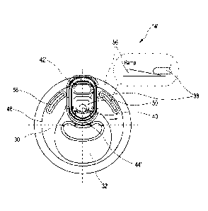
29 Figure 1 is a side-elevated perspective view of a seamed two-
piece beverage
can according to the invention;
31
6
CA 03025959 2018-11-29
Figure 2 is a cross-sectional view of a seamed two-piece beverage can
along
2 the can's longitudinal axis;
3
4 Figure 3 is a cross-sectional view of a can body prior to
seaming;
6 Figure 4 is a cross-sectional view of a can lid prior to
seaming;
7
8 Figure 5 is a top-level view of a first embodiment of a can lid
according to the
9 invention with the tab in its opening position;
11 Figure 6 is a cross-sectional view of an alternative can lid
prior to seaming;
12
13 Figure 7 is a top-level view of a second alternative embodiment
of a can lid
14 according to the invention with the tab in its shelf position;
16 Figure 8 is a top-level view of the second embodiment of a can
lid according to
17 Figure 7 with the tab in its opening position;
18
19 Figure 9 is a top-level view of a third alternative embodiment
of a can lid
according to the invention with the tab in its shelf position;
21
22 Figure 10 is a top-level view of the third embodiment of a can
lid according to
23 Figure 9 with the tab in its opening position;
24
Figure 11 shows details of an orientation notch on the lower side of the
handle
26 part of the pull tab that helps aligning the pull tab in its
opening
27 position;
28
29 Figure 12 shows details of a first alternative embodiment of a
score line; and
31 Figure 13 shows details of a second alternative embodiment of
the score line.
7
CA 03025959 2018-11-29
1
2 DETAILED DESCRIPTION
3
4 The following description is of the best mode presently contemplated for
carrying out
the invention. This description is not to be taken in a limiting sense but is
made
6 merely for the purpose of describing the general principles of the
invention. The
7 scope of the invention should be determined with reference to the claims.
8
9 Figure 1 shows a two-piece aluminum beverage can 10 according to the
invention.
The can comprises a can body 12 and a can lid 14 seamed to the can body. Can
11 body 12 is a unitary DWI (drawn wall-ironed) can body and can lid 14 has
a pull tab
12 38.
13
14 The can body 12 is formed from a single piece of sheet metal aluminum
(blank) and
has a base 16, a cylindrical sidewall 18 and a neck 20. The base 16 has a
standing
16 ring 22 and a dome 24. Can body 12 is preferably made from aluminum, in
particular
17 from series 3000 aluminum.
18
19 The can lid 14 has a chuck wall 26, a countersink 28 and a central panel
30. In the
central panel, a tear panel 32 is provided, which is defined by a score line
34. Next
21 to the tear 10 panel, a material absorption bead 36 is arranged. Pull
tab 38 is affixed
22 to the central panel 30 by means of a rivet 40. A central section of
pull tab 38 is a
23 rivet island 50 that is fixated to central panel 30 by means of rivet
40. Typically, pull
24 tab 38 can be rotated about rivet 40 if a certain force is applied. The
axis of rotation
is perpendicular with respect to a plane defined by rivet island 50. Pull tab
38 has a
26 handle part 42 to be gripped by a user's finger and an opening part 44
that is
27 pressed against the tear panel 32 if the handle part 42 is lifted by a
user. Thus, the
28 pull tab 38 serves to rupture the score line 34 in order to open the
beverage can 10
29 in a manner known per se. The tear panel 32 thus defines the dimensions of
the
opening created by lifting the handle part of the pull-tab 38. The tear panel
defines
8
CA 03025959 2018-11-29
1 an opening - for instance a drinking opening - having an area of between
300 mm2
2 to 350 mm2 after opening the beverage can.
3
4 Can lid 14 is fixed to can body 12 by means of a folded double seam 41.
Seam 41
has a diameter of between 46 mm and 49 mm.
6
7 The diameter L of the seam 41 is approximately 48 mm. The diameter J of
the stand
8 ring is smaller than the diameter L of the seam 41. Therefore, beverage
cans can be
9 stacked upon another, so that the stand ring of the upper can protrudes
into the
space within seam 41. Alternatively, the stand ring may have a larger diameter
than
11 the seam.
12
13 Can body 12 has a can body plug diameter of between 45 to 49 mm and a
weight
14 below 9.3 g for a 330 ml can, and below 9.7 g for a 355 ml can.
16 Can lid 14 has a can plug fitting diameter of between 45 to 49 mm, an
outside
17 diameter of between 52 to 55 mm, a central panel with a thickness of
less than 0.19
18 mm, e.g. 0.183 mm, and a weight of less than 1.9 g.
19
Fig. 2 is a cross-sectional view of can 10 with can lid 14 seamed to can body
12. In
21 the cross-sectional view, chuck wall 26 and countersink 28 of can lid 14
can be seen
22 as well as cylindrical side wall 18, neck 20, stand ring 22 and dome 24
of the can
23 body 12.
24
Can diameter A is between 56 mm and 59 mm, for instance approximately 58 mm.
26 Can diameter A corresponds to the diameter of cylindrical side wall 18.
As further
27 can be taken from Fig. 3, base 16 extends along a height F of about 5 to
10 mm.
28 Cylindrical side wall 18 has a height G of about 120 mm. Neck 20 has a
height H of
29 about 17 mm. Can body 12 is symmetric about a longitudinal axis 46.
Prior to
sealing, can body 12 has an upper open end with an inner diameter B, which is
31 called a plug diameter, and which is about 46 mm.
9
1
2 Can body 12 is produced by a draw and wall ironing process (DWI), wherein
first a
3 cup is formed and then the side wall is formed by drawing and wall
ironing.
4 Thereafter, neck 20 is formed in a necking machine (necker) to achieve an
upper
can end that has a smaller diameter than the maximum can diameter. The ratio
of
6 plug diameter B to can diameter A B/A is called necking ratio. The
necking ratio of
7 can body 12 of the embodiment of Fig. 3 is a little less than 80%.
8
9 Can body 12 is drawn from a single piece of aluminum sheet metal, having
a gauge
of 242 pm. Therefore, the wall thickness in the middle of dome 24 is
approximately
11 240 pm.
12
13 The maximum wall thickness of the can in the middle of the dome of the
base is
14 between 235 pm and 245 pm, such as 240 pm or 242 pm. The tool for
drawing and
wall ironing preferably is configured to create a transitional wall thickness
from the
16 base to the side wall in two steps. The tool preferably provides a first
step with an
17 angle of 10 and a second step with an angle of -30'. Thus, the wall
thickness of the
18 can body is reduced from about 240 pm in the area of the base to about
79 pm at
19 the middle part of side wall 18.
21 The wall thickness of the middle part of the neck is about 111 pm.
22 The neck has a flange (at its upper end) having a wall thickness
23 in the range of between 130 pm and 150 pm, for instance 140 pm.
24
26 The transition from side wall 18 to flange 20 is rounded. The radius in
27 the transition from side wall 18 to neck 20 is between 10 mm and 20 mm,
28 for instance 15 mm. Such a transition is also called a "round shoulder".
29
The angle of the neck relative to the side wall 18 of a central longitudinal
axis of can
31 body 12 is between 25 and 35 , for instance 30 .
Date Recue/Date Received 2020-09-17
1
2 Beverage can 10 has a nominal volume of between 330 ml and 355m1 and a
height
3 E of approximately of between 145 mm and 147 mm for a 330m1 can and a
height E
4 of between 156 mm and 159 mm for a 355 ml can.
6 A can body according to the embodiments of the Figures has a weight below
9.3 g
7 for a can with a nominal volume of 330 ml and below 9.7 g for a can having a
8 nominal volume of 355 ml.
9
The total internal volume of the seamed can is the nominal volume plus a head
11 space. The volume of the head space is little less than 20 ml, for
instance 18 ml.
12 Thus, a can with a nominal volume of 330 ml has a total internal volume
of 348 ml,
13 and a can with a nominal volume of 355 ml has a total internal volume of
373 ml.
14
Figure 4 is a cross-sectional view of can lid 14 prior to seaming,
illustrating the
16 outside diameter (curl diameter) K. Figure 4 further illustrates a can
lid plug diameter
17 R that is defined by chuck wall 26 and a central panel diameter Q of
central panel
18 30.
19
Figure 5 is a top-level view of a first embodiment of a can lid according to
the
21 invention. Can lid 14 as illustrated in Figure 5 has a can lid plug
diameter R of 45.4
22 mm, and central panel diameter Q of 37.55 mm. As can be taken from
Figure 5, on a
23 central panel 30, an off centre rivet 40 is arranged that connects a
rivet island 50 of
24 pull tab 38 to central panel 30. Rivet island 50 is an integral part of
pull tab 38 and
forms a bendable hinge between handle part 42 of pull tab 38 and an opening
part
26 44 of pull tab 38. An outer curl 54 of pull tab 38 provides for
sufficient stiffness
27 between handle part 42 and opening part 44, so that opening part 44 can
exert
28 strong enough a force on tear panel 32 when the handle part 42 of pull
tab 38 is
29 lifted. Tear panel 32 is defined by a score line 34 and has an area of
331 mm2 and
has a shark fin design featuring a triangular extension next to the rivet that
11
Date Recue/Date Received 2020-09-17
1 .. improves pouring becauseit eases entering air in the can. Can lid 14 is
made from
2 pre-coated aluminum sheet metal.
3
4 In order to improve the accessibility of handle part 42 of pull tab 38,
rivet 40 may be
.. tilted, as shown in Figure 6. The axis of rotation defined by rivet 40 is
tilted with
6 .. respect to a normal to a plane defined by countersink 28. Likewise, the
plane
7 defined by rivet island 50 has a tilt angle with respect to the plane
defined by
8 .. countersink 28. The tilt angle is between 2 and 4 , for instance 3 . A
tilted rivet as
9 shown in Figure 6 is particularly useful with an embodiment as shown in
Figure 5.
However, a tilted rivet can also be provided with an embodiment as shown in
11 .. Figures 7 and 8 or 9 and 10.
12
13 In the embodiment of Figure 5, pull tab 38 is already orientated in its
opening
14 position where the opening part 44 of pull tab 38 is placed above tear
panel 32.
Therefore, lifting handle part 42 of pull tab 38 causes opening part 44 to
cause a
16 force on tear panel 32 leading to a rupture of score line 34.
17
18 Alternatively, the can lid can have a pull tab that initially is
orientated in shelf-position
19 with respect to the tear panel. In such embodiment, the pull-tab first
must be aligned
.. with tear panel in order to allow opening of tear panel. Aligning of pull
tab requires a
21 .. rotation of the pull tab that can help to lift the handle part of the
pull tab so that the
22 handle part can be gripped easier.
23
24 .. Lifting and aligning of the handle part of pull tab can be facilitated
by ramp-up beads
arranged on either side of pull tab 38; see Figure 9. Ramp-up beads assist
lifting the
26 .. pull tab when the pull tab is rotated about an axis of rotation defined
by the rivet; see
27 .. the embodiments depicted in Figure 7 to 10.
28
29 Figure 7 is a top-level view of a second, alternative embodiment of can
lid 14'. Figure
7 depicts this second embodiment in a state, where pull tab 38' is orientated
in a
31 shelf position that is suitable for stacking cans for instance when
stored in a shelf.
12
Date Recue/Date Received 2020-09-17
CA 03025959 2018-11-29
1 Figure 8 depicts the same can lid with pull tab 38' in its opening
position. As can be
2 taken from Figures 7 and 8, pull tab 38 must be rotated by about 1800 in
order to
3 swivel pull tab 38' from the shelf position to the opening position.
Swiveling occurs
4 around the axis of rotation defined by rivet 40'. When pull tab 38 is in
its opening
position, the handle part 42' extends beyond the outer diameter of central
panel 30.
6 Accordingly, handle part 42' must be lifted in order to move handle part
42' over the
7 chime formed by double seam 41 when can lid 14' is applied to a can body
such as
8 can body 12 (see Figs. 1 and 2).
9
In order to facilitate lifting of handle part 42 of pull tab 38 during
rotation, two ramp-
11 up beads 56 are provided. The wedge-like shape of ramp-up beads 56
causes lifting
12 off handle part 42 when handle part 42 slides along ramp-up bead 56 when
rotated.
13 The lifting of handle part 42 and the extension of handle part 42 over
the outer
14 periphery of central panel 30' facilitates gripping of handle part 42'
with the finger of
a user when opening can lid 14'.
16
17 Additionally, a gap is provided between the most elevated parts of ramp-up
beads
18 56. The gap between the two ramp-up beads 56 has a width that approximately
19 corresponds to the width of pull tab 38. This has the effect, that pull
tab 38 will
slightly lock in the gap between ramp-up beads 56 and thus provides a tactile
21 feedback when pull tab 38 has arrived in its opening position. This
further facilitates
22 handling of can lid 14' by a user.
23
24 Aligning of pull tab 38 is assisted by a tab positioning notch or recess
58 that is
arranged to provide a tactile feedback if the tab 38 is swiveled in its
opening position
26 suitable for opening the tear panel. The tab positioning recess 58 is
provided on the
27 tab's side facing the central panel 30, the recess being arranged to
engage with the
28 seam 41 connecting the can lid 14 to the can body 12 when the can lid 14
is applied
29 to a can body 12. When tab 38 is swiveled in its opening position,
positioning recess
58 engages with the seam 41 as shown in the detail depicted in Figure 11.
31
13
CA 03025959 2018-11-29
1 Figures 9 and 10 show an embodiment similar to the embodiment of Figure 7
and 8
2 differing only in details and dimensions. The pull tab 38" of the
embodiment of Figure
3 10 has a gap or a recess 58 on the pull tab's side facing the central
panel. This gap
4 or recess 58 may engage with the double seam 41 that connects the can lid
14" with
the can body 12 when the pull tab 38" is aligned in its opening position, thus
6 providing tactile feedback to the user indicating that the pull tab is
positioned for
7 opening the can.
8
9 Figure 11 shows details of the orientation notch 58 on the lower side of
the handle
part 42 of the pull tab 38 that helps aligning the pull tab in its opening
position.
11
12 Figures 12 and 13 show cross-sections of alternative embodiments of
score line 34
13 or 34', respectively. In the embodiment shown in Figure 12, an anti-
fracture score 60
14 is provided that runs in parallel to score line 34. Anti-fracture score
60 has the effect
to lower the tensile stress near the deepest portion of score line 34 and thus
avoids
16 an unwanted fracture of the score line prior to intended opening of tear
panel 32. In
17 the alternative embodiment shown in Figure 13, a background penetration
62 is
18 provided that runs along score line 34. Similar to the anti-fracture
score 60 of Figure
19 12, background penetration 62 has the effect to lower the tensile stress
near the
deepest portion of score line 34 and thus avoids an unwanted fracture of the
score
21 line prior to intended opening of tear panel 32.
22
23 List of reference numerals
24
10 Can
26 12 Can body
27 14, 14' Can lid
28 16 Base
29 18 Side wall
20 Neck
31 22 Stand ring
14
1 24 Dome
2 26 Chuck wall
3 28 Countersink
4 30 Central panel
32 Tear panel
6 34, 34' Score line
7 36 Absorption bead
8 38, 38" Pull Tab
9 40, 40' Rivet
41 Double Seam
11 42,42' Handle part
12 44 Opening part
13 46 Longitudinal axis of the can body
14 48 Panel radius
50 Rivet island
16
17 54 Pull tab curl
18 56 Ramp-up bead
19 58 Recess
60 Anti-fracture score
21 62 Background penetration
22 A Maximum diameter
23 B Plug diameter
24 NB Necking Ratio
26
27 E Can height
28 F Base height
29 G Cylindrical sidewall height
H Neck height
31 J Stand ring diameter
Date Recue/Date Received 2020-09-17
1 K Curl diameter
2 L Seam diameter
3 Q Central panel diameter
4 R Can lid plug diameter
S Rivet offset
16
Date Recue/Date Received 2020-09-17