Note: Descriptions are shown in the official language in which they were submitted.
CA 03026030 2018-11-29
' 1
DESCRIPTION
Title of Invention
LASER PROCESSING DEVICE
Technical Field
This invention relates to a laser processing device
with a tubular member being interposed between a lens, which
is provided at an output opening for a laser beam, and an
article to be machined.
Background Art
In a laser processing device for performing laser
welding, laser cutting, and so forth, it is necessary to
prevent spatters and fumes which are generated from a
workpiece irradiated with a laser beam, from adhering to a
lens provided at a laser output opening. The lens here is a
generic name for a condensing lens, a protective glass which
protects optics, and so forth.
In Japanese Laid-Open Patent Publication No. 01-107994,
for example, a laser processing device with a substantially
tubular cross-jet gas injection unit interposed between a
lens and an article to be machined is proposed.
Specifically, the cross-jet gas injection unit has formed
therein a through path through which a laser beam passes,
and a discharge pipe that discharges cross-jet gas in a
direction intersecting a direction in which the laser beam
travels and a suction pipe that draws the cross-jet gas
thereinto are connected to the cross-jet gas injection unit.
By flowing the cross-jet gas in this manner, it is possible
to keep spatters and fumes from reaching the lens through
CA 03026030 2018-11-29
2 '
the through path, whereby adherence of the spatters and
fumes to the lens is avoided.
Summary of Invention
The flow velocity of the cross-jet gas flowing near the
discharge pipe and the suction pipe is, as a matter of
course, higher than that of ambient air. Due to such a flow
velocity difference between the cross-jet gas and ambient
air, ambient air is caught up therein, which sometimes
causes a secondary air current toward the lens in the
through path.
In this case, there is fear that the spatters and fumes
carried by the above-described air current traverse the flow
of the cross-jet gas and move to the lens side in the
through path, resulting in adherence of the spatters and
fumes to the lens. In particular, since the fumes are
formed of metallic vapors thermally rising from a workpiece
melted at high temperatures due to laser irradiation, and
the density thereof is low, the fumes easily move by being
carried by the above-described air current. Thus, even with
the circulated cross-jet gas, it is difficult to suitably
avoid the adherence of the fumes to the lens.
A main object of the present invention is to provide a
laser processing device that can effectively avoid adherence
of fumes to a lens.
An aspect of the present invention provides a laser
processing device including: a laser scanner having a lens
provided in an output opening for a laser beam; and a
tubular member having a through path, through which the
laser beam output through the lens passes, the through path
84953801
3
being formed on the center side in a radial direction thereof.
In an inner wall portion, which faces the through path, of the
tubular member, a tubular filter is provided, and the tubular
member discharges gas from the filter into the through path,
the through path has a cylindrical shape whose diameter is
constant in an axial direction thereof, an inner surface of the
filter occupies 50% or more of an inner surface of the inner
wall portion, and a cross-jet gas injection unit configured to
inject a cross-jet gas in a direction intersecting a traveling
direction of the laser beam is provided between an irradiation
target for the laser beam and the tubular member.
In the laser processing device according to the present
invention, in the output opening for the laser beam, a
condenser lens that condenses the laser beam, a protective
glass that protects optics, and so forth, are provided as the
lens. The laser beam output from the laser scanner through
this lens passes through the through path formed on the
radially center side of the tubular filter, which is provided
in the inner wall portion of the tubular member, and is shone
onto an article to be processed. That is, the tubular member
and the filter are provided between the article to be processed
and the lens such that the laser beam passes through the
through path.
The tubular member discharges gas into the through path
through the filter in a manner that the gas passes through the
filter from an outer surface side of the filter located on the
radially outward side, which is an upstream side, toward an
inner surface side thereof located on the radially center side,
which is a downstream side. The velocity difference of the gas
CA 3026030 2019-01-07
84953801
4
is evened out by resistance or the like caused when the gas
passes through the filter. Owing to this, the gas having a
reduced velocity difference between locations is discharged
into the through path. As a result, between the article to be
processed and the lens, a high-pressure layer in which,
although the pressure thereof is higher than that of the
outside air, the occurrence of a turbulent flow is prevented,
is formed. Even when such a high-pressure layer is formed in
the through path, an air current that draws in fumes toward the
lens beyond the high-pressure layer is not generated.
Moreover, it is possible to generate a gentle flow of the gas
directed from the high-pressure layer toward the article to be
processed.
Therefore, with this laser processing device, since the
above-described high-pressure layer can be formed between the
article to be processed and the lens, it is possible to prevent
fumes, which are generated from the article to be processed,
from moving across the high-pressure layer toward the lens.
This makes it possible to effectively avoid the adherence of
the fumes to the lens.
In the above-described laser processing device, it is
preferable that the filter is a sintered metallic filter
comprising a sintered body made of powder of copper. Such a
filter can be stably used because the filter itself can be
prevented from being deteriorated even when spatters or the
like come into contact therewith. That is, by using the
sintered metallic filter, it is possible to improve the
durability of the laser processing device and achieve easy
maintenance, for example.
CA 3026030 2019-01-07
84953801
In the above-described laser processing device, it is
preferable that the filter has a cylindrical shape whose
diameter is constant in an axial direction thereof. In this
case, the filter can be formed into a simple shape, which makes
5 it possible to reduce the production cost of the filter and
reduce the production cost of the laser processing device
accordingly. Moreover, since the diameter of the filter is
constant in an axial direction, it is possible to effectively
prevent variation in velocity of the gas, which is discharged
into the through path through the filter, from occurring in the
axial direction. This makes it possible to form the high-
pressure layer satisfactorily and avoid the adherence of the
fumes to the lens.
In the above-described laser processing device, it is
preferable that the filter is supplied with the gas via a
chamber formed between the filter and an inner surface of an
outer wall portion of the tubular member, and the gas is
supplied to the chamber from a gas supply pipe in a manner that
an inflow direction of the gas is oriented along at least part
of an outer surface of the filter. In this case, the gas is
supplied to the chamber so as to increase the internal pressure
thereof while avoiding a situation in which the direction of
inflow of the gas is perpendicular to the outer surface of the
filter. Owing thereto, the pressure difference of the gas is
evened out in the chamber, and then the gas is substantially
evenly supplied to the whole of the filter. As a result, it is
possible to form the high-pressure layer by more effectively
preventing variation in velocity of the gas, which is
discharged into the through path through the filter, and thus
CA 3026030 2019-01-07
. .
84953801
5a
it is possible to avoid the adherence of the fumes to the lens.
According to an embodiment, there is provided a laser
processing device comprising: a laser scanner having a lens
provided in an output opening for a laser beam; and a tubular
member having a through path, through which the laser beam
output through the lens passes, the through path being formed
on a center side in a radial direction thereof, wherein a
tubular filter is provided in an inner wall portion which faces
the through path, the tubular member discharges gas from the
filter into the through path, the through path has a
cylindrical shape whose diameter is constant in an axial
direction thereof, an inner surface of the filter occupies 50%
or more of an inner surface of the inner wall portion, and a
cross-jet gas injection unit configured to inject a cross-jet
gas in a direction intersecting a traveling direction of the
laser beam, the cross-jet gas injection unit being located
between an irradiation target for the laser beam and the
tubular member.
Brief Description of Drawings
FIG. 1 is a schematic overall side view of a laser
processing device according to the present invention;
FIG. 2 is a sectional view of main portions of the laser
processing device of FIG. 1;
FIG. 3 is a schematic perspective view of a tubular member
of the laser processing device of FIG. 1;
CA 3026030 2020-03-06
CA 03026030 2018-11-29
6
FIG. 4 is a schematic plan view of the tubular member
of FIG. 3; and
FIG. 5 is a schematic perspective view of a tubular
member of a laser processing device according to another
embodiment of the present invention.
Description of Embodiments
Preferred embodiments of a laser processing device
according to the present invention will be described in
detail with reference to the accompanying drawings.
The laser processing device according to the present
invention can be suitably used in a case where welding,
cutting, boring, or the like is performed on an article to
he processed, by irradiating the same with a laser beam. In
the present embodiment, as depicted in FIG. 1, an example in
which a laser processing device 10 welds flanges 14 of a set
of workpieces 12 serving as an article to be processed, in a
state where the flanges are placed in contact with each
other, will be described. However, the embodiment is not
particularly limited to this example.
The laser processing device 10 mainly includes, for
example, a laser scanner 18 that is supported at the tip of
an articulated robot 16, and a tubular member 22 that is
detachably attached to a laser output opening 20, which will
be described later, of the laser scanner 18. As the
articulated robot 16, it is possible to use a publicly known
articulated robot, for example, that can move the laser
scanner 18 along the flanges 14 of the workpieces 12
supported on a workbench 26 by clampers 24 and move the
laser scanner 18 closer to or away from the workpieces 12.
CA 03026030 2018-11-29
7
Thus, explanation of the specific configuration of the
articulated robot 16 will be omitted.
The laser scanner 18 has a scanner main body 28
optically connected to a laser oscillator (which is not
depicted in the drawing), and, in the scanner main body 28,
optical members such as a mirror 30, a condenser lens (which
is not depicted in the drawing), and the like are housed.
Moreover, the laser output opening 20 is provided in the
scanner main body 28 as an opening for outputting a laser
beam LB that is emitted from the laser oscillator and then
deflected by the optical members, and a protective glass 32
(a lens) is detachably attached so as to cover the laser
output opening 20. That is, the laser scanner 18 outputs
the laser beam LB from the laser output opening 20 through
the protective glass 32.
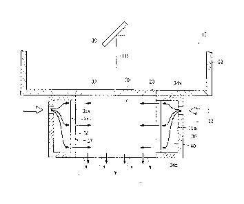
As depicted in FIG. 2, the tubular member 22 has ring-
shaped end face portions (a base end face portion 34a and a
front end face portion 34b), each having an inside diameter
which is substantially equal to or greater than the size of
the laser output opening 20, and a tubular cuter wall
portion 36 whose diameter is substantially equal to the
outside diameter of the end face portions 34a and 34b. It
is preferable that the end face portions 34a, 34b and the
outer wall portion 36 are integrally formed of a relatively
lightweight material such as aluminum.
In the tubular member 22, a tubular inner wall portion
37 whose inside diameter is substantially equal to the
inside diameter of the end face portions 34a, 34b and whose
diameter is smaller than the outside diameter of the end
face portions 34a, 34b, for example, is provided so as to be
CA 03026030 2018-11-29
8
substantially coaxial with the outer wall portion 36. In
the entire perimeter of this inner wall portion 37, a
tubular filter 38 is provided. It is preferable that an
inner surface 38a of the filter 38 occupies 50% or more of
the inner surface of the inner wall portion 37. Moreover,
it is preferable that an outer surface 38b of the filter 38
occupies 50% or more of the outer surface of the inner wall
portion 37. The reason therefor will be described later.
The tubular member 22 is attached near the laser output
opening 20 of the laser scanner 18 so that a through path
39, through which the laser beam LB output from the laser
output opening 20 passes, is formed on the center side of
the filter 38 in a radial direction. The inside diameter of
the filter 38 is not limited to the above-described size and
only has to be a size that allows the laser beam LB to pass
through the through path 39 without being interrupted by the
filter 38.
Moreover, a chamber 40 is formed between an inner
surface 36a of the outer wall portion 36 and the outer
surface 38b of the filter 38 facing the inner surface 36a.
That is, the chamber 40 is defined by the outer wall portion
36, the inner wall portion 37, and the end face portions 34a
and 34h. As depicted in FIGS. 3 and 4, gas is supplied from
a gas supply source (which is not depicted in the drawing)
to this chamber 40 via a gas supply pipe 42 connected to the
outer wall portion 36. For the purpose of illustration, in
FIGS. 1 and 2, the gas supply pipe 42 is not depicted in the
drawings. In this case, it is preferable that a direction
in which the gas supply pipe 42 extends into the chamber 40
is adjusted so that an inflow direction of the gas in which
CA 03026030 2018-11-29
9
the gas is supplied to the chamber 40 is oriented along at
least part of the outer surface 38b of the filter 38, in
other words, the inflow direction is not perpendicular to
the outer surface 38b. The reason therefor will be
described later.
In the present embodiment, as depicted in FIGS. 3 and
4, two gas supply pipes 42 are connected to the outer wall
portion 36 of the tubular member 22, and a direction in
which each gas supply pipe 42 extends is adjusted so as to
be inclined with respect to the radial direction of the
filter 38. Moreover, the relationship between the
directions in which the gas supply pipes 42 extend is set so
that the gas supplied by one of the two gas supply pipes 42
and the gas supplied by the other flow in the same direction
along the circumferential direction of the chamber 40 as
indicated by arrows in FIG. 4.
As the type of gas, for example, plant air or the like
can be suitably used because the plant air can be easily
supplied by using a simple configuration; however, the type
of gas is not particularly limited thereto. Any gas can be
used, and gas can be selected from among various gases in
accordance with the material of the workpieces 12, the use
of the laser processing device 10, and so forth.
The filter 38 is supplied with the gas via the chamber
40 from the outer surface 38b side. In this configuration,
gas passes through the filter 38 from the outer surface 38b
side being an upstream side toward the inner surface 38a
side being a downstream side, and the gas is then discharged
into the through path 39. The material, thickness, pore
size, and so forth, of the filter 38 may be optionally set
CA 03026030 2018-11-29
as long as, when gas is discharged through the filter 38
into the through path 39, the filter 38 allows the gas to
flow uniformly by evening out the velocity difference
between locations due to resistance or the like caused when
5 the gas passes through the filter 38.
Examples of the material of such a filter 38 include
sintered metal, ceramics, and resin; however, sintered metal
is preferable from the following viewpoint. That is, the
filter 38 (a sintered metallic filter) formed of sintered
10 metal is a porous body which is obtained by sintering metal
powder of copper, stainless steel, or the like. Such a
filter 38 can be stably used because the filter 38 itself
can be prevented from being deteriorated even when spatters
or the like come into contact therewith. Therefore, by
using the filter 38 formed of sintered metal, it is possible
to improve the durability of the laser processing device 10
and achieve easy maintenance, for example.
Moreover, the shape of the filter 38 is not limited to
a particular shape as long as the shape is tubular; however,
it is preferable that the filter 38 has a cylindrical shape
whose diameter is constant in an axial direction. In this
case, the filter 38 can be formed into a simple shape, which
makes it possible to reduce the production cost of the
filter 38 and reduce the production cost of the laser
processing device 10 accordingly. Furthermore, since the
diameter of the filter 38 is constant in an axial direction,
it is possible to effectively prevent variation in velocity
of the gas, which is discharged into the through path 39
through the filter 38, from occurring in the axial
direction.
. .
84953801
11
In addition, concerning the filter 38, it is desirable to
choose a filter having the finest possible degree of filtration
accuracy in order to achieve a laminar flow by decreasing the
Reynolds number by reducing a discharge speed; in the present
embodiment, a filter having the filtration accuracy of
approximately 5 m is used.
The laser processing device 10 may include a cross-jet gas
injection unit 60 as similarly described in Japanese Laid-Open
Patent Publication No. 01-107994 mentioned above, for example,
between the workpieces 12 and the tubular member 22. In this
case, the laser beam LB that has passed through the through
path 39 of the filter 38 further passes through the inside of
cross-jet gas, and the workpieces 12 is irradiated with the
laser beam LB. That is, by a discharge pipe 61 and a suction
pipe 62 which are connected to the cross-jet gas injection unit
60, the cross-jet gas is injected in a direction intersecting a
direction in which the laser beam LB travels.
The laser processing device 10 according to the present
embodiment is basically constructed as described above; next,
the workings and effects thereof will be described in
connection with an operation of performing laser welding by
using the laser processing device 10. In the following
description, a case where the laser processing device 10
includes the cross-jet gas injection unit will be described.
In laser welding using the laser processing device 10, as
depicted in FIG. 1, first, the laser scanner 18 is moved by the
articulated robot 16, and the laser output opening 20 is
disposed so that the laser beam LB can be shone onto a
CA 3026030 2020-03-06
84953801
12
welded portion of the workpieces 12.
Next, the laser beam LB is emitted from the above-
described laser oscillator in a state in which the gas is
supplied to the chamber 40 of the tubular member 22 from the
above-described gas supply source via the gas supply pipes 42
and the cross-jet gas is made to flow between the discharge
pipe and the suction pipe of the above-described cross-jet gas
injection unit.
In the tubular member 22, as a result of the directions in
which the gas supply pipes 42 extend being adjusted in the
above-described manner, as depicted in FIGS. 2 and 4, the gas
is supplied to the chamber 40 while avoiding a situation where
the gas inflow direction is perpendicular to the outer surface
38b of the filter 38, in other words, while avoiding a
situation where the gas is perpendicularly injected to the
filter 38. This evens out a pressure difference in the chamber
40 and thereby causes the gas to be substantially evenly
supplied to the whole of the filter 38. As a result, it is
possible to effectively prevent variation in velocity of the
gas, which is discharged to the through path 39 through the
filter 38, and it is possible to satisfactorily form, in the
through path 39, a high-pressure layer in which, although the
pressure thereof is higher than that of the outside air, the
occurrence of a turbulent flow is prevented. As depicted in
FIG. 2, a gentle flow of the gas directed toward the workpieces
12 can be generated from this high-pressure layer.
In this way, when the tubular member 22 discharges the
gas into the through path 39 through the filter 38, the
outer surface 38b of the filter 38 serves as a gas suction
CA 3026030 2019-01-07
CA 03026030 2018-11-29
13
surface and the inner surface 38a serves as a gas discharge
surface. Thus, by making the outer surface 38b of the
filter 38 occupy 50% or more of the outer surface of the
inner wall portion 37 as described above, the gas can be
taken in from a wide area of the inner wall portion 37.
Moreover, by making the inner surface 38a of the filter 38
occupy 50% or more of the inner surface of the inner wall
portion 37, the gas whose flow velocity has been decreased
can be discharged from a wide area in high volume. As a
result, it is possible to fill the through path 39 with the
gas whose pressure is slightly higher than that of ambient
air, which makes it possible to prevent ambient air from
being caught up therein, and more satisfactorily form the
high-pressure layer in which the occurrence of a turbulent
flow is prevented.
Furthermore, the laser scanner 18 outputs, from the
laser output opening 20 through the protective glass 32, the
laser beam LB guided from the laser oscillator to the
optical members in the scanner main body 28. After passing
through the through path 39 of the filter 38 provided in the
tubular member 22, the laser beam LB passes through the
above-described cross-jet gas and is shone onto the welded
portion of the workpieces 12.
In this way, by moving the scanner main body 28 along
the welded portion by the articulated robot 16 while welding
the spot of the workpieces 12 irradiated with the laser beam
LB, it is possible to perform laser welding on the entire
welded portion of the workpieces 12. At the time of this
laser welding, first, the cross-jet gas keeps spatters and
fumes generated from the workpieces 12 from moving toward
84953801
14
the protective glass 32. In particular, the movement of the
spatters, whose density is higher than that of the fumes, can
be effectively avoided by the cross-jet gas.
Moreover, even when a secondary air current is generated
by flow of the cross-jet gas whose flow velocity greatly
differs from that of ambient air and the fumes are caught up in
the air current, the movement of the fumes toward the
protective glass 32 of the through path 39 can be effectively
prevented. The reason is as follows: the above-described high-
pressure layer is formed between the cross-jet gas injection
unit and the protective glass 32, which makes it possible to
avoid the fumes from passing through the high-pressure layer.
That is, even when the high-pressure layer, in which the
occurrence of a turbulent flow is prevented, is formed in the
through path 39 as described above, a secondary air current
that draws the fumes into the high-pressure layer toward the
protective glass 32 is not generated. Moreover, as depicted in
FIG. 2, it is possible to guide the fumes to a side remote from
the protective glass 32 by a gentle flow of the gas directed
toward the workpieces 12 from the high-pressure layer. In
FIG. 2, the flow of the gas is indicated by solid arrows and
the flow of an air current containing the fumes is indicated by
dashed arrows.
As described above, with this laser processing device 10,
it is possible to effectively avoid the adherence of spatters
and fumes, which are generated from the workpieces 12 at the
time of laser welding, to the protective glass 32.
The present invention is not particularly limited to
the above-described embodiment, and various modifications
CA 3026030 2019-01-07
CA 03026030 2018-11-29
' 15 =
are possible within the scope of the present invention.
In the laser processing device 10 according to the
above-described embodiment, the two gas supply pipes 42 are
connected to the outer wall portion 36 of the tubular member
22, and a direction in which each gas supply pipe 42 extends
is adjusted so as to be inclined with respect to the radial
direction of the filter 38. However, the number of gas
supply pipes 42 is not limited to two, and the number of gas
supply pipes 42 may be one, or three or more.
Moreover, the gas supply pipes 42 may be connected to
both or one of the end face portions 34a and 34b, in place
of the outer wall portion 36 of the tubular member 22. For
instance, FIG. 5 shows a perspective view of the tubular
member 22 with two gas supply pipes 50 being connected to
the base end face portion 34a. Of constituent elements in
FIG. 5, constituent elements that have functions and effects
which are the same as or similar to those of the constituent
elements depicted in FIGS. 1 to 4 will be denoted by the
same reference characters, and detailed explanations thereof
will be omitted.
In this case, as depicted in FIG. 5, it is preferable
that a direction in which each gas supply pipe 50 extends is
inclined with respect to the axial direction of the tubular
member 22. Moreover, it is preferable that the relationship
between the directions in which the gas supply pipes 50
extend is set so that the gas supplied by one of the two gas
supply pipes 50 and the gas supplied by the other flow in
the same direction along the circumferential direction of
the chamber 40. By doing so, it is possible to supply, to
the filter 38, the gas whose velocity distribution is made
CA 03026030 2018-11-29
16
satisfactorily uniform in the chamber 40, with the inflow
direction of the gas to the chamber 40 being oriented along
at least part of the outer surface 38b of the filter 38.
Therefore, it is possible to satisfactorily form a high-
pressure layer, in which the occurrence of a turbulent flow
is prevented, by effectively preventing variation in
velocity of the gas discharged into the through path 39
through the filter 38, whereby it is possible to effectively
prevent fumes from adhering to the protective glass 32.
Moreover, in the laser processing device 10 according
to the above-described embodiment, the chamber 40 is formed
between the inner surface 36a of the outer wall portion 36
of the tubular member 22 and the outer surface 38b of the
filter 38 and the gas is supplied to the filter 38 via the
chamber 40. However, if the above-described high-pressure
layer can be formed in the through path 39, the gas may be
supplied to the filter 38 without passing through the
chamber 40.
Furthermore, in the laser processing device 10
according to the above-described embodiment, the tubular
member 22 is detachably attached near the laser output
opening 20 of the laser scanner 18 with the protective glass
32. However, the tubular member 22 may be detachably
attached near the laser output opening 20 of the laser
scanner 18 with no protective glass 32. In this case, it is
possible to effectively prevent fumes and spatters from
adhering to a condenser lens or the like.