Note: Descriptions are shown in the official language in which they were submitted.
GG12518/18G-P0529-CA
- 1 -
DESCRIPTION
STEERING DEVICE
TECHNICAL FIELD
[0001] The present invention relates to a steering device.
BACKGROUND ART
[0002] JP2013-141969A describes a steering device provided in an engine
compartment of a vehicle to apply a steering assist force to a turning wheel.
In this steering device, mount bracket portions for mounting a rack tube on
the side of a vehicle body are provided on both ends of the rack tube.
SUMMARY OF INVENTION
[0003] However, since a pair of the mount bracket portions are provided at
positions symmetrical with respect to a center axis of the rack tube in the
steering device described in JP2013-141969A, a part where the mount
bracket portions are provided has a large width (external dimension in a
direction perpendicular to the center axis of the rack tube). Thus, there is a
problem of poor workability in mounting the steering device on the vehicle
body. For example, if the rack tube has to be passed through an opening
provided in a vehicle body frame, the mount bracket portions cannot be
inserted into the opening depending on the size of the opening and it may not
be possible to mount the steering device.
[0004] The present invention aims to provide a steering device excellent in
mountability on a vehicle body.
[0005] According to one aspect of the present invention, a steering device,
includes: a rack shaft configured to turn wheels; a rack housing portion
housing the rack shaft; a pinion gear provided on one end side of the rack
CA 3026552 2018-12-05
. ,
_
% - 2 -
housing portion, the pinion gear being configured to transmit a rotational
force to the rack shaft; a first supporting portion provided on the rack
housing portion, the first supporting portion being configured to support the
one end side of the rack housing portion; and a second supporting portion
provided on the rack housing portion, the second supporting portion being
configured to support the other end side of the rack housing portion, wherein
the second supporting portion includes a first vehicle body mounting portion
and a second vehicle body mounting portion provided to project outwardly of
the rack housing portion, the first and second vehicle body mounting portion
being mounted on a vehicle body; and the first and second vehicle body
mounting portions are arranged to be shifted in an axial direction of the rack
housing portion so as not to overlap in the axial direction.
BRIEF DESCRIPTION OF DRAWINGS
[0006] FIG. 1 is a configuration diagram of an electric power
steering
device according to an embodiment of the present invention,
FIG. 2 is a plan view of the electric power steering device according to
the embodiment of the present invention,
FIG. 3 is a cross-sectional view of a second supporting portion along line
III-III of FIG. 2,
FIG. 4A is a view showing a procedure of positioning the electric power
steering device,
FIG. 4B is a view showing a procedure of inserting a right end side of the
electric power steering device through an opening of a side plate,
FIG. 4C is a view showing a procedure of inserting a second small bolt
mounting portion through the opening of the side plate,
FIG. 4D is a view showing a procedure of rotating the electric power
steering device,
CA 3026552 2018-12-05
- 3 -
FIG. 4E is a view showing a procedure of inserting a left end side of the
electric power steering device through an opening of a side plate,
FIG. 5A is a partial enlarged view showing a state where a first small
bolt mounting portion is located in the opening,
FIG. 5B is a partial enlarged view showing a state before the second
small bolt mounting portion is inserted into the opening after the first small
bolt mounting portion is inserted through the opening,
FIG. 5C is a partial enlarged view showing a state where the second
small bolt mounting portion is located in the opening,
FIG. 6A is a cross-sectional view of the electric power steering device
along line Vla-Vla of FIG. 5A,
FIG. 6B is a cross-sectional view of the electric power steering device
along line Vlb-Vlb of FIG. 5B,
FIG. 7 is a view showing an electric power steering device according to
Comparative Example 1 of the embodiment,
FIG. 8A is a partial enlarged view showing a state after a first small bolt
mounting portion is inserted through the opening,
FIG. 8B is a partial enlarged view showing a first forward moving
process of moving the electric power steering device to a front side of the
vehicle body,
FIG. 8C is a partial enlarged view showing a rightward moving process of
moving the electric power steering device to a right side of the vehicle body,
FIG. 8D is a partial enlarged view showing a second forward moving
process of moving the electric power steering device to the front side of the
vehicle body,
FIG. 9A is a cross-sectional view of an electric power steering device
according to Modification 1-1 of the embodiment of the present invention,
FIG. 9B is a cross-sectional view of an electric power steering device
CA 3026552 2018-12-05
- 4 -
according to Modification 1-2 of the embodiment of the present invention, and
FIG. 10 is a cross-sectional view of an electric power steering device
according to Modification 2 of the embodiment of the present invention.
DESCRIPTION OF EMBODIMENT
[0007] An embodiment of the present invention is described with reference
to the drawings.
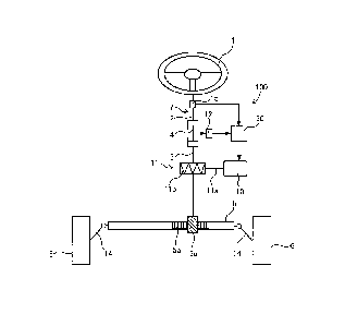
[0008] FIG. 1 is a configuration diagram of an electric power steering
device according to the embodiment of the present invention. As shown in
FIG. 1, the electric power steering device (hereinafter, written as steering
device) 100 includes an input shaft 2 configured to rotate as a driver
operates
a steering wheel 1, an output shaft 3 linked to a rack shaft 5 for turning
wheels 6 and a torsion bar 4 coupling the input shaft 2 and the output shaft
3. A steering shaft 7 is constituted by the input shaft 2, the output shaft 3
and the torsion bar 4.
[0009] The output shaft 3 is formed with a pinion gear 3a meshed with a
rack gear 5a formed on the rack shaft 5 to transmit a rotational force to the
rack shaft 5. When the steering wheel 1 is operated, the steering shaft 7
rotates, the rotation thereof is translated into a linear motion of the rack
shaft
by the pinion gear 3a and the rack gear 5a, and the wheels 6 are turned via
tie rods 14.
10010] The steering device 100 further includes an electric motor 10
serving as a power source for assisting the operation of the steering wheel 1
by the driver, a speed reducer 11 for decelerating and transmitting the
rotation of the electric motor 10 to the steering shaft 7, a torque sensor 12
for
detecting a torque acting on the torsion bar 4 by the relative rotation of the
input shaft 2 and the output shaft 3 according to the steering operation by
the driver, and a controller 30 for controlling the drive of the electric
motor 10
CA 3026552 2018-12-05
. - 5 -
on the basis of a detection result of the torque sensor 12.
[0011] The electric motor 10 is a brushed motor. The speed
reducer 11
includes a worm shaft 11 a coupled to an output shaft of the electric motor 10
and a worm wheel 1 lb coupled to the output shaft 3 and meshed with the
worm shaft 1 la. A torque output by the electric motor 10 is transmitted from
the worm shaft 1 la to the worm wheel 1 lb and applied as a steering assist
torque to the output shaft 3.
[0012] A steering torque applied to the input shaft 2 according
to the
steering operation by the driver is detected by the torque sensor 12, and the
torque sensor 12 outputs a voltage signal corresponding to that steering
torque to the controller 30. The controller 30 calculates the torque output by
the electric motor 10 on the basis of the voltage signal from the torque
sensor
12 and controls the drive of the electric motor 10 so that the calculated
torque is generated. In this way, the steering device 100 detects the steering
torque applied to the input shaft 2 by the torque sensor 12 and assists the
steering operation of the driver by controlling the drive of the electric
motor
on the basis of the detection result by the controller 30.
[0013] The controller 30 controls the drive of the electric motor
10 in
consideration of a steering angle detected by a steering angle sensor 15 in
addition to the steering torque. When the electric motor 10 is driven, a
rotational force of the electric motor 10 is transmitted to the rack shaft 5
via
the speed reducer 11 and the pinion gear 3a.
[0014] A housing 150 of the steering device 100 is described with
reference to FIG. 2. It should be noted that front-rear and lateral directions
of the steering device 10 are specified in accordance with front-rear and
lateral directions of a vehicle body as shown for the convenience of
description. The front-rear and lateral directions of the vehicle body are
directions parallel to a horizontal direction perpendicular to a vertical
CA 3026552 2018-12-05
. i
- 6 - direction. FIG. 2 is a plan view of the steering device 100 according to
the
,
embodiment of the present invention. In FIG. 2, side plates 9a, 9b
constituting parts of a vehicle body frame and mounting seats Ml, M2, M3
and M4 of the steering device 100 are shown by chain double-dashed line.
[0015] The housing 150 includes a rack housing 151 serving as a
rack
housing portion for housing the rack shaft 5 (see FIG. 1) extending straight
along the lateral direction of the vehicle body, a motor housing 158 for
housing the electric motor 10 (see FIG. 1) and a gear housing 159 for housing
the speed reducer 11 and the pinion gear 3a (see FIG. 1). It should be noted
that a direction parallel to a center axis 0 of the rack shaft 5 is called an
axial
direction. Since the rack shaft 5 and the rack housing 151 are concentric,
the center axis 0 is also a center axis of the rack housing 151.
[0016] The rack housing 151 is formed into a hollow cylindrical
shape
open on both axial ends. The rack shaft 5 is passed through the rack
housing 151 and both end parts thereof project from the both axial ends of
the rack housing 151. The both end parts of the rack shaft 5 are connected
to the tie rods 14. That is, the both end parts of the rack shaft 5 are
respectively coupled to the wheels 6 on right and left sides via the tie rods
14.
Connecting portions the rack shaft 5 with the tie rods 14 are covered by
steering rack boots 40.
[0017] The gear housing 159 is mounted on one axial end side of
the rack
housing 151, and the motor housing 158 is mounted on the gear housing
159. It should be noted that the one axial end side of the rack housing 151
means a left side from a lateral center of the rack housing 151, and the other
axial end side of the rack housing 151 means a right side from the lateral
center of the rack housing 151.
[0018] A first supporting portion 110 for supporting the one
axial end side
of the rack housing 151 is provided on the one axial end side of the rack
CA 3026552 2018-12-05
- 7 -
housing 151. A second supporting portion 120 for supporting the other axial
,
end side of the rack housing 151 is provided on the other axial end side of
the
rack housing 151. The first and second supporting portions 110, 120 are
mounted on the mounting seats Ml, M2, M3 and M4 of the vehicle body
frame by bolts and nuts. In this way, the steering device 100 is supported on
both ends on the vehicle body.
[0019] The first supporting portion 110 includes a first large
bolt
mounting portion 111A serving as a vehicle body mounting portion to be
mounted on the mounting seat M1 of the vehicle body frame and a second
large bolt mounting portion 111B serving as a vehicle body mounting portion
to be mounted on the mounting seat M2 of the vehicle body frame. The first
and second large bolt mounting portions 111A, 111B are formed at both right
and left sides of the gear housing 159 across the gear housing 159. The first
large bolt mounting portion 111A is provided to project toward an outer front
side of the rack housing 151, and the second large bolt mounting portion
111B is provided to project toward an outer rear side of the rack housing 151.
Specifically, the first and second large bolt mounting portions 111A, 111B
project in directions opposite to each other.
[0020] The first large bolt mounting portion 111A is arranged
on a side
closer to the left end of the rack housing 151 than the gear housing 159, i.e.
on an axially outer side. The second large bolt mounting portion 111B is
arranged on a side closer to the lateral center of the rack housing 151 than
the gear housing 159, i.e. on an axially inner side. Since each of the first
and
second large bolt mounting portions 111A, 111B has a similar hollow
cylindrical shape, the both are also collectively written as large bolt
mounting
portions 111 below.
[0021] The second supporting portion 120 includes a first small
bolt
mounting portion 121A serving as a first vehicle body mounting portion to be
I
CA 3026552 2018-12-05
- 8 -
mounted on the mounting seat M3 of the vehicle body frame and a second
.=
small bolt mounting portion 121B serving as a second vehicle body mounting
portion to be mounted on the mounting seat M4 of the vehicle body frame.
The first and second small bolt mounting portions 121A, 121B respectively
project in different directions. The first small bolt mounting portion 121A is
provided to project toward the outer front side of the rack housing 151, and
the second small bolt mounting portion 121B is provided to project toward
the outer rear side of the rack housing 151. That is, the second supporting
portion 120 is formed such that a projecting direction of the first small bolt
mounting portion 121A and that of the second small bolt mounting portion
121B do not coincide. In the present embodiment, the first and second small
bolt mounting portions 121A, 121B project in directions opposite to each
other.
[0022]
The first small bolt mounting portion 121A is arranged on a side
closer to the right end of the rack housing 151 than the second small bolt
mounting portion 121B, i.e. on an axially outer side. In other words, the
second small bolt mounting portion 121B is arranged on a side closer to the
lateral center of the rack housing 151 than the first small bolt mounting
portion 121A, i.e. on an axially inner side. Since each of the first and
second
small bolt mounting portions 121A, 121B has a similar shape, the both are
also collectively written as small bolt mounting portions 121 below.
[0023]
FIG. 3 is a cross-sectional view of the second supporting portion
120 along line
of FIG. 2. For the convenience of description, the vertical
and front-rear directions of the steering device 100 are defined as shown.
[0024]
As shown in FIGS. 2 and 3, the small bolt mounting portions 121
are provided with bolt mounting holes 123 into which bolts are to be
mounted. The bolt mounting holes 123 vertically extend at positions
separated by a predetermined distance XS1 from the center axis 0 of the rack
CA 3026552 2018-12-05
- 9 -
shaft 5 in the front-rear direction.
[0025] An outermost side part 129 of the small bolt mounting portion 121
in a front-to-rear width direction, i.e. a part most distant from the center
axis
0 of the rack shaft 5 in the front-rear direction, is a flat surface part
parallel
to the center axis 0 of the rack shaft 5. A pair of front and rear outermost
side parts 129 of the small bolt mounting portions 121 are provided parallel
to each other. A vertical dimension (height) of the small bolt mounting
portion 121 is larger than an outer diameter of the rack housing 151. A lower
end part of the small bolt mounting portion 121 has a substantially hollow
cylindrical shape and projects further downward than the lower end surface
of the rack housing 151.
[0026] A front-to-rear dimension XS2 from the center axis 0 of the rack
shaft 5 to the outermost side part 129 is longer than the distance XS1 from
the center axis 0 of the rack shaft 5 to a center axis of the bolt mounting
hole
123 (XS2 > XS1).
[0027] As shown in FIG. 2, the first and second small bolt mounting
portions 121A, 121B are arranged to be shifted in the axial direction of the
rack shaft 5. A shift amount in the axial direction is so set that the
outermost side part 129 of the first small bolt mounting portion 121A in the
front-to-rear width direction and the outermost side part 129 of the second
small bolt mounting portion 121B in the front-to-rear width direction do not
overlap in the axial direction of the rack housing 151.
[0028] In the present embodiment, the shift amount in the axial direction
is so set that the entire first small bolt mounting portion 121A and the
entire
small bolt mounting portion 121B do not overlap in the axial direction of the
rack housing 151. In other words, it means that the other small bolt
mounting portion 121 is not present on a cut virtual plane when one small
bolt mounting portion 121 is cut at an arbitrary position along the virtual
CA 3026552 2018-12-05
. - 10 -
plane perpendicular to the center axis 0 of the rack shaft 5.
,
[0029] In the present embodiment, a hollow cylindrical portion
125 where
no small bolt mounting portion 121 is present is provided between the first
and second small bolt mounting portions 121A, 121B. Specifically, the first
and second small bolt mounting portions 121A, 121B are arranged to be
separated in the axial direction. An axial length L of the hollow cylindrical
portion 125 is longer than a thickness T of the side plates 9a, 9b to be
described later.
[0030] The large bolt mounting portion 111 is provided with a
bolt
mounting hole 113 into which the bolt is to be mounted. The bolt mounting
hole 113 vertically extends at a position separated by a predetermined
distance XL1 in the front-rear direction from the center axis 0 of the rack
shaft 5. The distance XL1 from the center axis 0 of the rack shaft 5 to a
center axis of the bolt mounting hole 113 of the large bolt mounting portion
111 is equal to the distance XS1 from the center axis 0 of the rack shaft 5 to
the center axis of the bolt mounting hole 123 of the small bolt mounting
portions 121 (XL1 = XS1).
[0031] A diameter of the bolt (small bolt) to be mounted into
the small bolt
mounting portion 121 is smaller than a diameter of the bolt (large bolt) to be
mounted into the large bolt mounting portion 111. Thus, a diameter of the
bolt mounting hole 123 provided in the small bolt mounting portion 121 is
smaller than a diameter of the bolt mounting hole 113 provided in the large
bolt mounting portion 111. For example, it is assumed that M10 (hereinafter,
referred to as a standard size) denotes a standard bolt size (nominal
diameter)
adopted when the same bolt is mounted into each bolt mounting hole 113,
123. In this case, in the present embodiment, bolts of M12 larger than the
standard size are employed for the large bolt mounting portions 111 and bolts
of M8 smaller than the standard size are employed for the small bolt
CA 3026552 2018-12-05
- 11 -
mounting portions 121. In this way, the size of the small bolt mounting
portions 121 can be made smaller while necessary strength is ensured.
[0032] The outer surface of the large bolt mounting portion 111 is a
curved surface arcuate in a plan view. An outermost side part 119 of the
large bolt mounting portion 111 in the front-to-rear width direction, i.e. a
part
most distant from the center axis 0 of the rack shaft 5 in the front-rear
direction, is a vertically extending straight part. A vertical dimension
(height)
of the large bolt mounting portion 111 is larger than the outer diameter of
the
rack housing 151. A lower end part of the large bolt mounting portion 111
has a hollow cylindrical shape and projects further downward than the lower
end surface of the rack housing 151.
[0033] A front-to-rear dimension XL2 from the center axis 0 of the rack
shaft 5 to the outermost side part 119 is longer than the aforementioned
distance XL1 from the center axis 0 of the rack shaft 5 to the center axis of
the bolt mounting hole 113 (XL2 > XL1).
[0034] As described above, in the present embodiment, the bolt mounting
holes 123 of the small bolt mounting portions 121 are formed smaller than
the bolt mounting holes 113 of the large bolt mounting portions 111, and
further, the outermost side parts 129 of the small bolt mounting portions 121
are formed to be parallel to the center axis 0. Thus, the size of the small
bolt
mounting portions 121 can be made smaller than that of the large bolt
mounting portions 111. In the present embodiment, the length XS2 from the
center axis 0 of the rack shaft 5 to the outermost side parts 129 of the small
bolt mounting portions 121 in the front-to-rear width direction is shorter
than the length XL2 from the center axis 0 of the rack shaft 5 to the
outermost side parts 119 of the large bolt mounting portions 111 in the front-
to-rear width direction (XS2 < XL2).
[0035] In the steering device 100, a front-to-rear width WS1 of a part
CA 3026552 2018-12-05
- 12 -
where the small bolt mounting portion 121 is formed is the sum of the length
XS2 and a radius R of the rack housing 151. In the steering device 100, a
front-to-rear width WL1 of a part where the large bolt mounting portion 111
is formed is the sum of the length XL2 and the radius R of the rack housing
151. As described above, since the length XS2 is shorter than the length
XL2, the front-to-rear width WS1 is shorter than the front-to-rear width WL1
(WS1 < WL1). It should be noted that the front-to-rear width is an external
dimension in a front-rear horizontal direction perpendicular to the center
axis
0 of the rack shaft 5.
[0036] The vehicle body frame includes the pair of side plates 9a, 9b
parallel to the front-rear direction and the vertical direction. Each of the
side
plates 9a, 9b is provided with a rectangular opening 91, 92. A front-to-rear
dimension (opening width) XA of each of the openings 91, 92 is smaller than
twice the length XS2 of the small bolt mounting portions 121 (XA < XS.2).
The front-to-rear dimension (opening width) XA of each of the openings 91, 92
is larger than the front-to-rear width WS1 of the steering device 100
(XA>WS1). As shown in FIG. 2, the steering device 100 is fastened and fixed
to the mounting seats Ml, M2, M3 and M4 of the vehicle body frame by the
bolts and nuts (not shown) while being inserted through the openings 91, 92
of the pair of side plates 9a, 9b.
[0037] An example of the procedure of mounting the steering device 100
on the vehicle body is described with reference to FIGS. 4A to 4E, FIGS. 5A to
5C, FIG. 6A and 6B. FIGS. 4A to 4E are views showing the procedure of
mounting the steering device 100 on the vehicle body when the steering
device 100 is viewed from behind the vehicle body. It should be noted that
the motor housing 158 and the gear housing 159 provided on a left end side
of the steering device 100 are not shown. FIG. 4A is the view showing the
procedure of positioning the steering device 100. FIG. 4B is the view showing
CA 3026552 2018-12-05
- - 13 -
the procedure of inserting a right end side of the steering device 100 through
the opening 91 of the side plate 9a. FIG. 4C is the view showing the
procedure of inserting the second small bolt mounting portion 121B through
the opening 91 of the side plate 9a. FIG. 4D is the view showing the
procedure of rotating the steering device 100. FIG. 4E is the view showing
the procedure of inserting the left end side of the steering device 100
through
the opening 92 of the side plate 9b.
[0038] FIGS. 5A to 5C are partial enlarged views showing the
procedure of
inserting the steering device 100 through the opening 91 of the side plate 9a
when the steering device 100 is viewed from above the vehicle body. FIG. 5A
is the partial enlarged view showing a state where the first small bolt
mounting portion 121A is located in the opening 91. FIG. 5B is the partial
enlarged view showing a state before the second small bolt mounting portion
121B is inserted into the opening 91 after the first small bolt mounting
portion 121A is inserted through the opening 91. FIG. 5C is the partial
enlarged view showing a state where the second small bolt mounting portion
121B is located in the opening 91.
[0039] FIG. 6A is a cross-sectional view of the steering device
100 along
line VIa-VIa of FIG. 5A, and FIG. 6B is a cross-sectional view of the steering
device 100 along line V1b-VIb of FIG. 5B. In FIGS. 6A and 6B, a positional
relationship of the opening 91 of the side plate 9a and the steering device
100
passing through the opening 91 is shown. It should be noted that the front-
rear, lateral and vertical directions of the vehicle body are specified as
shown
for the convenience of description.
[0040] As shown in FIG. 2, a dimension between the pair of side
plates 9a,
9b is shorter than the entire length of the steering device 100. The openings
91, 92 of the pair of side plates 9a, 9b are not large enough to allow the
insertion of the gear housing 159 and the motor housing 158. Thus, the left
CA 3026552 2018-12-05
- 14 -
end of the steering device 100 needs to be inserted into the opening 92 of the
side plate 9b after the steering device 100 is inclined in an arbitrary
direction
and the right end of the steering device 100 is inserted through the opening
91 of the side plate 9a.
[0041] As shown in FIG. 4A, the steering device 100 is positioned by being
inclined in the vertical direction so that the right end of the steering
device
100 is located higher than the left end with respect to the vehicle body. The
steering device 100 is moved to a right-upper side (see an arrow D1) of the
vehicle body, and the tie rod 14 constituting a right end part of the steering
device 100 is inserted through the opening 91. The steering device 100 is
further moved to the right-upper side (see the arrow D1) of the vehicle body
to
insert the steering rack boot 40 into the opening 91.
[0042] As shown in FIGS. 4B and 5A, the steering device 100 is moved to
the right-upper side (see an arrow D2) of the vehicle body to insert the first
small bolt mounting portion 121A into the opening 91. As shown in FIG. 5A,
the steering device 100 is so moved to the right-upper side (see the arrow D2)
of the vehicle body that the first small bolt mounting portion 121A and the
rack housing 151 do not interfere with the edge of the opening 91. It should
be noted that, as shown in FIG. 6A, the center axis 0 of the rack housing 151
is arranged more rearwardly of the vehicle body than a center axis OA of the
opening 91 before the first small bolt mounting portion 121A is inserted into
the opening 91. By arranging the rack housing 151 closer to the rear edge of
the opening 91 than to the front edge in advance, the first mount bracket
portion mounting portion 121A and the rack housing 151 can be inserted
without interfering with the edge of the opening 91.
[0043] As shown by chain double-dashed line in FIG. 5B, when the first
small bolt mounting portion 121A completely exits from the opening 91 and is
located at the right of the side plate 9a, the second small bolt mounting
CA 3026552 2018-12-05
.. - 15 -
portion 121B is proximate to the edge of the opening 91. If the steering
device 100 is directly moved in the axial direction (to the right-upper side
of
the vehicle body), the second small bolt mounting portion 121B interferes
with the edge of the opening 91.
[0044] Thus, the steering device 100 is slightly moved to a front
side of the
vehicle body (see an arrow D3) from a position shown by chain double-dashed
line in FIGS. 5B and 6B and the center axis 0 of the rack housing 151 is
arranged forward of the center axis OA of the opening 91. By arranging the
rack housing 151 closer to the front edge of the opening 91 than the rear
edge, the opening 91 can be located in front of the second small bolt
mounting portion 121B in the axial direction. It should be noted that the
opening 91 may be located in front of the second small bolt mounting portion
121B in the axial direction by rotating the steering device 100 about the
center axis 0 instead of moving the steering device 100 forward.
[0045] As shown in FIG. 4C and 5C, the steering device 100 is
moved to
the right-upper side (see an arrow D4) of the vehicle body to insert the
second
small bolt mounting portion 121B into the opening 91. The steering device
100 is moved to the right-upper side (see the arrow D4) until the left end of
the steering device 100 is located at the right of the side plate 9b.
[0046] The steering device 100 is so positioned that the opening
91 and
the rack housing 151 are sufficiently spaced apart and the center axis 0 of
the rack housing 151 is located on the center axis OA of the opening 91. As
shown in FIG. 4D, the left end of the steering device 100 is lifted up with a
vertical center of the opening 91 of the side plate 9a as a center of rotation
to
rotate the steering device 100 clockwise as shown (see an arrow D5). The
steering device 100 is rotated until the center axis 0 of the rack shaft 5
becomes parallel to the lateral direction (i.e. horizontal direction).
[0047] As shown in FIG. 4E, the steering device 100 is moved
leftward (see
CA 3026552 2018-12-05
- 16
an arrow D6) to insert the tie rod 14 constituting a left end part of the
steering device 100 into the opening 92. The bolt mounting holes 113 of the
large bolt mounting portions 111 and the bolt mounting holes 123 of the
small bolt mounting portions 121 are aligned with the mounting seats M1 to
M4 (see FIG. 2) of the vehicle body frame. The respective bolt mounting
portions 111A, 111B, 121A and 121B and the mounting seats Ml, M2, M3
and M4 are fastened by the bolts and nuts.
[0048] In this way, the mounting of the steering device 100 on the vehicle
body is completed. It should be noted that an example in which the steering
device 100 is inclined in the vertical direction and moved to the right-upper
side of the vehicle body such that the right end of the steering device 100 is
located higher than the left end with respect to the vehicle body is shown in
FIGS. 4A to 4C. However, a direction of inclination and an angle of
inclination can be arbitrarily set according to a surrounding structure. For
example, the steering device 100 may be inclined in the front-rear direction
and moved to a right-front side or right-rear side of the vehicle body such
that
the right end of the steering device 100 is located in front of or behind the
left
end with respect to the vehicle body.
[0049] FIG. 7 is a view showing a steering device 900A according to
Comparative Example 1 of the present embodiment. As shown in FIG. 7, the
steering device 900A according to Comparative Example 1 is formed such
that a first small bolt mounting portion 121A and a second small bolt
mounting portion 121B are symmetrically shaped in the front-rear direction
with respect to a center axis 0. Thus, in Comparative Example 1, the first
and second small bolt mounting portions 121A, 121B need to be
simultaneously inserted into the opening 91. However, in Comparative
Example 1, a front-to-rear width WS2 of a second supporting portion 920A is
twice as long as a length XS2 from the center axis 0 to an outermost side
CA 3026552 2018-12-05
- 17 -
part 129 and larger than the opening width XA of the opening 91. Thus, the
second supporting portion 920A cannot be inserted into the opening 91.
Therefore, the steering device 900A according to Comparative Example 1 has
a problem that the steering device 900A cannot be mounted on the vehicle
body.
[0050] In contrast, since the front-to-rear width WS1 of the second
supporting portion 120 is smaller than the opening width XA of the opening
91 as shown in FIGS. 6A and 6B in the present embodiment, the second
supporting portion 120 can be inserted through the opening 91.
[0051] FIGS. 8A to 80 are partial enlarged views showing the procedure of
inserting a steering device 900B according to Comparative Example 2 of the
embodiment through the opening 91 of the side plate 9a when the steering
device 900B is viewed from above the vehicle body. FIG. 8A is the partial
enlarged view showing a state after a first small bolt mounting portion 121A
is inserted through the opening 91. FIG. 8B is the partial enlarged view
showing a first forward moving process of moving the steering device 900B to
a front side of the vehicle body. FIG. 8C is the partial enlarged view showing
a rightward moving process of moving the steering device 900B to a right side
of the vehicle body. FIG. 8D is the partial enlarged view showing a second
forward moving process of moving the steering device 900B to the front side
of the vehicle body.
[0052] In Comparative Example 2, an axial dimension between the first
and second small bolt mounting portions 121A, 121B is 0 and the hollow
cylindrical portion 125 (see FIG. 2) of the above embodiment is not provided.
In Comparative Example 2, after the first small bolt mounting portion 121A is
inserted through the opening 91 as shown in FIG. 8A, the first forward
moving process of slightly moving the steering device 900B toward the front
side of the vehicle body is performed as shown in FIG. 8B. Thereafter, the
CA 3026552 2018-12-05
- 18 -
rightward moving process of slightly moving the steering device 900B to the
right side of the vehicle body is performed as shown in FIG. 8C and further
the second forward moving process of slightly moving the steering device
900B to the front side of the vehicle body is performed as shown in FIG. 8D.
As just described, unless a predetermined spacing is provided between the
first and second small bolt mounting portions 121A, 121B, many processes
are performed to insert the second small bolt mounting portion 121B through
the opening 91 and insertion takes time and effort.
[0053] In contrast, in the present embodiment, the axial length L of the
hollow cylindrical portion 125 between the first and second small bolt
mounting portions 121A, 121B is longer than the thickness T of the side plate
9a. Thus, only one process of moving the steering device 100 to the front side
of the vehicle body (see the arrow D3 in FIGS. 5B and 6B) needs to be
performed and workability is good. It should be noted that since a thickness
of a plate material constituting the vehicle body frame is about 0.5 mm to 5
mm, the axial length L of the hollow cylindrical portion 125 is preferably
ensured to be 5 mm or longer, more preferably 10 mm or longer.
[0054] According to the above embodiment, the following functions and
effects are achieved.
[0055] (1) The first and second small bolt mounting portions 121A, 121B
are arranged to be shifted in the axial direction so as not to overlap in the
axial direction of the rack housing 151. Thus, the maximum front-to-rear
width WS1 of the second supporting portion 120 of the present embodiment
can be made shorter than the maximum front-to-rear width WS2 of the
second supporting portion 920A of Comparative Example 1 which the first
and second small bolt mounting portions 121A, 121B are arranged without
being shifted in the axial direction (WS1 < WS2). In the present embodiment,
the first and second small bolt mounting portions 121A, 121B can be
CA 3026552 2018-12-05
- 19 -
respectively individually, i.e. successively inserted through the opening 91,
_
and a front-to-rear width of a cross-section of the second supporting portion
120 in the opening 91 when the second supporting portion 120 is passing
through the opening 91 can be made shorter. Thus, the insertability of the
second supporting portion 120 through the opening 91 can be improved.
Therefore, the steering device 100 excellent in mountability on the vehicle
body can be provided according to the present embodiment.
[0056] (2) The first and second small bolt mounting portions
121A, 121B
project in the directions opposite to each other. In the present embodiment,
the first small bolt mounting portion 121A projects to a front side of the
vehicle body, and the second small bolt mounting portion 121B projects to a
rear side of the vehicle body. Since the hollow cylindrical rack housing 151
can be supported from both front and rear sides, the steering device 100 can
be stably supported as compared to the case where the first and second small
bolt mounting portions 121A, 121B project in the same direction.
[0057] (3) In the present embodiment, the length XS2 from the
center
axis 0 of the rack shaft 5 to the outermost side part 129 of the small bolt
mounting portion 121 in the front-to-rear width direction is shorter than the
length XL2 from the center axis 0 of the rack shaft 5 to the outermost side
part 119 of the large bolt mounting portion 111 in the front-to-rear width
direction. By suppressing a projecting length of the small bolt mounting
portion 121 as compared to the large bolt mounting portion 111 and making
the front-to-rear width WS1 of the second supporting portion 120 shorter
than the front-to-rear width WL1 of the first supporting portion 110 in this
way, the insertability of the second supporting portion 120 through the
opening 91 can be further improved.
[0058] (4) The outermost side part 129 of the small bolt
mounting
portion 121 is formed to be parallel to the center axis 0 of the rack shaft 5.
CA 3026552 2018-12-05
. - 20 -
An outermost side part of the small bolt mounting portion 121 in the front-to-
rear width direction is normally formed as an arcuate surface in conformity
with the shape of the bolt mounting hole 123. However, in the present
embodiment, the outermost side part is cut into a flat surface to make the
front-to-rear width WS1 of the second supporting portion 120 shorter. Thus,
the insertability of the second supporting portion 120 through the opening 91
can be further improved.
[0059] (5) The diameter of the bolt mounting holes 123 provided
in the
small bolt mounting portions 121 is smaller than the diameter of the bolt
mounting holes 113 provided in the large bolt mounting portions 111. That
is, the diameter of the bolts for mounting the second supporting portion 120
on the vehicle body is smaller than the diameter of the bolts for mounting the
first supporting portion 110 on the vehicle body. In this way, the small bolt
mounting portions 121 can be made smaller than the large bolt mounting
portions 111. That is, the front-to-rear width WS1 of the second supporting
portion 120 can be made smaller than the front-to-rear width WL1 of the first
supporting portion 110. Since the front-to-rear width WS1 of the second
supporting portion 120 can be made shorter by making the projecting length
of the small bolt mounting portions 121 shorter, the insertability of the
second supporting portion 120 through the opening 91 can be further
improved.
[0060] (6) The axial length L of the hollow cylindrical portion
125
between the first and second small bolt mounting portions 121A, 121B is
longer than the thickness T of the side plate 9a. Thus, only one process of
moving the steering device 100 to the front side (see the arrow D3 in FIGS. 5B
and 6B) of the vehicle body needs to be performed and workability is good.
[0061] (7) According to the present embodiment, the steering
device 100
can be mounted on various vehicles by adjusting the shapes and axial shift
CA 3026552 2018-12-05
. ,
- 21 - amount of the first and second supporting portions 110, 120 of the
steering
device 100 in accordance with the size of the opening 91 for various vehicles
in which the opening 91 of the side plate 9a of the vehicle body frame differs
in size.
[0062] The following modifications are also within the scope of the present
invention and it is also possible to combine a configuration shown in any of
the modifications and the configuration described in the above embodiment
and combine configurations described in the following different modifications.
[0063] <Modifications 1>
The shape of the small bolt mounting portions 121 is not limited to that
of the above embodiment.
[0064] <Modification 1-1>
For example, as shown in FIG. 9A, small bolt mounting portions 221
may project in the front-rear direction from a lower end part of the rack
housing 151.
[0065] <Modification 1-2>
As shown in FIG. 9B, first and second small bolt mounting portions
321A, 321B may be arranged so as to be shifted in the vertical direction.
[0066] As shown in FIGS. 9A and 9B, in Modifications 1, the first small
bolt mounting portion 221A, 32 lA serving as the first vehicle body mounting
portion and the second small bolt mounting portion 221B, 321B serving as
the second vehicle body mounting portion project in directions opposite to
each other as in the above embodiment. Thus, also in Modifications 1, the
position adjustment of the steering device 100 can be completed if the
steering device 100 is moved to the front side of the vehicle body when the
second small bolt mounting portion 221B, 321B is inserted through the
opening 91 as in the above embodiment, wherefore workability is better than
in Modification 2 to be described below.
CA 3026552 2018-12-05
- 22 - =
[0067] <Modification 2>
Although an example in which the first and second small bolt mounting
portions 121A, 121B project in the directions opposite to each other has been
described in the above embodiment, the present invention is not limited to
this. As shown in FIG. 10, a first small bolt mounting portion 421A serving
as the first vehicle body mounting portion may be caused to project upwardly
of the vehicle body and a second small bolt mounting portion 421B serving as
the second vehicle body mounting portion may be caused to project
rearwardly of the vehicle body. In this case, as shown in FIG. 10, the
steering
device 100 is rotated by 900 with the center axis 0 as a center of rotation so
that the second small bolt mounting portion 421B faces upward after the first
small bolt mounting portion 421A is inserted through the opening 91.
Thereafter, the second small bolt mounting portion 421B is inserted into the
opening 91.
[0068] <Modification 3>
Although not shown, the first and second small bolt mounting portions
121A, 121B may be respectively caused to project in the same direction. In
this case, after the first small bolt mounting portion 121A is inserted
through
the opening 91, the second small bolt mounting portion 121B can be directly
inserted through the opening 91 without any position adjustment.
[0069] <Modification 4>
Although an example in which the openings 91, 92 have a rectangular
shape has been described in the above embodiment, the present invention is
not limited to this. The openings 91, 92 may be formed to have various
shapes such as a circular shape, an elliptical shape and a polygonal shape.
[0070] <Modification 5>
Although an example in which the first supporting portion 110 includes
the first and second large bolt mounting portions 111A, 111B and the
CA 3026552 2018-12-05
. ,
- - 23 -
steering device 100 is supported on four points has been described in the
above embodiment, the present invention is not limited to this. One of the
first and second large bolt mounting portions 111A, 111B may be omitted
and the steering device 100 may be supported on three points. Further, the
first supporting portion 110 may include three or more bolt mounting
portions.
[0071] <Modification 6>
Although an example in which the second supporting portion 120
includes the first and second small bolt mounting portions 121A, 121B has
been described in the above embodiment, the present invention is not limited
to this. The second supporting portion 120 may include three or more bolt
mounting portions. In this case, the front-to-rear width of the second
supporting portion 120 to be passed through the opening 91 is suppressed by
shifting each bolt mounting portion in the axial direction from the others.
[0072] <Modification 7>
Although an example in which the outermost side parts 129 of the small
bolt mounting portions 121 are flat surface parts has been described in the
above embodiment, the present invention is not limited to this. The small
bolt mounting portions 121 may be formed into a hollow cylindrical shape
similarly to the large bolt mounting portions 111.
[0073] <Modification 8>
Although an example in which the bolt mounting holes 123 of the
second supporting portion 120 are smaller in diameter than the bolt
mounting holes 113 of the first supporting portion 110 has been described in
the above embodiment, the present invention is not limited to this. The
diameter of the bolt mounting holes 113 of the first supporting portion 110
and that of the bolt mounting hole 123 of the second supporting portion 120
may be equal.
CA 3026552 2018-12-05
. ,
- 24 -
=
[0074] <Modification 9>
Although an example in which the large bolt mounting portions 111 of
the first supporting portion 110 and the small bolt mounting portions 121 of
the second supporting portion 120 have different outer shapes has been
described in the above embodiment, the present invention is not limited to
this. The large bolt mounting portions 111 of the first supporting portion 110
and the small bolt mounting portions 121 of the second supporting portion
120 may have the same outer shape.
[0075] <Modification 10>
Although an example in which the first and second small bolt mounting
portions 121A, 121B are similar in shape has been described in the above
embodiment, the present invention is not limited to this. The first and
second small bolt mounting portions 121A, 121B may have different shapes.
[0076] <Modification 11>
Although an example in which the steering device 100 is mounted on
the vehicle body frame by the bolts and nuts has been described in the above
embodiment, the present invention is not limited to this. The steering device
100 may be mounted on the vehicle body frame by other fastening members
such as clamps instead of the bolts and nuts or the steering device 100 may
be mounted on the vehicle body frame by welding instead of the fastening
members. If the fastening members are used, the steering device 100 can be
easily mounted and removed, wherefore maintainability is good.
[0077] <Modification 12>
Although an example in which the hollow cylindrical portion 125 is
provided between the first and second small bolt mounting portions 121A,
121B has been described in the above embodiment, the present invention is
not limited to this. As shown in Comparative Example 2 of the above
embodiment, the axial dimension between the first and second small bolt
CA 3026552 2018-12-05
= - 25 -
mounting portions 121A, 121B may be 0. At least the outermost side part
129 of the first small bolt mounting portion 121B in the front-to-rear width
direction and the outermost side part 129 of the second small bolt mounting
portion 121B in the front-to-rear width direction may be set not to overlap in
the axial direction of the rack housing 151.
[0078] <Modification 13>
Although an example in which the electric motor 10 is a brushed motor
has been described in the above embodiment, the present invention is not
limited to this. The electric motor 10 may be configured as a brushless motor
including a rotation angle sensor.
[0079] <Modification 14>
Although the electric power steering device has been described as an
example in the above embodiment, the present invention can be applied also
to a manual steering device including no electric motor 10.
[0080] The configuration, functions and effects of the embodiment
of the
present invention are summarized below.
[0081] The steering device 100 includes the rack shaft 5
configured to
turn the wheels 6, the rack housing 151 serving as the rack housing portion
for housing the rack shaft 5, the pinion gear 3a provided on the one end side
of the rack housing 151 to transmit a rotational force to the rack shaft 5,
the
first supporting portion 110 provided on the rack housing 151 to support the
one end side of the rack housing 151 and the second supporting portion 120
provided on the rack housing 151 to support the other end side of the rack
housing 151. The second supporting portion 120 is provided to project
outwardly of the rack housing 151 and includes the first small bolt mounting
portion 121A, 221A, 321A, 421A serving as the first vehicle body mounting
portion and the second small bolt mounting portion 121B, 221B, 321B, 421B
serving as the second vehicle body mounting portion to be mounted on the
CA 3026552 2018-12-05
- 26 -
vehicle body. The first small bolt mounting portion 121A, 221A, 321A, 421A
and the second small bolt mounting portion 121B, 221B, 321B, 421B are
arranged to be shifted in the axial direction of the rack housing 151 so as
not
to overlap in the axial direction.
[0082] In this configuration, the first small bolt mounting portion 121A,
221A, 321A, 421A and the second small bolt mounting portion 121B, 221B,
321B, 421B of the second supplying portion 120 can be successively inserted
through the opening 91. Since the size of the cross-section of the second
supporting portion 120 in the opening 91 when the second supporting
portion 120 passes through the opening 91 can be made smaller, the
insertability of the second supporting portion 120 through the opening 91
can be improved. Therefore, the steering device 100 excellent in mountability
on the vehicle body can be provided according to the present embodiment.
[0083] In the steering device 100, the first small bolt mounting portion
121A, 221A, 321A, 421A and the second small bolt mounting portion 121B,
221B, 321B, 421B respectively project in different directions.
[0084] In the steering device 100, the first small bolt mounting portion
121A, 221A, 321A and the second small bolt mounting portion 121B, 221B,
321B respectively project in the directions opposite to each other.
[0085] In these configurations, the steering device 100 can be stably
supported as compared to the case where the first small bolt mounting
portion 121A, 221A, 321A, 421A and the second small bolt mounting portion
121B, 221B, 321B, 421B are respectively caused to project in the same
direction.
[0086] In the steering device 100, each of the length from the center axis
0
of the rack shaft 5 to the outermost side part 129 of the first small bolt
mounting portion 121A, 221A, 321A, 421A and the length from the center
axis 0 of the rack shaft 5 to the outermost side part 129 of the second small
CA 3026552 2018-12-05
. .
- 27 - bolt mounting portion 121B, 221B, 321B, 421B is shorter than the length
from the center axis 0 of the rack shaft 5 to the outermost side part 119 of
the large bolt mounting portion 111A, 111B serving as the vehicle body
mounting portion of the first supporting portion 110.
[0087] In this configuration, the insertability of the second supporting
portion 120 through the opening 91 can be further improved by making the
size of each of the first small bolt mounting portion 121A, 221A, 321A, 421A
and the second small bolt mounting portion 121B, 221B, 321B, 421B of the
second supporting portion 120 smaller than that of the large bolt mounting
portions 111A, 111B of the first supporting portion 110.
[0088] In the steering device 100, each of the outermost side part 129 of
the first small bolt mounting portion 121A, 221A, 321A, 421A and the
outermost side part 129 of the second small bolt mounting portion 121B,
221B, 321B, 421B is formed to be parallel to the center axis 0 of the rack
shaft 5.
[0089] Since the size of the second supporting portion 120 can be made
even smaller in this configuration, the insertability of the second supporting
portion 120 through the opening 91 can be further improved.
[0090] In the steering device 100, each of the first and second supporting
portions 110, 120 includes the bolt mounting holes 113, 123 into which the
bolts are to be mounted, and the diameter of the bolt mounting holes 123 of
the second supporting portion 120 is smaller than that of the bolt mounting
holes 113 of the first supporting portion 110.
[0091] In this configuration, the size of the second supporting portion 120
can be made even smaller by as much as the diameter of the bolt mounting
holes 123 is made smaller. In this way, the insertability of the second
supporting portion 120 through the opening 91 can be further improved.
[0092] Embodiments of the present invention were described above, but
CA 3026552 2018-12-05
. .
- 28 -
,
the above embodiments are merely examples of applications of the present
invention, and the technical scope of the present invention is not limited to
the specific constitutions of the above embodiments.
[0093] This application claims priority based on Japanese Patent
Application No.2017-253669 filed with the Japan Patent Office on December
28, 2017, the entire contents of which are incorporated into this
specification
by reference.
CA 3026552 2018-12-05