Note: Descriptions are shown in the official language in which they were submitted.
WO 2018/071467
PCT/US2017/056032
CARTRIDGE ASSEMBLY
[001] <Blank>
BACKGROUND
[002] Various protocols used for biological or chemical research include
the
execution of a large number of controlled reactions. The reactions may be
carried
out in accordance with a predetermined protocol by automated systems that
have,
for example, suitable fluidics, optics, and electronics. The systems may be
used, for
example, to generate a biological or chemical product for subsequent use or to
analyze a sample to detect certain properties/characteristics of the sample.
When
analyzing a sample in some cases, a chemical moiety that includes an
identifiable
label (e.g., fluorescent label) may be delivered to a chamber where the sample
is
located and selectively bind to another chemical moiety of the sample. These
chemical reactions may be observed or confirmed by exciting the labels with
radiation and detecting light emissions from the labels. Such light emissions
may
also be provided through other means, such as chemiluminescence.
[003] Some known systems use a fluidic device, such as a flowcell, that
includes a flow channel (e.g., interior chamber) defined by one or more
interior
surfaces of the flowcell. The reactions may be carried out along the interior
surfaces. The flowcell is typically positioned proximate to an optical
assembly that
includes a device for imaging the sample within the flow channel. The optical
assembly may include an objective lens and/or a solid state imaging device
(e.g.,
CCD or CMOS). In some cases, an objective lens is not used and the solid state
imaging device is positioned immediately adjacent to the flowcell for imaging
the flow
channel.
[004] Before imaging the flow channel, it may be necessary to conduct a
number of reactions with the sample. For example, in one sequencing-by-
synthesis
1
Date Recue/Date Received 2020-05-20
WO 2018/071467
PCT/US2017/056032
(SBS) technique, one or more surfaces of the flow channel have arrays of
nucleic
acid clusters (e.g., clonal amplicons) that are formed through bridge PCR.
After
generating the clusters, the nucleic acids are "linearized" to provide single
stranded
DNA (sstDNA). To complete a cycle of sequencing, a number of reaction
components are flowed into the flow channel according to a predetermined
schedule.
For example, each sequencing cycle includes flowing one or more nucleotides
(e.g.,
A, T, G, C) into the flow channel for extending the sstDNA by a single base. A
reversible terminator attached to the nucleotides may ensure that only a
single
nucleotide is incorporated by the sstDNA per cycle. Each nucleotide has a
unique
fluorescent label that emits a color when excited (e.g., red, green, blue, and
the like)
that is used to detect the corresponding nucleotide. With the newly-
incorporated
nucleotides, an image of numerous clusters is taken in four channels (i.e.,
one for
each fluorescent label). After imaging, another reaction component is flowed
into the
flow channel to chemically cleave the fluorescent label and the reversible
terminator
from the sstDNA. The sstDNA is then ready for another cycle. Accordingly, a
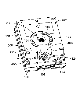
number of different reaction components are provided to the flow channel for
each
cycle. A single sequencing session may include numerous cycles, such as 100,
300,
or more.
[005] The fluids that include the reaction components are typically held in
a
storage device (e.g., tray or cartridge) in which different fluids are stored
in different
reservoirs. Due to the number of reaction components and the large number of
cycles, the total volume of fluid that is used during one session can be quite
large. In
fact, for some applications, it is impractical to supply the total volume of
reaction
components in a single cartridge. For such applications, it may be necessary
to use
a larger system, multiple systems, or to execute numerous sessions with a
single
system. These solutions can be costly, inconvenient, or unreasonable in some
circumstances.
DEFINITIONS
[006] <Blank>
2
Date Recue/Date Received 2020-05-20
WO 2018/071467
PCT/US2017/056032
[007] As used herein, the following terms have the meanings indicated.
[008] Examples described herein include various systems, methods,
assemblies, and apparatuses used to detect desired reactions in a sample for
biological or chemical analysis. In some examples, the desired reactions
provide
optical signals that are detected by an optical assembly. The optical signals
may be
light emissions from labels or may be transmission light that has been
reflected or
refracted by the sample. For example, examples may be used to perform or
facilitate performing a sequencing protocol in which sstDNA is sequenced in a
flow
cell. In particular examples, the examples described herein can also perform
an
amplification protocol to generate a sample-of-interest for sequencing.
[009] Examples herein enable desired reactions to occur where the desired
reactions include a change in at least one of a chemical, electrical,
physical, and
optical property or quality of a substance that is in response to a stimulus.
For
example, the desired reaction may be a chemical transformation, chemical
change,
or chemical interaction. In particular examples, the desired reactions are
detected
by an imaging system. The imaging system may include an optical assembly that
directs optical signals to a sensor (e.g., CCD or CMOS). However, in other
examples, the imaging system may detect the optical signals directly. For
example,
a flow cell may be mounted onto a CMOS sensor. However, the desired reactions
may also be a change in electrical properties. For example, the desired
reaction
may be a change in ion concentration within a solution.
[0010] Exemplary
reactions include, but are not limited to, chemical reactions
such as reduction, oxidation, addition, elimination, rearrangement,
esterification,
amidation, etherification, cyclization, or substitution; binding interactions
in which a
first chemical binds to a second chemical; dissociation reactions in which two
or
more chemicals detach from each other; fluorescence; luminescence;
chemiluminescence; and biological reactions, such as nucleic acid replication,
nucleic acid amplification, nucleic acid hybridization, nucleic acid ligation,
phosphorylation, enzymatic catalysis, receptor binding, or ligand binding.
The
3
Date Recue/Date Received 2020-05-20
CA 03026729 2018-12-05
WO 2018/071467
PCT/US2017/056032
desired reaction can also be addition or elimination of a proton, for example,
detectable as a change in pH of a surrounding solution or environment.
[0011] Various
examples include providing a reaction component to a sample.
As used herein, a "reaction component" or "reactant" includes any substance
that
may be used to obtain a desired reaction. For example, reaction components
include reagents, enzymes, samples, other biomolecules, and buffer solutions.
The
reaction components are typically delivered to a reaction site (e.g., area
where the
sample is located) in a solution or immobilized within a reaction site. The
reaction
components may interact directly or indirectly with the substance of interest.
[0012] In
particular examples, the desired reactions are detected optically
through an optical assembly. The optical assembly may include an optical train
of
optical components that cooperate with one another to direct the optical
signals to an
imaging device (e.g., CCD, CMOS, or photomultiplier tubes). However, in
alternative
examples, the sample region may be positioned immediately adjacent to an
activity
detector that detects the desired reactions without the use of an optical
train. The
activity detector may be able detect predetermined events, properties,
qualities, or
characteristics within a predefined volume or area. For example, an activity
detector
may be able to capture an image of the predefined volume or area. An activity
detector may be able detect an ion concentration within a predefined volume of
a
solution or along a predefined area. Exemplary activity detectors include
charged-
coupled devices (CCD's) (e.g., CCD cameras); photomultiplier tubes (PMT's);
molecular characterization devices or detectors, such as those used with
nanopores;
microcircuit arrangements, such as those described in U.S. Patent No.
7,595,883,
which is incorporated herein by reference in the entirety; and CMOS-fabricated
sensors having field effect transistors (FET's), including chemically
sensitive field
effect transistors (chemFET), ion-sensitive field effect transistors (ISFET),
and/or
metal oxide semiconductor field effect transistors (MOSFET).
[0013] As used
herein, the term "illumination element" and "optical components"
includes various elements that affect the propagation of optical signals.
For
example, the optical components may at least one of redirect, filter, shape,
magnify,
or concentrate the optical signals. The optical signals that may be affected
include
the optical signals that are upstream from the sample and the optical signals
that are
4
CA 03026729 2018-12-05
WO 2018/071467
PCT/US2017/056032
downstream from the sample. In a fluorescence-detection system, upstream
components include those that direct excitation radiation toward the sample
and
downstream components include those that direct emission radiation away from
the
sample. Optical components may be, for example, reflectors, dichroics, beam
splitters, collimators, lenses, filters, wedges, prisms, mirrors, detectors,
and the like.
Optical components also include bandpass filters, optical wedges, and optical
devices similar to those described herein.
[0014] As used
herein, the term "optical signals' or "light signals" includes
electromagnetic energy capable of being detected. The term
includes light
emissions from labeled biological or chemical substances and also includes
transmitted light that is refracted or reflected by optical substrates.
Optical or light
signals, including excitation radiation that is incident upon the sample and
light
emissions that are provided by the sample, may have one or more spectral
patterns.
For example, more than one type of label may be excited in an imaging session.
In
such cases, the different types of labels may be excited by a common
excitation light
source or may be excited by different excitation light sources at different
times or at
the same time. Each type of label may emit optical signals having a spectral
pattern
that is different from the spectral pattern of other labels. For example, the
spectral
patterns may have different emission spectra. The light emissions may be
filtered to
separately detect the optical signals from other emission spectra.
[0015] The
illumination element and/or optical components may have fixed
positions in the optical assembly or may be selectively moveable. As used
herein,
when the term "selectively" is used in conjunction with "moving" and similar
terms,
the phrase means that the position of the optical component may be changed in
a
desired manner. At least one of the locations and the orientation of the
optical
component may be changed. For example, in particular examples, a rotatable
mirror
is selectively moved to facilitate focusing an optical imaging system.
[0016] Analysis
operations (also referred to as imaging sessions) include a time
period in which at least a portion of the sample is imaged. One sample may
undergo
or be subject to multiple imaging sessions. For example, one sample may be
subject to two different imaging sessions in which each imaging session
attempts to
detect optical signals from one or more different labels. As a specific
example, a first
WO 2018/071467
PCT/US2017/056032
scan along at least a portion of a nucleic acid sample may detect labels
associated
with nucleotides A and C and a second scan along at least a portion of the
sample
may detect labels associated with nucleotides G and T. In sequencing examples,
separate sessions can occur in separate cycles of a sequencing protocol. Each
cycle can include one or more imaging session. In other examples, detecting
optical
signals in different imaging sessions may include scanning different samples.
Different samples may be of the same type (e.g., two microarray chips) or of
different
types (e.g., a flow cell and a microarray chip).
[0017] During an
analysis operation, optical signals provided by the sample are
observed. Various types of imaging may be used with examples described herein.
For example, examples described herein may utilize a "step and shoot"
procedure in
which regions of a sample area are individually imaged. Examples may also be
configured to perform at least one of epi-fluorescent imaging and total-
internal-
reflectance-fluorescence (TIRF) imaging. In other examples, the sample imager
is a
scanning time-delay integration (TDI) system. Furthermore, the imaging
sessions
may include "line scanning" one or more samples such that a linear focal
region of
light is scanned across the sample(s). Some methods of line scanning are
described, for example, in U.S. Patent No. 7,329,860 and U.S. Pat. Pub. No.
2009/0272914.
Imaging sessions may also include moving a point focal
region of light in a raster pattern across the sample(s). In alternative
examples,
imaging sessions may include detecting light emissions that are generated,
without
illumination, and based entirely on emission properties of a label within the
sample
(e.g., a radioactive or chemiluminescent component in the sample). In
alternative
examples, flow cells may be mounted onto an imager (e.g.. CCD or CMOS) that
detects the desired reactions.
[0018] As used
herein, the term "sample" or "sample-of-interest" includes various
materials or substances of interest that undergo an imaging session where
optical
signals from the material or substance are observed. In particular examples, a
sample may include biological or chemical substances of interests and,
optionally, an
optical substrate or support structure that supports the biological or
chemical
substances. As such, a sample may or may not include an optical substrate or
support structure. As used herein, the term "biological or chemical
substances" may
6
Date Recue/Date Received 2020-05-20
WO 2018/071467
PCT/US2017/056032
include a variety of biological or chemical substances that are suitable for
being
imaged or examined with the optical systems described herein. For example,
biological or chemical substances include biomolecules, such as nucleosides,
nucleic acids, polynucleotides, oligonucleotides, proteins, enzymes,
polypeptides,
antibodies, antigens, ligands, receptors, polysaccharides, carbohydrates,
polyphosphates, nanopores, organelles, lipid layers, cells, tissues,
organisms, and
biologically active chemical compound(s) such as analogs or mimetics of the
aforementioned species. Other chemical substances include labels that can be
used
for identification, examples of which include fluorescent labels and others
set forth in
further detail below.
[0019] Different
types of samples may include different optical substrates or
support structures that affect incident light in different manners. In
particular
examples, samples to be detected can be attached to one or more surfaces of a
substrate or support structure. For example, flow cells may include one or
more flow
channels. In flow cells, the flow channels may be separated from the
surrounding
environment by top and bottom layers of the flow cell. Thus, optical signals
to be
detected are projected from within the support structure and may transmit
through
multiple layers of material having different refractive indices. For example,
when
detecting optical signals from an inner bottom surface of a flow channel and
when
detecting optical signals from above the flow channel, the optical signals
that are
desired to be detected may propagate through a fluid having an index of
refraction,
through one or more layers of the flow cells having different indices of
refraction, and
through the ambient environment having a different index of refraction.
[0020] The
systems and methods set forth herein can be used to detect the
presence of a particular target molecule in a sample contacted with the
microarray.
This can be determined, for example, based on binding of a labeled target
analyte to
a particular probe of the microarray or due to a target-dependent modification
of a
particular probe to incorporate, remove, or alter a label at the probe
location. Any
one of several assays can be used to identify or characterize targets using a
microarray as described, for example, in U.S. Patent Application Publication
Nos.
2003/0108867; 2003/0108900; 2003/0170684; 2003/0207295; or 2005/0181394.
7
Date Recue/Date Received 2020-05-20
WO 2018/071467
PCT/US2017/056032
[0021]
Furthermore, optical systems described herein may be constructed to
include various components and assemblies as described in PCT application
PCT/US07/07991, entitled "System and Devices for Sequence by Synthesis
Analysis", filed March 30, 2007 and/or to include various components and
assemblies as described in International Publication No. WO 2009/042862,
entitled
"Fluorescence Excitation and Detection System and Method", filed September 26,
2008.
In particular examples, optical systems can include
various components and assemblies as described in U.S. Patent No. 7,329,860
and
WO 2009/137435.
Optical systems can also include various components and
assemblies as described in U.S. Patent Application No. 12/638,770, filed on
December 15, 2009.
[0022] In
particular examples, methods, and optical systems described herein
may be used for sequencing nucleic acids. For example, sequencing-by-synthesis
(SBS) protocols are particularly applicable. In SBS,
pluralities of fluorescently
labeled modified nucleotides are used to sequence a plurality of clusters of
amplified
DNA (possibly millions of clusters) present on the surface of an optical
substrate
(e.g., a surface that at least partially defines a channel in a flow cell).
The flow cells
may contain nucleic acid samples for sequencing where the flow cells are
placed
within the appropriate flow cell holders. The samples for sequencing can take
the
form of single nucleic acid molecules that are separated from each other so as
to be
individually resolvable, amplified populations of nucleic acid molecules in
the form of
clusters or other features, or beads that are attached to one or more
molecules of
nucleic acid. Accordingly, sequencing can be carried out on an array such as
those
set forth previously herein. The nucleic acids can be prepared such that they
comprise an oligonucleotide primer adjacent to an unknown target sequence. To
initiate the first SBS sequencing cycle, one or more differently labeled
nucleotides,
and DNA polymerase, etc., can be flowed into/through the flow cell by a fluid
flow
subsystem (not shown). Either a single type of nucleotide can be added at a
time, or
the nucleotides used in the sequencing procedure can be specially designed to
possess a reversible termination property, thus allowing each cycle of the
8
Date Recue/Date Received 2020-05-20
WO 2018/071467
PCT/US2017/056032
sequencing reaction to occur simultaneously in the presence of several types
of
labeled nucleotides (e.g. A, C, T, G). The nucleotides can include detectable
label
moieties such as fluorophores. Where the four nucleotides are mixed together,
the
polymerase is able to select the correct base to incorporate and each sequence
is
extended by a single base. Non-incorporated nucleotides can be washed away by
flowing a wash solution through the flow cell. One or more lasers may excite
the
nucleic acids and induce fluorescence. The fluorescence emitted from the
nucleic
acids is based upon the fluorophores of the incorporated base, and different
fluorophores may emit different wavelengths of emission light. A deblocking
reagent
can be added to the flow cell to remove reversible terminator groups from the
DNA
strands that were extended and detected. The deblocking reagent can then be
washed away by flowing a wash solution through the flow cell. The flow cell is
then
ready for a further cycle of sequencing starting with introduction of a
labeled
nucleotide as set forth above. The fluidic and detection steps can be repeated
several times to complete a sequencing run. Exemplary sequencing methods are
described, for example, in Bentley et al., Nature 456:53-59 (2008), WO
04/018497;
US 7,057,026; WO 91/06678; WO 07/123744; US 7,329,492; US 7,211,414; US
7,315,019; US 7,405,281, and US 2008/0108082.
[0023] In some
examples, nucleic acids can be attached to a surface and
amplified prior to or during sequencing. For example, amplification can be
carried
out using bridge amplification to form nucleic acid clusters on a surface.
Useful
bridge amplification methods are described, for example, in U.S. Patent No.
5,641,658; U.S. Patent Publ. No. 2002/0055100; U.S. Patent No. 7,115,400; U.S.
Patent Publ. No. 2004/0096853; U.S. Patent Publ. No. 2004/0002090; U.S. Patent
Publ. No. 2007/0128624; and U.S. Patent Publ. No. 2008/0009420. Another useful
method for amplifying nucleic acids on a surface is rolling circle
amplification (RCA),
for example, as described in Lizardi et al., Nat. Genet. 19:225-232 (1998) and
US
2007/0099208 Al. Emulsion
PCR on beads can also be used, for example as described in Dressman et al.,
Proc.
Natl. Acad. Sci. USA 100:8817-8822 (2003), WO 05/010145, or U.S. Patent Publ.
Nos. 2005/0130173 or 2005/0064460.
9
Date Recue/Date Received 2020-05-20
WO 2018/071467
PCT/US2017/056032
[0024] Other
sequencing techniques that are applicable for use of the methods
and systems set forth herein are pyrosequencing, nanopore sequencing, and
sequencing by ligation. Exemplary pyrosequencing techniques and samples that
are
particularly useful are described in US 6,210,891; US 6,258,568; US 6,274,320
and
Ronaghi, Genome Research 11:3-11 (2001).
Exemplary nanopore techniques and samples that are also useful are
described in Deamer et al., Acc. Chem. Res. 35:817-825 (2002); Li et al., Nat.
Mater.
2:611-615 (2003); Soni et al., Olin Chem. 53:1996-2001 (2007) Healy et al.,
Nanomed. 2:459-481 (2007) and Cockroft et al., J. am. Chem. Soc. 130:818-820;
and US 7,001,792. In
particular,
these methods utilize repeated steps of reagent delivery. An instrument or
method
set forth herein can be configured with reservoirs, valves, fluidic lines and
other
fluidic components along with control systems for those components in order to
introduce reagents and detect optical signals according to a desired protocol
such as
those set forth in the references cited above. Any of a variety of samples can
be
used in these systems such as substrates having beads generated by emulsion
PCR, substrates having zero-mode waveguides, substrates having integrated CMOS
detectors, substrates having biological nanopores in lipid bilayers, solid-
state
substrates having synthetic nanopores, and others known in the art. Such
samples
are described in the context of various sequencing techniques in the
references cited
above and further in US 2005/0042648; US 2005/0079510; US 2005/0130173; and
WO 05/010145.
[0025] Exemplary
labels that can be detected in accordance with various
examples, for example, when present on or within a support structure include,
but
are not limited to, a chromophore; luminophore; fluorophore; optically encoded
nanoparticles; particles encoded with a diffraction-grating;
electrochemiluminescent
label such as Ru(bpy)32+; or moiety that can be detected based on an optical
characteristic. Fluorophores that may be useful include, for example,
fluorescent
lanthanide complexes, including those of Europium and Terbium, fluorescein,
rhodamine, tetramethylrhodamine, eosin, erythrosin, coumarin, methyl-
coumarins,
pyrene, Malacite green, Cy3, Cy5, stilbene, Lucifer Yellow, Cascade BlueTM,
Texas
Red, alexa dyes, phycoerythin, bodipy, and others known in the art such as
those
described in Haugland, Molecular Probes Handbook, (Eugene, OR) 6th Edition;
The
Date Recue/Date Received 2020-05-20
WO 2018/071467
PCT/US2017/056032
Synthegen catalog (Houston, TX.), Lakowicz, Principles of Fluorescence
Spectroscopy, 2nd Ed., Plenum Press New York (1999), or WO 98/59066.
In some examples, the one pair of labels
may be excitable by a first excitation wavelength and another pair of labels
may be
excitable by a second excitation wavelength.
[0026] Although
examples are exemplified with regard to detection of samples
that include biological or chemical substances supported by an optical
substrate, it
will be understood that other samples can be imaged by the examples described
herein. Other
exemplary samples include, but are not limited to, biological
specimens such as cells or tissues, electronic chips such as those used in
computer
processors, and the like. Examples of some of the applications include
microscopy,
satellite scanners, high-resolution reprographics, fluorescent image
acquisition,
analyzing and sequencing of nucleic acids, DNA sequencing, sequencing-by-
synthesis, imaging of microarrays, imaging of holographically encoded micro-
particles and the like.
SUMMARY
[0027] In
accordance with examples herein, a cartridge assembly for use with a
fluidics analysis instrument is provided. The cartridge assembly comprises
housing,
including a flow cell chamber to receive a flow cell, and a well plate having
liquid
wells to receive desired amounts of liquids. The well plate includes a valve
station, a
pump station and a fluidics analysis station. The well plate includes channels
associated with the wells, the valve station, pump station and fluidics
analysis
station. A pump assembly is provided on the well plate at the pump station.
The
pump assembly manages fluid flow through the channels between the pump station
and the fluidics analysis station. A rotary valve assembly is positioned on
the well
plate at the valve station. The rotary valve assembly includes a rotor shaft
and rotor
valve positioned to rotate about a rotational axis and to selectively couple
the wells
to the pump station. The rotor shaft has a distal end exposed through the
housing.
The rotor shaft includes a dual spline configuration at the distal end
thereof. The dual
spline configuration has first and second sets of splines. The first set of
splines forms
a drive interface and the second set of splines forms a position encoding
interface.
The position encoding interface is utilized by the valve drive assembly to
track a
11
Date Recue/Date Received 2020-05-20
CA 03026729 2018-12-05
WO 2018/071467
PCT/US2017/056032
position of the rotor shaft.
[0028] Optionally, the first set of splines represent exterior splines
extending about
an exterior of the distal end, wherein lateral sides of adjacent splines are
separated
by a first predetermined spline to spline spacing. The spline to spline
spacing
corresponds to a spline pattern on a drive shaft of a valve drive assembly.
The
second set of splines may represent interior splines formed about an interior
of a
cavity provided at the distal end of the rotor shaft. The interior splines may
have
lateral sides that are angled such that adjacent lateral sides form a
predetermined
non-parallel angle with respect to one another. The adjacent lateral sides may
merge
at a bottom to form pockets to receive mating splines on a drive shaft of the
valve
drive assembly.
[0029] Optionally,
the rotor valve may be mounted to a proximal end of the rotor
shaft through a coupling flange. The coupling flange may allow a predetermined
amount of tilting movement between the rotor valve and rotor shaft. The rotor
valve
may include a rotor base having one or more ribs positioned about a proximal
end of
the rotor shaft. The coupling flange may be held between the ribs and the
proximal
end of the rotor shaft. The rotor valve may include well plate engaging face
having a
central port and a radial port. The rotor valve may include a channel oriented
to
extend in a radial direction outward from the central port to the radial port.
[0030] Optionally,
the central port may be aligned to correspond with a rotational
axis of the rotor shaft and align with a central feed port in the well plate.
The rotor
valve may rotate about the rotational axis to align the radial port with a
corresponding well port. The rotary valve may include a well plate engaging
face
formed with an interface ring thereon. The interface ring may extend about a
perimeter of the well plate engaging face. The cartridge assembly may further
comprise a valve cap including an interior cavity to rotatably receive the
rotary valve.
The valve cap may include one or more latch arms to secure the valve cap to
the
wells and downward against the well plate. A biasing element may be within the
interior cavity and may apply a biasing force against the rotary valve to
maintain a
sealed interface between ports in the rotary valve and ports in the well
plate.
[0031] Optionally,
the pump assembly may include a plunger having a drive end
and a biasing surface located at opposite ends of the plunger. The drive end
and
12
CA 03026729 2018-12-05
WO 2018/071467
PCT/US2017/056032
biasing surface may be exposed at upper and lower surfaces of the housing such
that corresponding unidirectional drive and biasing forces are applied thereto
in
connection with moving the plunger in a reciprocating motion. The plunger may
have a drive arm and a plunger arm joined with one another through a bridge
segment in a U-shape and may be formed together in a monolithic structure. The
drive and plunger arms may be received within support posts located on the
well
plate. The plunger may comprise a plunger arm and plunger element that are
molded together from different materials. The plunger element may be formed on
a
leading end of the plunger arm. The plunger element may move within the
corresponding support post to form high and low pressure states at the pumping
station.
[0032] Optionally,
the pump station may include a channel segment functionally
divided into a preparation segment, a discharge segment and a pump work
segment,
all of which are formed continuous with one another to support fluid flow in
either
direction. The pump station may include a work area sandwiched between a pair
of
pinch valves located upstream and downstream of the work area. The pump
assembly may comprise a plunger aligned with the work area. The plunger may
reciprocally move toward and away from the work area to introduce high and low
pressure states. The pump assembly may further comprise push pins aligned with
the pinch valves. The push pins may be alternately moved to open and close the
pinch valves. A piercer unit may be provided in the housing and positioned
proximate
to the wells. The piercer unit may include a piercer element. The piercer unit
may be
moved to a piercing position where the piercer element pierces a cover for the
corresponding well.
[0033] Optionally, the housing may include a cover having a piercer access
opening that provides an instrument access to an upper end of the piercer
unit. The
piercer unit may include a body that is shaped in a conical tubular manner
with a
lower platform, an intermediate segment and an upper flange, at least one of
the
lower platforms or upper flange including piercing elements distributed in a
predetermined manner. The piercing elements may be arranged to align with the
wells on the well plate. A piercer unit may have a platform that fits over the
rotor
shaft. The platform may include indexing features that engage mating features
on
the rotary valve assembly to locate the piercer unit in a predetermined
rotational
13
CA 03026729 2018-12-05
WO 2018/071467
PCT/US2017/056032
orientation with respect to the rotor shaft in order to align piercer elements
with
corresponding wells.
[0034] Optionally,
the well plate may include well transition ports arranged in a
predetermined pattern corresponding to the rotary valve assembly. The well
plate
may include well discharge ports aligned with corresponding wells. The well
plate
may include well discharge channels extending between corresponding well
discharge ports and well transition ports. The well plate may include a base
having
top and bottom surfaces, at least one of which includes the channels. The
channels
may include open sided channels. The base may be joined to a backing layer to
close the open sided channels. The well plate may include an optical interface
window, provided within the optical analysis station. A top side of the well
plate may
include an insertion limit element to engage an illumination element on an
instrument. The insertion limit element may represent one or more ribs that
are
provided about the optical interface window. The ribs may define a Z-tolerance
between an illumination element and the optical interface window.
[0035] In
accordance with examples herein, a fluidics system is provided
comprising a cartridge assembly that has a housing that includes an
illumination
chamber and a well plate. The well plate is maintained within the housing and
has
liquid wells to receive desired amounts of liquids. The well plate includes a
fluidics
analysis station aligned with the illumination chamber. The well plate
includes an
interface window and interface ports located at the fluidics analysis station.
A flow
cell cartridge has a frame that contains an analysis circuit therein. The
frame
includes a flow cell window aligned with the analysis circuit. The frame
includes flow
cell ports that are fluidly coupled to an active area in the analysis circuit.
The housing
includes a flow cell chamber to receive the flow cell cartridge. The flow cell
chamber
to position the flow cell cartridge at the fluidics analysis station with the
flow cell
window and ports aligned with the corresponding interface window and ports,
respectively.
[0036] Optionally,
the flow cell chamber may include side rails and end stop, at
least one of which has an end limit to position the flow cell cartridge, when
in a fully
loaded position, at a predetermined datum point such that the flow cell window
and
ports aligned with the corresponding interface window and ports, respectively.
The
14
CA 03026729 2018-12-05
WO 2018/071467
PCT/US2017/056032
flow cell chamber may include a biasing arm that may be oriented to extend
along at
least one of the side rails. The biasing arm may extend inward toward the flow
cell
chamber and to apply a lateral biasing force upon the flow cell cartridge to
maintain
the flow cell cartridge at the predetermined datum point. The biasing arm may
include a latch element positioned to fit with a notch provided in a lateral
side of the
flow cell cartridge. The latch element may maintain the flow cell cartridge at
an X
datum point relative to an XYZ coordinate system (as described herein).
[0037] Optionally,
the flow cell cartridge may include top and bottom frames. The
top frame may include the flow cell window and ports. The top frame may
include a
rib extending upward from the top frame by a predetermined height to define a
Z
datum point relative to an XYZ coordinate system. The flow cell cartridge may
include gaskets formed in a monolithic manner from an elastomer material. The
well
plate may include a valve station, pump station and interface channels. The
interface
channels may provide a first fluidic path between the valve station and one of
the
interface ports and a second fluidic path between the pump station and one of
the
interface ports. The illumination chamber may be oriented to extend along an
illumination axis that may extend through the interface window, flow cell
window and
the active area within the analysis circuit.
BRIEF DESCRIPTIONS OF THE DRAWINGS
[0038] Figures 1A
illustrates a front top perspective view of a cartridge assembly
formed in accordance with an example herein.
[0039] Figure 1B
illustrates a bottom perspective view of the cartridge assembly
of Figure 1A in accordance with an example herein.
[0040] Figure 1C
illustrates a front perspective view of internal components
within the cartridge assembly in accordance with an example herein.
[0041] Figure 1D
illustrates a top perspective view of a waste tray that is
mounted below the well plate and forms part of the housing of the cartridge
assembly in accordance with examples herein.
[0042] Figure 1 E
illustrates a front perspective view of a portion of the cartridge
assembly and a flow cell cartridge align with the flow cell chamber in
accordance
CA 03026729 2018-12-05
WO 2018/071467
PCT/US2017/056032
with examples herein.
[0043] Figure 1F
illustrates a bottom plan view of the flow cell chamber with a
flow cell cartridge inserted therein in accordance with an example herein.
[0044] Figure 2A
illustrates a perspective view of a rotary valve assembly formed
in accordance with an example herein.
[0045] Figure 2B
illustrates an enlarged perspective view of the distal end of the
rotor shaft in accordance with examples herein.
[0046] Figure 20
illustrates a side sectional view of the rotary valve assembly
which includes the valve shaft in accordance with examples herein.
[0047] Figure 2D
illustrates a top perspective view of the rotor valve formed in
accordance with an example herein.
[0048] Figure 2E
illustrates a bottom plan view of the rotor valve formed in
accordance with an example herein.
[0049] Figure 2F
illustrates a side perspective view of the rotor shaft and rotor
valve with the rotor cap removed in accordance with an example herein.
[0050] Figure 3A
illustrates a bottom perspective view of the piercer unit formed
in accordance with an example herein
[0051] Figure 3B
illustrates a top view of a portion of the piercing unit when
installed on the rotary valve assembly in accordance with an example herein.
[0052] Figure 3C
illustrates the rotary valve assembly with the piercing unit
removed to better illustrate the valve shaft in accordance with an example
herein.
[0053] Figure 4A illustrates a bottom view of a portion of the cartridge
assembly to
illustrate the illumination chamber in more detail in accordance with examples
herein.
[0054] Figure 4B illustrates a model side sectional view through the various
structures provided at the fluidics analysis station once a flow cell
cartridge is
inserted and an illumination element is inserted into the illumination chamber
in
accordance with an example herein.
16
CA 03026729 2018-12-05
WO 2018/071467
PCT/US2017/056032
[0055] Figure 5A illustrates a front perspective view of the well plate formed
in
accordance with an example herein.
[0056] Figure 5B illustrates flow channels provided on the back surface of the
base
of the well plate in accordance with an example herein.
[0057] Figure 5C illustrates a bottom plan view of a portion of the base to
provide a
more detailed view of the fluidics analysis station on the back surface of the
well
plate in accordance with examples herein.
[0058] Figure 5D illustrates a top plan view of a front/top portion of the
base
corresponding to Figure 5C to provide a more detailed view of the fluidics
analysis
station on a front surface of the well plate in accordance with examples
herein.
[0059] Figure 5E illustrates an enlarged portion of the bottom surface of the
base
proximate to the valve station in accordance with examples herein.
[0060] Figure 6A illustrates a top plan view of the pump station on the well
plate in
accordance with an example herein.
[0061] Figure 68 illustrates a side view of a plunger provided within the pump
in
accordance with an example herein.
[0062] Figure 6C illustrates an enlarged side view of the plunger element as
mounted
to the plunger arm in accordance with an example herein.
[0063] Figure 6D illustrates a side sectional view of the pump station to
better
illustrate the pumping operation in accordance with an example herein.
[0064] Figure 6E illustrates an enlarged side perspective view of a portion of
the
plunger inserted into the support post in accordance with an example herein.
[0065] Figure 6F illustrates a perspective view of the support shaft to
receive the
plunger arm in accordance with examples herein.
[0066] Figure 7 illustrates a block diagram of a portion of a fluidics
instrument utilized
in accordance with an example herein.
[0067] Figure 8 is a schematic view of a system configured for biological or
chemical
17
CA 03026729 2018-12-05
WO 2018/071467
PCT/US2017/056032
analysis formed in accordance with one example.
[0068] Figure 9A illustrates a top perspective view of a flow cell cartridge
formed in
accordance with an example herein.
[0069] Figure 9B illustrates an enlarged view of a portion of the top frame to
better
illustrate an optical fluidic (0-F) interface to the flow cell cartridge in
accordance with
examples herein.
[0070] Figure 9C illustrates a bottom perspective view of the flow cell
cartridge of
Figure 9A in accordance with examples herein.
[0071] Figure 9D illustrates a top view of a portion of a printed circuit
board provided
within the flow cell cartridge formed in accordance with an example herein.
[0072] Figure 9E illustrates a bottom view of the printed circuit board of
Figure 9D
formed in accordance with an example herein.
DETAILED DESCRIPTION
Cartridge Assembly Overview
[0073] Figure 1A
illustrates a front top perspective view of a cartridge assembly
100 formed in accordance with an example herein. By way of example the
cartridge
assembly 100 may represent an SBS cartridge assembly. The cartridge assembly
100 includes a housing to be inserted into a micro-fluidics instrument. While
examples herein are described in connection with micro-fluidics systems,
instruments and cartridges, optionally examples may be implemented with
fluidics
systems that may not otherwise be considered "micro' fluidics system,
instruments,
cartridges, etc. The housing includes a base 101 and a cover 102. The cover
102
includes an instrument engaging surface 104 that includes openings to expose
internal components that are engaged by multiple instrument components
described
below in more detail. During operation, the cartridge assembly 100 is
positioned
proximate to an instrument that physically, optically and electrically couples
to the
cartridge assembly 100 in connection with performing a fluidics operation. The
cartridge assembly 100 includes a front face 106 that includes a flow cell
chamber
108 to receive a flow cell in connection with performing a fluidics operation.
18
CA 03026729 2018-12-05
WO 2018/071467
PCT/US2017/056032
[0074] In
accordance with examples herein, the cartridge assembly 100 includes
various subassemblies including a rotary valve assembly 200 (described below
in
more detail in connection with Figures 2A-2D), a piercer unit 300 (described
below in
more detail in connection with Figures 3A-3D), an illumination chamber 400
(described below in more detail in connection with Figure 4), and a syringe
pump
assembly 500 (described below in more detail in connection with Figures 6A-
60).
[0075] The cover
102 includes a shaft well 116 that exposes a valve shaft within
the rotary valve assembly 200. The cover 102 also includes piercer access
openings
122 that provide the instrument access to an upper end of the piercer unit 300
in
connection with operations described herein. During operation, a drive shaft
on the
instrument is physically coupled to the valve shaft of the rotary valve
assembly 200
to manage movement of the rotary valve assembly 200. The cover 102 includes
piercer access openings 122 that provide one or more piercer shafts on the
instrument access to an upper end of the piercer unit 300 in connection with a
well
foil piercing operation. By way of example, multiple piercer access openings
122
may be provided in a distributed manner across an upper end of the piercer
unit 300
in order to maintain planar motion of the piercer unit 300 when being
activated. A
sample well 124 is provided proximate to the front face 106. The sample well
124 is
to receive a sample quantity of interest to be analyzed by the instrument. A
heating
element 125 may be provided proximate to the sample well 124 to adjust the
temperature of incoming samples as desired (e.g., to preheat). A pump access
opening 123 is provided in the upper surface 104 of the cover 102. The pump
access
opening 123 is to allow a biasing element within the instrument to engage a
spring
engaging surface 542 on a plunger of the pump assembly 500. For example, the
biasing element may be a metal wave spring, an elastomeric spring, or another
structure that provides a uniform force.
[0076] Figure 1B
illustrates a bottom perspective view of the cartridge assembly
100 of Figure 1A. In Figure 1B, a flow cell cartridge 900 is provided within
the flow
cell chamber 108. The cartridge assembly 100 includes a bottom surface 110
having
a flow cell cartridge access area 112 that exposes portions of interest on the
flow cell
cartridge 900, such as an array of electrical contact pads 950 and an opening
944 to
receive a heater element. The bottom surface 110 also includes a pair of
pushpin
openings 114 and a pump drive opening 116. The pushpin openings 114 expose
19
CA 03026729 2018-12-05
WO 2018/071467
PCT/US2017/056032
pushpins within the pump 500. As explained herein, the pushpins are engaged by
valve drive shafts within the instrument to open and close corresponding pinch
valves in connection with managing fluid flow. The pump drive opening 116
exposes
a proximal end 548 of a valve shaft 546 within the pump 500. As explained
herein,
the valve shaft 546 is engaged by a pump drive shaft within the instrument to
introduce a pumping action in connection with managing fluid flow. The bottom
surface 110 also includes an opening 118 to expose a pierceable waste
discharge
port 120 that is utilized to drain used fluids from a waste container within
the
cartridge assembly 100.
[0077] Figure 1C
illustrates a front perspective view of internal components
within the cartridge assembly 100 in accordance with an example herein. As
shown
in Figure 10, the cartridge assembly 100 includes a rotary valve 200 assembly
rotatably mounted onto a well plate 150 in a valve operating station. A
syringe pump
assembly 500 is mounted onto the well plate 150 in a pumping station. The well
plate
150 includes a base 152 (e.g., a generally planar later) with multiple reagent
wells
154, 156 formed with and extending upward from the base 152. The reagent wells
154, 156 are provided at various positions at least partially surrounding the
rotary
valve assembly 200. The reagent wells are to receive desired amounts of
liquids.
Optionally, the wells 154, 156 may include samples and other liquids. As
explained
herein, the rotary valve assembly 200 selectively couples the reagent wells 1
54, 156
(generally referred to as liquid wells) to the fluidics analysis station 170.
[0078] The reagent
wells 154, 156 may be formed with different cross-sectional
areas and have different heights extending above the base 152 to define
different
well volumes to receive a desired quantity of liquid for the corresponding
reagent.
Optionally, one or more of the wells 154, 156 may be utilized as solution
wells in
accordance with examples herein. The wells 154, 156 include filling ends 158,
160
that are open to receive a desired amount of liquid during a filling
operation. Once
the desired amount of liquid is added to the wells 1 54, 156, the filling ends
1 58, 160
are covered with a foil or other sealing cover to form an airtight volume
within each of
the wells 154, 156. While not visible in Figure 1C, the wells 154, 156 include
one or
more discharge ports provided in the bottom thereof. During operation, the
cover is
pierced to allow air to enter one or more of the well volumes, thereby
permitting the
liquid to freely flow (e.g. through gravity or under pressure) through the
discharge
CA 03026729 2018-12-05
WO 2018/071467
PCT/US2017/056032
ports to the fluidics analysis station 170 under control of the rotary valve
200 and
pump assembly 500.
[0079] Figure 1D
illustrates a top perspective view of a waste tray 130 that is
mounted below the well plate 150 and forms part of the housing of the
cartridge
assembly 100. The waste tray includes a waste collection volume 131 that spans
an
area below a relatively large portion of the well plate 150. By way of
example, the
waste tray 130 is located below the rotary valve assembly 200 and at least a
portion
of the wells 154, 156. The waste tray 130 includes a ridge 1 32 that extends
about a
perimeter thereof and is sealed to a mating surface (e.g. on the bottom
surface of the
well plate 150). The ridge 132 may include vents 133 in the corners thereof
that
communicate with openings through the well plate 150. The vents 133 permit air
to
discharge from the volume 131 as waste liquids enter the volume 131. The vents
133 are positioned above the area in which the liquid is retained to prevent
leakage.
The vents 133 are distributed to allow the cartridge assembly 100 to be
slightly tilted
during operation such that at least one of the vents 133 will always be usable
as an
air inlet. The vents 133 allow the size of the waste tray 130 to be limited as
waste
liquids are permitted to slosh up to the surface of the vents 133 without
leaking. The
vents 133 may be formed of a porous material, such as expanded poly propylene,
polyethylene or polytetrafluoroethylene.
[0080] The waste
tray 130 also includes a funnel region 134 and a discharge
tube 135. The funnel region 134 terminates at a ledge area 136 that
communicates
with an opening to the tube 135. The bottom end of the tube 135 is initially
closed
with a cover. To empty the waste tray 130, the cover 136 may be pierced and
the
cartridge assembly 100 (including the waste tray 130) tilted with the funnel
region
134 at the lowest point therein. The waste liquids flow through the funnel
region 134
over the ledge area 136 and out of the tube 135.
Flow Cell Chamber
[0081] Figure 1E
illustrates a front perspective view of a portion of the cartridge
assembly 100 and a flow cell cartridge 900 align with the flow cell chamber
108. The
flow cell chamber 108 includes a key feature 109 which may be shaped as a
channel
and provided in the bottom surface of the flow cell chamber 108. The key
feature 109
is shaped and dimensioned to receive a corresponding keying feature (e.g.
standoff
21
CA 03026729 2018-12-05
WO 2018/071467
PCT/US2017/056032
914 Figure 90) on a bottom of the flow cell cartridge 900 to ensure that the
flow cell
cartridge 900 is loaded in the correct direction and orientation. The flow
cell chamber
108 includes side rails 413 and upper and lower walls 451 and 453. The
cartridge
900 is inserted in a loading direction 9A.
[0082] Figure 1F
illustrates a bottom plan view of the flow cell chamber 108 with
a flow cell cartridge 900 inserted therein in accordance with an example
herein. The
flow cell cartridge 900 is inserted into the flow cell chamber 108 to a fully
loaded
position in Figure 1F. As described herein, in more detail in connection with
Figures
9A-9E, the flow cell cartridge 900 includes a loading end 908 and lateral
edges 912.
The loading end 908 includes a reference post 923, while at least one of the
lateral
edges 912 includes one or more lateral reference posts 925. An opposite
lateral
edge 912 includes a notch 927. A bottom side of the flow cell cartridge 900
includes
openings to expose a heat spreader 957 and contact pads 950.
[0083] The flow
cell chamber 108 includes top and bottom surfaces, and lateral
side rails 413 that extend parallel to one another along opposite lateral
sides of the
chamber 108. An end stop 417 is provided at an innermost depth of the chamber
108. The top and bottom surfaces, lateral side rails 413, and end stop 417 are
positioned to orient the flow cell cartridge 900 at predetermined datum points
(e.g.,
reference points referred to as an X datum point, Y datum point and Z datum
point)
relative to a coordinate system (e.g., XYZ coordinate system).The end stop 417
includes an end limiter 414 provided at a desired position along the end stop
417.
The end limiter 414 aligns with a reference post 923 provided on the loading
end
908. One of the side rails 413 includes lateral limits 420 that extend inward
towards
the flow cell chamber 108. The lateral limits 420 align with the lateral
reference post
923. The opposite side rail 413 includes a biasing arm 422 that is oriented to
extend
along the side rail 413 and to apply a lateral biasing force in the direction
of arrow
1E. The biasing arm 422 includes a latch element 424 on a distal end thereof.
The
latch element 424 is shaped to fit in the notch 927 in the side edge 912.
[0084] During a
loading operation, the loading end 908 is inserted into the flow
cell chamber 108 until the reference post 923 firmly abuts against a limit
feature in
the flow cell chamber 108 to define a limit of movement in the loading
direction 9A.
As flow cell cartridge 900 is inserted, the biasing arm 422 rides along the
side edge
22
CA 03026729 2018-12-05
WO 2018/071467
PCT/US2017/056032
912 that includes the notch 927 until the latch element 424 fits within the
notch 927.
The biasing arm 422 applies a lateral force in the direction of arrow 1E (also
represents a lateral positioning force) to shift the flow cell cartridge 900
in the lateral
direction (corresponding to the Y-axis) until the lateral reference posts 923
engage
the lateral limits 420. The lateral limits of the flow cell chamber 108 define
a limit of
movement in the lateral Y-direction. The biasing arm maintains the flow cell
cartridge
900 at the desired Y-position (corresponding to a Y datum point). The latch
element
424 within the notch 927 at a predefined position to maintain the flow cell
cartridge
900 at the desired X-position (corresponding to an X datum point).
[0085] The flow
cell chamber 108 enables a snap-in arrangement for the flow cell
cartridge 900. By enabling the flow cell cartridge 900 to be inserted into and
removed
from the cartridge assembly 100, examples herein allow the flow cell cartridge
to be
managed and shipped separately from the reagents and samples. In addition, by
separating the flow cell cartridge 900 from the reagents, examples herein
allow
separate manufacturing workflows. In addition, examples herein allow flow cell
cartridges to be mixed and matched with various combinations of reagents,
reagent
volumes and flow cell cartridge sizes. For example, one protocol may utilize
larger
volumes of certain reagents, while another protocol utilizes a greater number
of
different reagents, but in smaller volumes. The various criteria for the
number and
volume of reagents may be satisfied by different cartridge assemblies, while
any of
the foregoing cartridge assemblies are able to utilize the same flow cell
cartridge. As
a further example, the same type of cartridge assembly may be utilized with
different
protocols that have different requirements within the analysis circuit. For
example,
one protocol may utilize an analysis circuit that has a large optical
footprint, while
another protocol may utilize an analysis circuit that has a smaller optical
footprint. In
addition, some protocols may utilize analysis circuits that have more complex
electronics and interconnections, as compared to other analysis circuits,
while any of
the foregoing analysis circuits may be embodied within a flow cell cartridge
having a
common overall envelope that fits into the same cartridge assembly.
[0086] Examples
described herein provide an interface having a small height
(e.g. a minimized height) between the analysis circuit and the light source
within the
illumination element of the instrument.
23
CA 03026729 2018-12-05
WO 2018/071467
PCT/US2017/056032
Piercer Unit
[0087] A piercer
unit 300 is provided in the housing and positioned proximate to
the wells 154, 156. The piercer unit 300 is moved to a piercing position where
piercer elements pierce a foil or cover for the corresponding well(s) 154,
156. In the
example of Figure 3A, the piercer unit 300 is mounted on the rotary valve
assembly
200 and is managed during operation by the instrument to pierce one or more of
the
wells 154, 156.
[0088] Figure 3A
illustrates a bottom perspective view of the piercer unit 300 is
formed in accordance with an example herein. The piercer unit 300 is
illustrated with
a partial cut out to better present the overall structure therein. The piercer
unit 300
includes a body 306 that is shaped in a conical tubular manner with a lower
platform
302, an intermediate segment 308 and an upper flange 310. The platform 302,
segment 308, and flange 310 are formed in a monolithic manner. The lower
platform
302 includes a plurality of piercing elements 312 distributed in a
predetermined
manner about the platform 302. In the example of Figure 3A, the piercing
elements
312 are arranged in a circular pattern. The upper flange 310 also includes
piercing
elements 314 provided on a lower surface thereof and projecting in a common
direction as the piercing elements 312. The piercing elements 314 are
distributed
about the upper flange 310 in a predetermined manner, such as in a circular
pattern.
[0089] During
operation, the piercing unit 300 is activated by a piercer actuator
assembly on the instrument. For example, with reference to Figure 1A, the
instrument may extend one or more piercer shafts through the piercer access
ports
122 in the cover 102. The piercer shafts push downward in a piercing direction
318
to force the piercing unit 300 downward, thereby driving the piercing elements
312,
314 through the foil/cover on the corresponding wells 154, 156. The piercer
shafts
are distributed to evenly apply the piercing force to the piercer unit 300.
[0090] In
accordance with at least one example, the piercing elements 312, 314
are formed with an X-shaped cross-section to facilitate piercing the
foil/cover and to
provide venting through the foil/cover. The X-shaped cross-section allows air
to enter
the corresponding well volume even while the piercing elements 312, 314 extend
through the foil/covers.
24
CA 03026729 2018-12-05
WO 2018/071467
PCT/US2017/056032
[0091] In the
example of Figure 3A, a majority the piercing elements 312, 314
have a generally common length. However, optionally various ones of the
piercing
elements 312, 314 may be longer or shorter, such as shown by piercing element
314A. With joint reference to Figures 10 and 3A, the piercing elements 312,
314 are
positioned to align with corresponding wells 154, 156. In the example of
Figures 10
and 3A, the piercing elements 312, 314 generally have a common length to
pierce
each of the corresponding wells 154, 156 at the same time when the piercing
element 300 is activated. Optionally, the piercing unit 300 may be operated
(by the
piercer actuator assembly) as a multistage piercing system such that only a
portion
of the piercing elements 312, 314 pierce corresponding wells 154, 156 during a
first
piercing operation, while a different portion of the piercing elements 312,
314 pierce
corresponding wells 154, 156 during a second piercing operation. For example,
the
piercing elements 312 may be formed longer than the piercing elements 314 such
that the piercing elements 312 pierce corresponding foils during the first
piercing
operation, and the piercing elements 314 pierce corresponding foils during the
second piercing operation.
[0092] The lower
platform 302 includes an internal rim 326 that is formed about
the opening 304. The rim 326 includes multiple indexing features 322 provided
about
the opening 304. The indexing features 322 engage mating features on the
rotary
valve assembly 200 in order to locate the piercer unit 300 in a predetermined
rotational orientation with respect to the rotor shaft 202 in order to align
the piercer
elements 312, 314 with corresponding wells 154, 156. The indexing features 322
include one or more notches 324 which are provided about the internal rim 326.
The
rim 326 projects slightly upward into an interior portion of the body 306
toward the
upper flange 310. The notches 324 are distributed in a predetermined pattern
about
the opening 304. The notches 324 align with ribs or teeth that are provided on
the
rotary valve assembly 200 (as described below in more detail). In the example
of
Figure 3A, notches 324 are relatively evenly positioned about the perimeter of
the
opening 304. Additionally or alternatively, more or fewer notches 324 may be
utilized
and may be positioned in alternative locations in an even or uneven
distribution.
Optionally, an indexing feature other than notches 324 may be utilized.
[0093] The rim 326
also includes one or more flexible standoff 328 that extend
downward into the opening 304 in a direction common with the piercing elements
CA 03026729 2018-12-05
WO 2018/071467
PCT/US2017/056032
312. The standoffs 328 engage a ledge 216A extending about a perimeter of the
base extension 216. Once the notches 324 align with corresponding teeth on the
rotary valve assembly 200, the piercer unit 300 is loaded until the standoffs
328 rest
on a top surface of the ledge 216A. The standoffs 328 remain on the ledge 216A
to
maintain the piercing unit 300 positioned vertically in a non-piercing/ready
position.
During operation, the piercer unit 300 is forced downward (in the direction of
arrow
318) by a piercer shaft, in response to which the standoffs 328 flex outward
and ride
down over the ledge 216A to permit the piercer unit 300 to slide downward in
the
piercing direction 318 further onto the rotor cap 210.
[0094] Figure 3B
illustrates a top view of a portion of the piercing unit 300 when
installed on the rotary valve assembly 200. As explained herein, the rotary
valve
assembly 200 includes a rotor shaft 202 with a valve cap 210 mounted over the
rotor
shaft 202. The valve cap 210 includes a plurality of teeth 212 distributed
peripherally
about a central rim of the valve cap 210. The teeth 212 align with, and are
received
in, the notches 324 on the piercer unit 300 in order to rotationally position
the
piercing unit 300 in a predetermined rotational angle relative to the rotary
valve
assembly 200. While not shown, the latches 328 (Figure 3A) are securely joined
with
latching features on the valve cap 210 to maintain the piercing unit 300 in a
mounted
position along a rotational axis extending along a central axis of the rotor
shaft 202 of
the rotary valve assembly 200.
[0095] Figure 3C
illustrates the rotary valve assembly 200 with the piercing unit
300 removed to better illustrate the rotor shaft 202. The rotor shaft 202 is
elongated
and rotates about a rotational axis 220. The rotor shaft 202 includes a
proximal end
(not visible in Figure 30) and a distal end 204. The valve cap 210 is loaded
over the
distal end 204 of the rotor shaft 202 to an installed position as shown in
Figure 30.
The valve cap 210 includes a cap base 214 that has an enlarged diameter that
is
dimensioned to fit within a collection of wells 156 that are arranged adjacent
one
another in a generally circular manner. The cap base 214 is joined with a cap
extension 216 that extends upward from the cap base 214 along a length of the
rotor
shaft 202. The cap extension 216 has a smaller diameter than the diameter of
the
cap base 214 in the example of Figure 30. However, it is recognized that
alternative
dimensions may be utilized for the cap extension 216 and cap base 214. The cap
extension 216 includes teeth 212 formed upon a periphery of the cap extension
216
26
CA 03026729 2018-12-05
WO 2018/071467
PCT/US2017/056032
and projects outward radially (relative to the rotational axis 220) therefrom.
[0096] The cap base
214 includes one or more latch arms 226 that extend
radially outward from the cap base 214. The latch arms 226 are formed in an L-
shape and dimensioned such that a leg of the latch arm 226 fits between
adjacent
wells 156, while an outer portion or foot on the latch arm 226 bends about and
rests
securely against an outer surface of one of the wells 156. The corresponding
well
156 includes a detent 158 provided on an outer wall of the well 156. The L-
shaped
latch arm 226 snaps over and is held securely below the detent 158 when the
valve
cap 210 is inserted over the rotor shaft 202.
Rotary Valve Assembly
[0097] Next, the
operation of the rotary valve assembly 200 will be described in
connection with Figures 2A-2F.
[0098] Figure 2A
illustrates a perspective view of a rotary valve assembly 200
formed in accordance with an example herein. Figure 2A better illustrates the
valve
cap 210 provided over the rotor shaft 202. The rotor shaft 202 rotates within
the
valve cap 210, with the valve cap 210 maintaining the rotor shaft 202 at a
predetermined position with respect to the well plate 150. The valve cap 210
includes multiple latch arms 226 distributed evenly about a perimeter of the
cap base
214. A distal end 204 of the rotor shaft 202 projects beyond the cap extension
216.
The distal end 204 includes a plurality of exterior splines 230 distributed
about the
rotor shaft 202. The distal end 204 also includes a cavity 228 that includes
interior
splines 232 distributed about the cavity 228. The rotor shaft 202 includes a
dual
spline configuration having the interior and exterior splines 232, 230 (also
referred to
as first and second sets of splines) that mate with a matching spline
configuration on
a drive shaft of a valve drive assembly within the instrument that engages the
cartridge assembly during a fluidics operation. The dual spline configuration
of
interior and exterior splines 232, 230 provides a drive interface and a
position
encoding interface to precisely track a rotational relation between the drive
shaft of
the instrument and the rotor shaft 202.
[0099] The valve
cap 210 is illustrated in a partially transparent manner to show
a rotor valve 234 below the valve cap 210 and mounted about a proximal end of
the
27
CA 03026729 2018-12-05
WO 2018/071467
PCT/US2017/056032
rotor shaft 202. The rotor valve 234 is secured to the rotor shaft 202 and
rotates with
the rotor shaft 202. The rotor valve 234 rotates within (and relative to) the
cap base
214, while the cap base 214 remains stationary with the latch arms 226 secured
about corresponding wells on the well plate 150. An inner diameter of the cap
extension 216 corresponds to an outer diameter of the rotor shaft 202 to
provide a
close tolerance there between. The cap extension 216 has a length 217 that may
be
varied, provided that the cap extension 216 affords sufficient structural and
rotational
support to the rotor shaft 202, whereby the rotational axis of the rotor shaft
202 is
maintained at a predetermined fixed point relative to the well plate 150. By
way of
example, the rotational axis of the rotor shaft 202 may correspond with a
central port
provided in the well plate through which fluids travel. As explained herein,
the valve
drive assembly of the instrument rotates the rotor shaft 202, which in turn
rotates the
rotary valve 234 in order to fluidly couple a desired one of the wells 154,
156 with the
central port below the rotor shaft 202.
[00100] Figure 2B
illustrates an enlarged perspective view of the distal end 204 of
the rotor shaft 202. The interior and exterior splines 232, 230 have different
spline
shapes. The exterior splines 230 represent a first set of splines that form a
drive
interface, such that the first/exterior splines are engaged by mating splines
of a
driveshaft of a valve drive assembly. The interior splines 232 represent a
second set
of splines that form a position encoding interface that is utilized by the
valve drive
assembly to maintain a fully mated (and closely tracked) interconnection
between
the driveshaft of the valve drive assembly and the rotor shaft 202. The
exterior
splines 230 have spline lateral sides 233 that extend substantially parallel
to one
another. The exterior splines 230 are oriented to extend substantially
parallel to one
another with lateral sides 233 of adjacent splines separated by a first
predetermined
spline to spline spacing 231. The spline to spline spacing 231 corresponds to
a
spline pattern on a drive shaft of a valve drive assembly. The spline
displaying
spacing 231 is defined to be slightly larger than the mating splines from the
shaft
drive assembly in order to facilitate engagement. By providing the spline to
spline
spacing 231 larger than the incoming splines, a slight amount of slack is
introduced
that may otherwise permit a limited amount of relative rotational shift
between the
rotor shaft and the driveshaft. Accordingly, the splines of the driveshaft may
not be
an exact indicator of the rotational position of the rotor shaft 230. Instead,
the interior
28
CA 03026729 2018-12-05
WO 2018/071467
PCT/US2017/056032
splines 232 form a position encoding interface that is utilized to provide
position
encoding information when joined with a separate position encoding/tracking
element of the drive assembly as explained herein. The position encoding
interface
is utilized by the valve drive assembly to closely and precisely track a
position of the
rotor shaft independent of the drive splines the join the exterior splines
230. The
interior splines 232 have lateral sides 235 that extend in a V-shape such that
adjacent lateral sides form a predetermined non-parallel angle 237 with
respect to
one another (e.g., a 30 degree angle). The lateral sides 235 merge at the
bottom of
the interior splines 232 to form V-shaped pockets that receive mating splines
on the
drive shaft of the valve drive assembly. The splines 232 fully engage the
mating
splines on the drive shaft and cooperate to avoid backlash. The splines 232
also
allow the drive shaft to operate at a somewhat "skewed" orientation or angle
to the
rotor shaft 202. The splines 230, 232 and distal edge of the distal end may be
configured with beveled edges to facilitate alignment of the drive shaft and
avoid the
drive shaft from merely butting against a distal end of the rotor shaft 202
without the
splines aligning.
[00101] The dual
spline configuration of Figure 2B utilizes the exterior splines 230
to be relatively "loosely" engaged and driven by splines of the valve drive
assembly,
while utilizing the interior splines 232 to be relatively "closely" engaged by
a position
encoder that monitors the rotational position of the rotor shaft 202.
[00102] Figure 20
illustrates a side sectional view of the rotary valve assembly
200 which includes the rotor shaft 202, valve cap 210, and rotary valve 234.
Figure
2B illustrates proximal and distal ends 203, 204 of the rotor shaft 202. The
rotor shaft
202 is elongated and held in position by the valve cap 210 to rotate about the
rotational axis 220. Figure 2B illustrates a cross-sectional envelope of the
valve cap
210 which illustrates the cap base 214 to have a greater diameter than the cap
extension 216. The cap extension 216 includes an interior passage 219 having
an
inner diameter that substantially corresponds to the outer diameter of the
rotor shaft
202. The interior passage 219 of the cap extension 216 holds the rotor shaft
202 in a
predetermined orientation with the rotational axis 220 centered at a desired
point on
the well plate (e.g., corresponding to a central feed port).
[00103] Figure 2D
illustrates a top perspective view of the rotor valve 234 formed
29
CA 03026729 2018-12-05
WO 2018/071467
PCT/US2017/056032
in accordance with an example herein. The rotor valve 234 includes a rotor
base 240
having an upper surface and a well plate engaging face 238. The rotor base 240
may be injection molded with polypropylene or another material with desired
properties. A fluid channel 246 is provided within the rotor base 240. The
fluid
channel 246 is oriented to extend in a radial direction outward from a central
point of
the rotor base 240, corresponding to a central port 248. The fluid channel 246
extends to a peripheral point on the rotor base 240 and terminates at a radial
port
250. The central and radial ports 248, 250 extend through the rotor base 240
to open
onto a well plate engaging face 238. The central port 248 may be aligned to
correspond with the rotational axis 220 of the rotor shaft 202 and aligned
with a
central feed port in the well plate 150. The rotor valve 234 is rotated about
the
rotational axis 220 in either radial direction 252 to align the radial port
250 with a
corresponding well transition port 1 62 in connection with pulling a reagent
or sample
of interest from a well.
[00104] The upper surface of the rotor base 240 includes a recessed cavity 261
surrounding the fluid channel 246. The recessed cavity 261 is shaped to
receive a
channel cover 258 to cover an open face of the fluid channel 246. The channel
cover
258 extends a full length of the fluid channel 246 to entirely enclose the
fluid channel
246. The channel cover 258 may be laser bonded or otherwise joined to the
rotor
base 240. In the present example, an open faced fluid channel 246 and channel
cover 258 are utilized to afford an easy and reliable manufacturing process.
Optionally, alternative structures may be utilized to provide the fluid
channel, while
eliminating the channel cover 258, such as by forming a fluid channel within
the
monolithic structure of the rotor base 240, thereby avoiding the need to
provide the
channel cover 258.
[00105] The upper surface of the rotor base 240 has a peripheral rib 242 and
an
interior rib 256 which extend upward from the rotor base 240. The well plate
mating
face 238 faces in a direction opposite to the peripheral and interior ribs
242, 256. A
biasing element 253 (e.g., a wave spring or other structure) is provided
within the
interior cavity 213 and applies a biasing force against the rotary valve 234.
The
biasing element 253 is located on the rotor base 240 about the interior rib
256. The
biasing element 253 applies an expansion force against the rotor base 240 and
the
valve cap 210 to maintain a sealed interface between the ports 248, 250 on the
rotor
CA 03026729 2018-12-05
WO 2018/071467
PCT/US2017/056032
valve 234 and ports on the well plate 150.
[00106] Figure 2E
illustrates a bottom plan view of the rotor base 240. The well
plate engaging face 238 is formed by an interface ring 260 and an interface
pad 262.
The interface ring 260 extends about a perimeter of the rotor base 240. With
reference to Figure 20, the interface pad 262 in the interface ring 260 form a
slight
standoff to maintain the rotor base 240 off of the well plate 150. In one
example, the
interface ring 260 may be formed with a smooth flat lower surface. In another
example, the interface ring 260 may be formed with a predetermined pattern
formed
on the outer surface of the interface ring 260 in order to reduce the contact
area
between the interface pad 260 and the well plate 150. For example, the pattern
may
comprise a collection of inter-connected circular or 0-ring shaped features
formed on
the interface ring 260 (e.g., in a chain pattern). For example, detail 2E is
illustrated
with an alternative configuration for the surface of the interface ring 260.
At detail 2E,
the interface ring 260A is provided with a series of circular raised
rings/portions 261A
that surround recesses 262A. For example, the pattern in detail 2E may
resemble a
chain or series of adjoining eights, although alternative patterns maybe used.
When
not in use, the interface ring 260A may be rotated to a position at which the
recesses
262A align with the ports in the well plate to avoid creep in the port
structure.
[00107] The rotor base 240, interface ring 260 and interface pad 262 may be
formed from a multi-shot (e.g. two shot) molding process with the rotor base
formed
of one type of material, while the interface ring 260 and interface pad 262
are formed
of another type of material. For example, the interface pad 262 and the
interface ring
260 may be formed from a thermoplastic elastomer (TPE) or other similar
materials.
The radial port 250 extends through the interface ring 260. The interface pad
262 is
formed about the central port 248. The central port 248 is positioned to align
with the
central feed port 161 on the well plate 150, while the radial port 250 is
rotated to
align with different well transition ports 162. The central interface pad 262
and
interface ring 260 are formed during a common injection molding operation by
injecting a thermoplastic elastomer at one or more gates. The radial port 250
may
be formed as an oval with an elongated dimension extending along an arc
(relative
to the central port 248) about the interface ring 260. The oval shape of
radial port
250 affords a predetermined amount of tolerance when aligning with a mating
well
port.
31
CA 03026729 2018-12-05
WO 2018/071467
PCT/US2017/056032
[00108] Figure 2F
illustrates a side perspective view of the rotor shaft 202 and
rotor valve 234 (with the rotor 210 removed). Figure 2F illustrates the rotor
shaft 202
extending along the rotational axis 220. The proximal end 203 of the rotor
shaft 202
is securely mounted to the rotary valve 234 through a load coupling interface
239.
The load coupling interface 239 is formed with the interior ribs 256 which
hold a
coupling flange 241 therein. The coupling flange 241 includes a sidewall 243
that
extends along desired segments of the rotor shaft 202. The sidewall 243
includes a
base segment 245 and upper segment 247 that extend at least partially about
the
rotor shaft 202. The coupling flange 241 enables the rotor shaft 202 to be
decoupled
(e.g. separately molded) from the rotor valve 234, thereby offering molding
advantages. In addition, the coupling flange 241 decouples side loads
experienced
upon the rotor shaft 202 from the rotor valve 234. For example, side loads may
be
experienced in various radial directions as noted by arrows 2F which may cause
slight deflections of the rotor shaft 202 in the corresponding radial
direction. The
coupling flange 241 allows a predetermined amount of tilting movement between
the
rotor shaft 202 and rotor valve 234, such as in the directions of arrows 2F,
while the
rotor valve 234 remains at a relatively fixed orientation with respect to the
surface of
the well plate. As a further example, the rotor valve 234 may be maintained in
a
predetermined plane as denoted by coordinate XY.
[00109] Returning to
Figures 2A, 2B, and 3C, the rotary valve assembly 200 is
maintained at a predetermined fixed position on the well plate through various
features. The latch arms 226 fixedly locate the valve cap 210 at a
predetermined XY
position on the well plate 150 relative to the wells 156 (Figure 3C). The
detents 158
(Figure 3C) on the walls of the wells 156 hold the latch arms 226 and valve
cap 210
downward. The cap extension 216 maintains the rotor shaft 202 at a
predetermined
XY position, and orients and permits rotation around the rotational axis 220.
The
biasing element 253 provided about the interior ribs 256 abuts against an
interior
shelf 221 provided within an interior cavity 213 within the cap base 214
(Figure 2B).
The interior shelf 221 maintains a downward force on the biasing element 253,
thereby holding the rotor base 240, the interface ring 260 and the central
interface
pad 262 firmly against a surface of the well plate 250, while permitting
rotation
movement.
Illumination Chamber
32
CA 03026729 2018-12-05
WO 2018/071467
PCT/US2017/056032
[00110] Figure 4A
illustrates a bottom view of a portion of the cartridge assembly
100 to illustrate the illumination chamber 400 in more detail. The
illumination
chamber 400 is to receive an illumination element on the instrument. For
example,
the illumination element may represent one or more LEDs. The illumination
element
is positioned within the illumination chamber 400 in accordance with
predefined XYZ
coordinates. As explained hereafter, the LED illumination element is inserted
into
(e.g., docks within) the illumination chamber 400 at a well-defined XYZ
position,
where the position of the LED illumination element is defined by position
limiting
features within the illumination chamber 400.
[00111] With joint
reference to Figures 1A, 5C, and 5D, the illumination chamber
400 is formed with a circular peripheral wall 406 on one side and position
limiters
408 (Figure 5D) on an opposite side. The position limiters 408 are provided at
select
points around the fluidics analysis station 170. The position limiters 408
engage
mating features on a peripheral outer wall of the illumination element to
position the
illumination element at a known desired position, such as in an XY direction
relative
to an optical interface window 410 provided on the well plate 150. In the
present
example, the XY direction extends in a plane substantially parallel to a
surface of the
optical interface window 410. In addition, one or more ribs 412 are provided
on the
well plate 150 and positioned about the optical interface window 410. The
illumination element abuts against (docks to) the ribs 412 when inserted in
the Z-
direction (providing a Z datum point for the illumination element). The ribs
412 abut
against a front face of the illumination element to manage movement of the
illumination element in the Z-direction (i.e. toward and away from the optical
interface
window 410). Optionally, additional or fewer limiters 408 and ribs 412 may be
utilized
in connection with managing a position of the illumination element.
Optionally, the
XYZ directions may be oriented in different manners.
[00112] As described
herein in more detail, channel covers are formed over fluid
channels that communicate with the optical interface window 410. By way of
example, the fluid channels may be formed in the upper surface of the well
plate 150
with an open side, such that the channel covers are laser bonded (or otherwise
joined with) over the fluid channels.
[00113] Figure 4B
illustrates a model side sectional view through the various
33
CA 03026729 2018-12-05
WO 2018/071467
PCT/US2017/056032
structures provided at the fluidics analysis station 1 70 once a flow cell
cartridge 900
is inserted and an illumination element is inserted into the illumination
chamber in
accordance with an example herein. In Figure 4B, an illumination element 450
is
illustrated in an operative position above a well plate 150 while a flow cell
cartridge
900 is inserted into the flow cell chamber 108. The structures of the well
plate 150,
visible in Figure 4B, include the window 410, ribs 412, ports 180, 182 and
channel
covers 416 and 418. The structures of the flow cell cartridge 900, visible in
Figure
4B, include the top frame 904, flow cell window 928, ports 934, and analysis
circuit
958. The analysis circuit 958 includes the active area 962 and active area
ports 964.
The illumination chamber 400 is oriented to extend along an illumination axis
4B that
extends through the interface window 410, flow cell window 928, the
transparent
layer 429, and the active area 962 within the analysis circuit 958.
[00114] The
illumination element 450 is inserted into the illumination chamber 400
until resting against the ribs 412 on the well plate 150. The ribs 412 defined
the Z
datum point (Z reference point) for the illumination element 450 at a
predetermined
(e.g. minimum) distance above the window 410. Light radiating from the
illumination
element 450 passes through the window 410, the flow cell window 928 and a
transparent layer 929 on the top surface of the analysis circuit 958. The
ports 180,
182 in the well plate 150 manage inlet and discharge of fluid through channels
below
the channel covers 416, 418. The ports 180, 182 align with ports 934 in the
top
frame 904 of the flow cell cartridge 900, while the ports 934 align with ports
968 into
the analysis circuit 958. As one direction of flow, fluid may travel in
through the
channel corresponding to channel cover 418 and pass downward through ports
180,
194 and 964. The fluid travels across the active area 962 until discharged
from ports
964, 934, and 182 into the channel corresponding to channel cover 416.
Optionally,
the direction of flow may be reversed.
[00115] Optionally,
one or more electrodes may be positioned proximate to one or
more of the ports 180, 182, 934, or 964 with the electrodes maintained at a
desired
voltage. In addition, the analysis circuit may function as an opposite voltage
potential to create a voltage potential through the fluid within the active
area.
Well Plate
[00116] Next, the
well plate 150 and a network of fluid channels through the well
34
CA 03026729 2018-12-05
WO 2018/071467
PCT/US2017/056032
plate 150 is described in more detail in connection with Figures 5A-5E. The
well
plate 150 provides a low profile channel construction. By way of example, the
well
plate 150 may be formed with a base layer having a network of open sided fluid
channels formed on one or both sides thereof. The top and/or bottom sides of
the
base layer are joined, in a sealed manner, to a corresponding backing layer
(e.g., a
plastic film) to close the open sides of the fluid channels. For example, when
only the
bottom side of the base layer includes open sided channels, a backing layer
may
only be provided over the bottom side. Similarly, when the top side of the
base layer
is the only sided includes open sided channels, a backing layer may be only
provided over the top side. When the top and bottom sides of the base layer
include
open sided channels, top and bottom backing layers may be provided over the
corresponding top and bottom sides of the base layer.
[00117] Optionally, one or both of the base and backing layers may be formed
as
a polypropylene film, thermoplastic elastomer, vulcanized thermoplastic
elastomer
and the like. The base and backing layers may be joined with one another in
various
manners, such as laser bonding. The base layer includes a network of ports
extending through the base layer to provide a manner to interconnect channels
provided on the top or bottom sides of the base layer.
[00118] All or
portions of the base may be formed from a carbon filled black plastic
or similar material. The carbon filling facilitates laser bonding with mating
structures
and renders the corresponding areas at least partially nontransparent. By
utilizing a
black plastic or another nontransparent material, the well plate 150 affords a
desired
amount of immunity to light exposure and reduces auto fluorescence of a flow
cell
cartridge by preventing undesired transmission or reflection of florescent
light. The
well plate 150 also reduces optical noise within the system by preventing
undesired
transmission or reflection of light.
[00119] Figure 5A
illustrates a front perspective view of the well plate 150 formed
in accordance with an example herein. Figure 5B illustrates a bottom surface
of the
base 152 of the well plate 150 to better illustrate an example of a network of
open
sided channels therein. As noted above, a backing layer may be provided over
the
bottom surface of the base 152 to close the open sided channels. The well
plate 150
includes a valve station 164, pump station 168 and fluidics analysis station
170. A
CA 03026729 2018-12-05
WO 2018/071467
PCT/US2017/056032
sample inlet channel 172D extends from the sample inlet 124 to a sample
transition
port 162D. A front surface of the base 152 includes the plurality of wells
154, 156
located about the valve station 164. A portion of the wells 156 are arranged
in a
circular pattern about a valve station 164. Within the valve station 164, a
circular
flange 166 is formed on (and extends upward from) the base 152. The flange 166
has an internal circular shape that matches the shape of the rotor base 240.
The
flange 166 and area of the well plate within the flange 166 act as a starter
for the
rotary valve assembly 200. An internal surface of the flange 166 has an
interior
diameter that substantially corresponds to an outer diameter of the rotor base
240,
thereby forming a guide within which the rotor base 240 rotates. Optionally,
the
flange 166 may also facilitate maintaining the sealed relation between the
rotor-base
240 and well plate 150.
[00120] An array of
well transition ports 162 are provided in the base 152 within
the region interior to the flange 166. The well transition ports 162 are
formed in a
predetermined pattern corresponding to a pattern and range of motion of the
rotary
valve assembly 200, such as along a circular arc having a predefined radius.
For
example, the well transition ports 162 may be formed along a circle having a
radius
that is equal to the length of the fluid channel 246 (Figure 20). A central
feed port
160 is provided at a center of the flange 1 66 and a center of the circle
defined by the
well transition ports 162. The central feed port 161 is positioned to align
with the
rotational axis 220 of the rotor shaft 202, which also corresponds to the
central port
248 formed through the rotor valve 234.
[00121] The pump
station 168 includes first and second support posts 502, 504
that extend upward from the base 152. The support posts 502, 504 receive a
drive
shaft and a syringe arm of the pump assembly 500. The support posts 502, 504
guide movement of the drive shaft and syringe arm along predetermined
reciprocating linear paths move fluids through the cartridge assembly 100. The
fluidics analysis station 170 delivers fluid to, and removes fluid from, a
flow cell.
[00122] Figure 5B
illustrates a network of open sided flow channels 172 provided
on the bottom surface of the base 152 of the well plate 150. The flow channels
172
extend through the pump station 168, valve station 164, and fluidics analysis
station
170. Additionally or alternatively, the flow channels 172 may pass through
additional
36
CA 03026729 2018-12-05
WO 2018/071467
PCT/US2017/056032
stations. The flow channels 172 may be formed in various patterns and have
varying
lengths and diameters.
[00123] Figure 5E
illustrates an enlarged portion of the bottom surface 153 of the
base 152 proximate to the valve station 164. The valve station 164 includes
the well
transition ports 162 arranged in the predetermined pattern (e.g. circular
pattern)
corresponding to a path followed by the rotary valve assembly 200. The well
plate
150 further includes well discharge ports 163 that extend through the base 152
and
open onto a top side of the base 152 within a corresponding well (not visible
in
Figure 5A). Each well discharge port 163 is joined to a corresponding well
transition
ports 162 through a well discharge channel 165. The well plate 150 includes a
plurality of the well discharge channels 165 dependent upon the number and
position
of the wells 154, 156. The well discharge channels may be shaped in various
manners, such as a straight line, serpentine path, U-shaped path and
otherwise. In
the example of Figure 5E, a collection of short straight well discharge
channels 165A
extend between corresponding well transition ports 162A and well discharge
ports
163A that align with the smaller closer wells 156 (Figure 5A). A collection of
longer
straight well discharge channels 165B extend between corresponding well
transition
ports 162B and well discharge ports 163B that align with the larger wells 154
located
radially outward beyond the wells 156. In addition, cache storage areas 167
are
provided that include storage channels 1650 that are loaded and unloaded at
storage ports 1620. At various points during operation, it may be desirable to
temporarily store a portion of the fluid without dumping to waste.
Accordingly, the
fluid is moved to an available storage channel 1650. Optionally, an opposite
end of
the storage channels 165C may include a port 163C to allow air (or an inert
fluid) to
enter and leave the storage channel 1650. Optionally, the ports 1630 may be
joined
to corresponding storage wells on the well plate 150.
[00124] Figure 50
illustrates a bottom plan view of a portion of the base 152 to
provide a more detailed view of the fluidics analysis station 170 on the back
surface
of the well plate 150. A flow cell is inserted to align with station 170
during operation.
The fluidics analysis station 170 includes the optical interface window 410,
which is
bordered diagonally on opposite corners by interface ports 180 and 182. The
interface ports 180 and 182 are coupled to ports on a flow cell when the flow
cell is
inserted. Limit posts 190 and 192 are located along one or more sides of the
fluidics
37
CA 03026729 2018-12-05
WO 2018/071467
PCT/US2017/056032
analysis station 170. The limit posts 190, 192 are engaged by the flow cell
when
inserted to properly align the flow cell relative to the optical interface
window 410 and
interface ports 180, 182 in the XY direction.
[00125] The back
surface of the well plate 150 also includes ribs 472 that extend
outward (downward) from the bottom surface of the well plate 150. For example,
the
ribs 472 may align with an extension in the opposite direction from ribs 412
(Figure
50). The bottom surface of the well plate 150 also includes a Z position pad
473. An
outermost surface of the Z position pad 473 and the ribs 472 are aligned in a
common predetermined plane to define a Z datum point, at which the flow cell
cartridge 900 is to be positioned when loaded. As explained herein, the flow
cell
cartridge 900 includes a top frame having an upper surface that abuts against
the Z
position pad 473 and ribs 472 to maintain the flow cell window and ports at a
predetermined Z position relative to the bottom surface of the well plate at
the fluidics
analysis station 170.
[00126] Figure 5D
illustrates a top plan view of a front/top portion of the base 152
corresponding to Figure 5C to provide a more detailed view of the fluidics
analysis
station 172 on a front surface of the well plate 150. The front/top portion of
the base
152 within the fluidics analysis station 172 corresponds to the illumination
chamber
400 (Figure 4) and accordingly the reference numbers used in connection with
Figure 4 are utilized in connection with Figure 50. As shown in Figure 5D,
position
limiters 408 are provided along one or more sides of the illumination station
172 and
engage mating features on a peripheral outer wall of an illumination element.
By way
of example only, a dashed circular line 414 is provided to indicate the
footprint of the
illumination element once inserted by the instrument. The position limiters
408 locate
the illumination element at a predefined XY coordinate position (where the XY
coordinate system extends in a plane substantially parallel to the surface of
the well
plate 150 and optical interface window 410).
[00127] The well
plate 150 includes, on the top side thereof, one or more insertion
limit elements 411 to register the illumination element of the instrument at a
predetermined distance from the optical interface window 410. The insertion
limit
elements 411 engage an illumination element on the instrument during a micro-
fluidics analysis operation. By way of example, the insertion limit elements
411 may
38
CA 03026729 2018-12-05
WO 2018/071467
PCT/US2017/056032
include one or more ribs 412 that are provided along one or more sides of the
optical
interface window 410 and project upward from the optical interface window 410
by a
predetermined distance that is defined to maintain a desired offset between a
distal
surface of the illumination element (e.g., a lens) and the optical interface
window
410. The ribs 412 on the top side of the well plate 150 align with the ribs
472 on the
bottom side of the well plate 150. The ribs 412 locate the illumination
element at a
predefined Z-tolerance or Z-coordinate position (where the Z axis of the
reference
coordinate system extends in a plane substantially perpendicular to the
surface of
the well plate 150 and the surface of the optical interface window 410). By
way of
example, the ribs 412 may register an LED light within an illumination element
to a
predetermined surface (e.g. the optical interface window 410) while minimizing
a Z-
tolerance between the LED light source on the instrument and the flow cell
below the
optical interface window 410.
[00128] Within the
valve station 164, a select well transition port 162 is coupled
(through the rotor valve 234) to the central feed port 160. The central feed
port 160 is
coupled through a channel 174 to a transition port 176 which transfers the
direction
of flow to the opposite side of the base 152. With reference to Figure 5A, the
transition port 176 is illustrated in the fluidics analysis station 170. An
illumination
channel 178 continues from the transition port 176 to interface port 180 which
is
located proximate to the optical interface window 410. The fluids pass through
flow
cell channels on the flow cell until the fluids are discharged from the flow
cell at a
flow cell port 182. The fluid is then conveyed from the interface port 182
along a flow
cell channel 184.
[00129] Figure 5D
also illustrates in more detail the illumination channels 178 and
184 formed in accordance with one example, with the illumination channels 178,
184
terminating proximate to the optical interface window 410 at corresponding
interface
ports 180, 182. The illumination channels 178, 184 may be formed as open sided
channels on the front surface of the well plate 150 where the open sides are
covered
with channel covers 416, 418 (Figure 4). The illumination channel 178 begins
and
terminates at transition port 176 and interface port 180, respectively. The
illumination
channel 184 begins and ends at interface port 182 and a pump station port (not
visible in Figure 5D), respectively.
39
CA 03026729 2018-12-05
WO 2018/071467
PCT/US2017/056032
[00130] The examples
described herein generally described one direction of fluid
flow. However, it is recognized that the fluidics analysis operations may be
performed in connection with fluid flow traveling in the opposite direction.
Additionally
or alternatively, fluids may be managed to flow in different directions within
the
various channels at different stages of a fluidics analysis. Therefore, to the
extent
any port, channel or other structure is assigned a name descriptive of a flow
direction, it is recognized that such descriptor is merely an example and that
the port,
channel or other structure may be utilized to convey fluids in the opposite
direction.
Syringe Pump Assembly
[00131] Next, the
syringe pump assembly 500 will be described in connection with
an example herein with reference to Figures 6A-6E. As explained herein, the
syringe pump assembly 500 provides a bidirectional pumping action that avoids
adverse backlash effects. The syringe pump assembly 500 is reciprocally moved
by
applying a drive force in one direction and permitting a biasing force to move
a
plunger arm in an opposite direction, thereby avoiding a need to apply a
pulling force
to the pump assembly 500.
[00132] Figure 6A
illustrates a top plan view of the pump station 168 on the well
plate 150 provided in accordance with an example herein. The pump station 168
includes a pump channel segment 506 that is joined at one end to a station
inlet port
508 and at an opposite end to a station discharge port 510. The pump channel
segment 506 may be functionally divided into a preparation segment 512, a
discharge segment 514 and a pump work segment 516, all of which are formed
continuous with one another to support fluid flow in either direction. The
work
segment 516 includes a work area 513, in which a plunger 540 moves in a
reciprocating manner to introduce alternately a low pressure (e.g. vacuum) and
high
pressure. The work area 513 is sandwiched between a pair of pinch valves 518
located upstream and downstream of the work area 513. The pinch valves 518
determine the direction of flow from the work area 513, such as toward waste
or
towards a flow cell. By way of example, the pinch valves 518 may be formed by
pressing a material of interest (e.g. a thermoplastic elastomer) into a
circular
indentations formed along the channel within the work segment 516. As
explained
herein, the pinch valves 518 are alternately opened and closed in a
coordinated
CA 03026729 2018-12-05
WO 2018/071467
PCT/US2017/056032
manner in connection with the introduction of low pressure and high pressure
states
within the work area 513 to pull or push fluid through the pump station 168.
The
preparation segment 512 is located upstream of the work segment 516 between
the
work segment 516 and the station inlet port 508. The present example, the
preparation segment 512 includes a channel that is arranged in a serpentine
shape
to form a storage area within the pump channel segment 506 to hold a
predetermined amount of fluid before the fluid passes through the work segment
516. Optionally, the preparation segment 512 may be lengthened or shortened or
entirely eliminated, such as by providing the station inlet port 508 proximate
an end
of the work segment 516. The discharge segment 514 is located downstream of
the
work segment 516 between the work segment 516 and the station discharge port
510. In the present example, the discharge segment 514 is provided as a
relatively
short straight channel, all thorough alternative configurations may be
provided with
the discharge segment 514 varying in length and pattern, or removed entirely.
[00133] Figure 6B
illustrates a side view of a plunger 540 provided within the
pump 500. The plunger 540 generally includes a drive arm 546 and a plunger arm
554 that are joined with one another through a bridge segment 552, all of
which are
formed together in a monolithic structure (e.g., molded together). The drive
arm 546
has a drive end 548 and a distal end 549. The plunger arm 554 includes a work
end
556 and a distal end 558. A plunger element 557 that is mounted on the work
end
556 of the plunger arm 554. The distal ends 549 and 558 of the drive arm 546
and
plunger arm 554 are joined to the bridge segment 552. The plunger arm 554 and
drive arm 546 extend downward from the bridge segment 552 in a common
direction
with the plunger arm 554. The plunger arm 554 is oriented to extend in a
direction
substantially parallel to the length of the drive arm 546 such that the drive
arm 546
and plunger arm 554 move together in a common direction and alignment in
response to a drive force 543 and a bias force 544. The drive force 543 and
bias
force 544 represent uni-directional pushing forces without a corresponding
reverse
pulling force. The bridge segment 552 includes a biasing surface 542 that is
positioned at, and exposed through, the pump access opening 123 (Figure 1A)
formed in the cover 102. A biasing element of the instrument (e.g. a spring)
is to
engage, and apply a biasing force against, the biasing surface 542. The drive
end
548 of the drive arm 546 is positioned at a drive opening 116 in the bottom
surface
41
CA 03026729 2018-12-05
WO 2018/071467
PCT/US2017/056032
110 of the cartridge assembly 100 (Figure 1B) to be engaged by the pump drive
assembly of the instrument. The pump drive assembly intermittently applies and
removes a drive force 543 to and from the drive arm 546. The drive end 548 and
biasing surface 542 are located at opposite ends of the plunger 540. The drive
end
548 and biasing surface 542 are exposed at upper and lower surfaces of the
housing
of the cartridge assembly 100 such that corresponding unidirectional drive and
biasing forces 543, 544 are applied thereto in connection with moving the
plunger
540 in a reciprocating motion without introducing backlash, while providing
direct
instrument encoder measurements. The drive and biasing forces 543, 544 apply a
bi-directional push system which avoids the need for a push/pull pump driver.
[00134] Figure 6C
illustrates an enlarged side view of the plunger element 557 as
mounted to the plunder arm 554. The plunger element 557 is illustrated in a
partially
transparent manner to illustrate internal structures. The plunger arm 554
includes a
leading edge 553, to which one or more stems 559 are formed integrally and in
a
monolithic structure there with. The stems 559 include a hinge pin 565
extending
there between. A support beam 551 is provided with an eye 545 in a proximal
end
thereof. The eye 545 is elongated and receives hinge pin 565 such that the
support
beam 551 is movable over a slight predetermined range in the direction of
arrow 567
which extends generally parallel to a length of the plunger arm 554 and
plunger
element 557. Optionally, the stem and support beam 559, 551 may be formed as a
common monolithic structure.
[00135] The plunger element 557 includes a body 561 that is formed in a
generally tubular shape with predetermined contours about a periphery of the
body
561. The body 561 includes a trailing edge 555 that is formed in a row with
the
leading edge 553 of the plunger arm 554 (e.g. through a cold molding
operation).
The body 561 includes one or more peripheral plunger ribs 563 extending there
about that are shaped and positioned to maintain an airtight seal within the
interior
passage of the support post 504, in which the plunger arm 554 reciprocates.
[00136] The plunger element 557 may be formed from a vulcanized thermoplastic
elastomer (TPV) or other material that is relatively more flexible and
compressible
than the plunger arm 554. The drive arm 546, bridge segment 552, and plunger
arm
554 are formed from a relatively hard plastic material (e.g., polycarbonate
plastic).
42
CA 03026729 2018-12-05
WO 2018/071467
PCT/US2017/056032
The plunger element 557 is formed to the plunger arm 554 in a non-snap on
manner.
As one example, the plunger arm 554 may be molded over the stem 559 and
support beam 551. By way of example, a two shot molding process may be used,
wherein the plunger arm 554 is molded during an initial molding operation,
while the
plunger element 557 is added during the second molding operation. By utilizing
a
molding process, the plunger element 557 is secured to the plunger arm 554
with
relatively little or no tolerance or clearance there between (at the leading
and trailing
edges 553, 555), with the plunger element 557 and plunger arm 554 physically
and
chemically interlocked to one another (at the leading and trailing edges 553,
555).
[00137] By providing
a close tolerance between the plunger element 557 and the
plunger arm 554, the plunger 540 substantially eliminates or avoids
"hysteresis" that
might otherwise occur if the plunger element 557 were merely snapped on or
otherwise more loosely attached to the plunger arm 554. In addition, by
molding the
plunger element 557 over the support beam 551 and stem 559, a final structure
is
provided that facilitates avoidance of hysteresis.
[00138] The non-snap on interface between the plunger element 557 and plunger
arm 554 affords improvements over a snap on type plunger element which would
introduce the potential for the plunger element to move upward and downward
relative to the plunger arm each time the direction of motion is changed. When
movement is experienced between a snap on plunger and plunger arm, such a
configuration creates a potential for backlash, also referred to as
hysteresis.
[00139] In
accordance with examples herein, the plunger 540 moves in both
directions numerous times (e.g. a few hundred or thousand pump cycles per run)
during operation. The plunger 540 may move at a speed between 0.3mm/sec to
10mm/sec. Thus, a snap on type plunger element would create the potential for
backlash or hysteresis numerous times throughout a run (e.g. a micro-fluidics
analysis operation). By forming the plunger element 557 on a portion of the
plunger
arm 554 (in a non-snap on manner), examples herein avoid the risk of
hysteresis or
backlash by maintaining a fixed relation there between.
[00140] Returning to
Figure 6B, during operation, the pump drive assembly of the
instrument intermittently applies a drive force 543 to the drive end 548 of
the drive
arm 546 to move the plunger 540 upward in the direction of the drive force
543.
43
CA 03026729 2018-12-05
WO 2018/071467
PCT/US2017/056032
When the drive force 543 is removed, the biasing force 544 moves the plunger
540
downward in the direction of the biasing force 544. By applying a biasing
force 544,
examples herein avoid the need for the pump drive assembly to attach to the
drive
arm 546 and to avoid the need to apply a pulling force to the drive arm 546.
The
drive force 543 is intermittently applied and removed, thereby causing the
plunger
542 move upward and downward repeatedly throughout operation. As the plunger
540 moves upward and downward, the work and 556 introduces low pressure and
high pressure states within the work area 513 (Figure 6A). As the high and low
pressure states are introduced into the work area 513, fluid is pulled and
pushed
along the channel segment 506. The direction of movement of the fluid through
the
pump channel segment 506 is controlled by opening and closing the pinch valves
518.
[00141] Figure 6D
illustrates a side sectional view of the pump station 168 to
better illustrate the pumping operation. Within the pump station 168, a
pushpin brace
560 is mounted to a lower surface of the base 152 of the well plate 150. The
brace
560 includes support posts 562 that have passages 564 therein. The passages
564
receive corresponding pushpins 520, 521. The pushpins 520, 521 include shafts
523
that include work ends 566 and opposite contact pads 524. The work ends 566
are
positioned at the pinch valves 518, while the contact pads 524 are flared
radially
outward beyond outer ends of the support posts 562. The shafts 523 include one
or
more exterior ribs 525 extending thereabout. The passages 564 also include one
or
more interior ribs 527. The exterior and interior ribs 525, 527 cooperate to
retain the
pushpins 520, 521 within the corresponding passages 564, while permitting the
pushpins 520, 521 to move back and forth along the support posts 562 in a
valve
opening direction 519 and a valve opening direction 517. The contact pads 524
are
positioned at the pushpin openings 114 (Figure 1B) in the bottom surface 110.
[00142] During
operation, a valve drive element of the instrument is positioned to
engage the contact pads 524. The valve drive element applies a valve closing
force
(in the valve closing direction 519) to one of the pushpins 520, 521, while
applying
no closing force to the other pushpin 520, 521. When no valve closing force is
applied to a pushpin 520, 521, the pushpin 520, 521 moves in the valve opening
direction 517 to a valve open state, such that the corresponding pinch valve
518 is
open. When a valve closing force is applied and the corresponding pushpin 520,
521
44
CA 03026729 2018-12-05
WO 2018/071467
PCT/US2017/056032
moves in the valve closing direction 519, the corresponding pinch valve 518 is
closed. The pushpins 520, 521 and the corresponding pinch valves 518
alternately
move between open and closed states.
[00143] Figure 6D
also illustrates the plunger arm 554 when loaded within the
support post 504. The plunger arm 554 reciprocally moves in a pulling
direction 566
and a pushing direction 568 to create corresponding low pressure and high
pressure
states, respectively, in the work area 513. As the plunger arm 554 is moved in
the
pulling direction 566, fluid is drawn into the work area 513, where the amount
of fluid
drawn into the work area 513 is dependent upon the range of motion of the
plunger
arm 554. When the syringe arm is moved in the pushing direction 568, the fluid
within the work area 513 is pushed from the work area 513 back into the flow
channel. The direction in which fluid is drawn into the work area 513 from the
fluid
channel depends on which of the pushpins 520, 521 have closed the
corresponding
pinch valve 518. For example, to introduce a pulling force in the direction of
arrow A,
the pushpin 521 would be moved to the closed state to close the corresponding
pinch valve 518 while the syringe arm is moved in the pulling direction 566.
As the
plunger arm 554 withdraws from the work area 513, fluid advances along the
flow
channel in the direction of arrow A. When the plunger arm 554 reaches an end
of a
range of motion, the pushpin 521 is released and permitted to move in the
opening
direction 517 to permit the corresponding pinch valve 518 to open. At the same
time,
the pushpin 520 is moved in the closing direction 519 to close the
corresponding
pinch valve. Thereafter, the plunger arm 554 is moved in the push direction
568 to
force the fluid from the work area 513 into the fluid channel in the direction
of arrow
B. When it is desirable to move fluid in the opposite direction, the operation
of the
pushpins 520, 521 is reversed relative to movement of the plunger arm 554.
[00144] Figure 6E
illustrates an enlarged side perspective view of a portion of the
plunger 540 inserted into the support post 502, 504. The plunger arm 554 is
slidably
received within the support post 504, while the drive arm 546 is slidably
received
within the support shaft 502. The support shaft 502 and drive arm 546 are
formed
with a cross section that is X shaped in order to guide the plunger 540 along
a
predetermined reciprocating path with a relatively small tolerance for error.
[00145] Figure 6F
illustrates a perspective view of the support shaft 504 to receive
CA 03026729 2018-12-05
WO 2018/071467
PCT/US2017/056032
the plunger arm 554 in accordance with examples herein. The support shaft 504
includes a proximal end 570 and a distal end 571. The proximal end 570 is
mounted
on the well plate 150 at the pump station 168, while the distal end 571
extends
upward from the pump station 168. The support shaft 504 is elongated and
includes
a passage 572 extending between the proximal and distal ends 570, 571. The
passage 572 has a first interior diameter 571 for a segment of the passage 572
that
extends from the distal end 571 toward an area near the proximal end 570. The
passage 572 has a second larger diameter 576 at the proximal end 570 to form a
parking station 574. The parking station 574 is to receive at least the
portion of the
plunger element 557 that includes the plunger ribs when located in a storage
position. The plunger element 557 may be located at the parking station 574
during
storage, transportation, or generally when not in use. By allowing the plunger
ribs of
the plunger element 557 to be retained in the parking station 574 with an
enlarged
diameter, examples herein avoid creep of the plunger element 557 such that the
plunger element 557 and plunger ribs maintain an original shape for a longer
period
of time without being unduly compressed. Otherwise, creep (or changes in the
shape) of the plunger element 557 and plunger ribs may result if stored for
extended
periods of time within the portion of the passage 572 having the first
narrower
diameter 575.
Fluidics Instrument
[00146] Figure 7 illustrates a block diagram of a fluidics instrument 700
implemented in accordance with an example herein. The instrument 700 includes
a
docking station 703 to receive a cartridge assembly 100. Various electrical,
optical
and mechanical subassemblies within the instrument 700 interact with the
cartridge
assembly 100 during a micro-fluidics analysis operation.
[00147] The instrument 700 includes, among other things, one or more
processors
702 that are to execute program instructions stored in memory 704 in order to
perform the micro-fluidics analysis operations. The processor 702 is
communicatively coupled to a valve drive assembly 710, pump drive assembly
720,
a piercer actuator assembly 740, an illumination element 750, an electrical
contact
array 752, and a heating element 753.
[00148] A user (U/I)
interface 706 is provided for users to control and monitor
46
CA 03026729 2018-12-05
WO 2018/071467
PCT/US2017/056032
operation of the instrument 700. One or more communications interfaces 708
convey
data and other information between the instrument 700 and remote computers,
networks and the like. For example, the communications interface 708 may
receive
protocols, patient records, and other information related to a particular
fluidics
analysis operation. The communications interface 708 may also convey raw
resultant data, as well as data derived from analysis of one or more samples.
[00149] The valve drive assembly 710 includes a drive shaft 712 to engage the
rotary valve assembly 200. The valve drive assembly 710 also includes a
rotation
motor 714 and a translation motor 716. The translation motor 716 moves the
drive
shaft 712 in a translational direction 718 between an engaged state and a
disengaged state with the rotor shaft 202 of the rotor valve assembly 200.
Once the
drive shaft 712 is physically and securely engaged with the rotor valve
assembly
200, the rotation motor 714 manages rotation of the drive shaft 712 in a
rotary
direction 719 to direct the rotary valve assembly 200 to connect and
disconnect
various wells of reagents to the channels of the well plate.
[00150] The valve
drive assembly 710 includes a position encoder 713 that
monitors a position of the drive shaft 712 relative to the rotor shaft 202
(Figure 2B).
The encoder 713 provides position data to the processor 702 in order to ensure
that
the splines of the drive shaft 712 are fully engaged with the interior splines
232 of the
rotor shaft 202, thereby ensuring that the position encoder 713 closely tracks
the
rotational position of the rotor shaft 202. By way of example, the encoder 713
may
include a shaft having a male encoder spline configuration that is shaped and
dimensioned to match the interior splines 232 (Figure 2B) described above in
connection with the rotary valve assembly 200. The encoder splines fully made
with
and bottom out within the interior splines 232 to maintain a fixed relation
there
between. The encoder splines do not apply a driving force, but instead merely
follow
movement of the rotor shaft 202 to provide precise and accurate angular
position
data to the processor 702. The drive shaft 712 includes a separate set of
drive
splines that fit over the distal end of the rotor shaft 202. The drive splines
fit between
and apply a driving force to the exterior splines 230 on the rotor shaft 202.
[00151] By
maintaining the rotor and drive shafts 202, 712 in a fixed rotational
relation, the processor 702 can utilize rotational data obtained from the
motor 714 to
47
CA 03026729 2018-12-05
WO 2018/071467
PCT/US2017/056032
determine the particular rotational position of the rotary valve 234.
[00152] The valve
drive assembly 710 is to move (e.g., rotate) the rotor shaft 202
in order to selectively connect the flow channels to one or more of the ports.
In
many operations, the rotor shaft 202 is rotated varying degrees based on
locations of
well ports for reagent wells that are successively utilized. For example, when
adjacent wells are utilized in order, the valve drive assembly 710 will rotate
the rotor
shaft 202 only a few degrees. However, when first and second wells are to be
used
that are on opposite sides of the well plate, the valve drive assembly 710
will rotate
the rotor shaft 202 180 or more or less. After rotating the rotor shaft 202,
the rotor
valve assembly 200 is momentarily stationary to permit a fluid to flow
therethrough or
to permit a sample to be detected.
[00153] The piercer actuator assembly 740 includes one or more piercer shafts
742 and a translation motor 744 to drive the piercer shafts 742 between
retracted
and extended positions. When the piercer shafts 742 are moved to the extended
position, the piercer shaft 742 engages an upper surface of the piercing unit
300 and
forces the piercing unit 300 downward to cause the piercing elements on the
piercing
unit 300 to puncture foils covering corresponding reagent wells. The piercing
shafts
742 may remain extended throughout a fluidics analysis operation, or
alternatively
may be retracted.
[00154] A pump drive assembly 720 includes a pump shaft 722 that is coupled to
a motor 724 and moves between extended and retracted positions along a pump
direction 723. By way of example, the pump shaft 722 may be formed as a screw
shaft that is rotated in the directions of arrow 721. By changing the
direction in which
the pump shaft 722 is screwed, the pump shaft 722 moves inward (in a retracted
direction) and outward (in an extended direction) along the pumping direction
723.
By repeatedly moving the shaft 723 between retracted and extended positions,
the
pump shaft 722 applies drive forces 543 to the drive arm 546 to move the pump
assembly 500 in a direction that causes the syringe arm 554 to create a low-
pressure state at the work area to draw/pull fluid into the pumping station.
The drive
shaft 722 is repeatedly moved to the retracted position, and a biasing element
734
applies a biasing force to the biasing surface 542 on the pump assembly 500 to
move the pump assembly 500 downward in the direction of the biasing force 544,
48
CA 03026729 2018-12-05
WO 2018/071467
PCT/US2017/056032
thereby causing the syringe arm 554 to form a high-pressure state at the work
area
to push fluid from the pumping station.
[00155] A position
encoder 735 is provided with the biasing element 734. The
position encoder 735 tracks a position of the biasing element 734 as the
biasing
element 734 moves upward and downward with the plunger 540. The position
encoder 735 provides position data to the processor 702 in order to track the
position
of the plunger 540 throughout operation.
[00156] The pump drive assembly 720 also includes valve drive shafts 726 and
728 that are positioned to align with the pushpins 520, 521. The valve drive
shafts
726, 728 move between extended and retracted positions along arrow 725 by a
motor 730. The valve drive shafts 726, 728 are moved in opposite directions,
such
that when the valve drive shaft 726 is extended, the valve drive shaft 728 is
retracted, and vice versa. The valve drive shafts 726, 728 are moved in
opposite
directions in an alternating manner, synchronized with movement of the pump
shaft
722, in order to move fluid through the pump station 168, and thus through the
flow
cell.
[00157] The
illumination element 756 is moved into and out of the illumination
chamber 400. The illumination element 750 includes an optics system to provide
one
or more types of illumination light into the elimination chamber 400. By way
of
example, the elimination element 756 may include an LED light tube and the
like, to
generate a desired amount and type of light. An electrical contact array 752
and a
heating element 753 are inserted into a flow cell cartridge access area 112 in
the
bottom surface 110 of the cartridge assembly 100. The contact array 752
engages a
corresponding array of electrical contact pads 950 on the flow cell cartridge
900. The
heating element 753 engages a heat spreader within the flow cell cartridge
900.
[00158] In
accordance with at least one example, the processor 702 manages
operation of the motors, optics, contact arrays and the like. Optionally,
numerous
processors may be provided that cooperate (e.g. under control of the processor
702)
to manage operation of each of the motors, optics, contact arrays, assemblies
and
components described in connection with the instrument 700.
[00159] By way of example, the motors may be direct drive motors. However, a
49
CA 03026729 2018-12-05
WO 2018/071467
PCT/US2017/056032
variety of alternative mechanisms may be used, such as direct current (DC)
motors,
solenoid drivers, linear actuators, piezoelectric motors, and the like.
Fluidics Control System
[00160] Figure 8 is
a schematic view of a computer system 810, implemented by
the instrument 700 of Figure 7, in accordance with one example. For example,
the
computer system 810 may be implemented by one or more processors 702 under
control of the user interface 708 and program instructions stored in memory
704.
Although Figure 8 shows representative illustrations or blocks of the various
components of the computer system 810, it is understood that Figure 8 is
merely
schematic or representative and that the computer system 810 may take various
forms and configurations.
[00161] The computing system 810 may communicate with the various
components, assemblies, and systems (or sub-systems) of the instrument. The
computing system 810 may include a fluid-selector module 851, a fluidic-
control
module 852, a detector module 853, a protocol module 854, an analysis module
855,
a pump drive module 857, a valve drive module 859 and an illumination
management module 861. Although the modules 851-861 are represented by
separate blocks, it is understood that each of the modules may be hardware,
software, or a combination of both and that each of the modules may be part of
the
same component, such as a processor. Alternatively, at least one the modules
851-
861 may be part of a separate processor. Moreover, each of the modules 851-861
may communicate with each other or coordinate commands/instructions for
performing a particular function.
[00162] The computing system 810 and/or the modules 851-861 may include any
processor-based or microprocessor-based system, including systems using
microcontrollers, reduced instruction set computers (RISC), application
specific
integrated circuits (ASICs), field programmable gate array (FPGAs), logic
circuits,
and any logic-based device that is capable of executing functions described
herein.
The above examples are exemplary only, and are thus not necessarily intended
to
limit the definition and/or meaning of the terms modules or computing system.
In the
exemplary example, the computing system 810 and/or the modules 851-861 execute
a set of instructions that are stored in one or more storage elements,
memories, or
CA 03026729 2018-12-05
WO 2018/071467
PCT/US2017/056032
modules in order to generate a sample, obtain detection data, and/or analyze
the
detection data.
[00163] The set of
instructions may include various commands that instruct the
instrument 802 to perform specific operations such as the methods and
processes of
the various examples described herein. The set of instructions may be in the
form of
a software program. As used herein, the terms "software' and "firmware" are
interchangeable, and include any computer program stored in memory for
execution
by a computer, including RAM memory, ROM memory, EPROM memory, EEPROM
memory, and non-volatile RAM (NVRAM) memory. The above memory types are
exemplary only, and are thus not limiting as to the types of memory usable for
storage of a computer program.
[00164] The software may be in various forms such as system software or
application software. Further, the software may be in the form of a collection
of
separate programs, or a program module within a larger program or a portion of
a
program module. The software also may include modular programming in the form
of object-oriented programming.
[00165] The
computing system 810 is illustrated conceptually as a collection of
modules, but may be implemented utilizing any combination of dedicated
hardware
boards, DSPs, processors, etc. Alternatively, the computing system 810 may be
implemented utilizing an off-the-shelf PC with a single processor or multiple
processors, with the functional operations distributed between the processors.
As a
further option, the modules described herein may be implemented utilizing a
hybrid
configuration in which certain modular functions are performed utilizing
dedicated
hardware, while the remaining modular functions are performed utilizing an off-
the-
shelf PC and the like. The modules also may be implemented as software modules
within a processing unit. One or more of the computational modules can be
located,
for example, in a network or in a cloud computing environment.
[00166] As explained herein, the valve drive assembly and pump drive assembly
include encoders that transmits signals to the computing system 810 that are
indicative of rotational and translational positions of the corresponding
components
(e.g., the rotor valve and plunger).
51
CA 03026729 2018-12-05
WO 2018/071467
PCT/US2017/056032
[00167] In some examples, the detector module 853 may command an imaging
assembly (that includes the illumination element 750 and the analysis circuit
within
the flow cell cartridge) to image a portion of an imaging window (which
includes the
interface window 410, flow cell window 928 and transparent layer of the
analysis
circuit 958), which may include commanding an excitation source (the
illumination
element) to direct an incident light onto the imaging window to excite labels
in the
sample within the active area of the analysis circuit 958. The detector module
853
communicates through the contact array 752 and contact pads 950 with the
analysis
circuit 958 to obtain image data. In the case of SBS sequencing, each image
includes numerous point sources of light from DNA clusters. Also shown, the
fluid-
selector module 851 may command the valve drive assembly to move the rotary
valve assembly. The fluidic-control module 852 may command the various pumps
and valves to control a flow of fluids. The protocol module 854 may include
instructions for coordinating the operations of the system 800 so that a
designated
protocol may be executed. The protocol module 854 may also command any
thermal control elements to control a temperature of the fluid. By way of
example
only, protocol module 854 may be a sequencing-by-synthesis (SBS) module to
issue
various commands for performing sequencing-by-synthesis processes. In some
examples, the protocol module 854 may also process detection data. After
generating the amplicons through bridge PCR, the protocol module 854 may
provide
instructions to linearize or denature the amplicons to make sstDNA and to add
a
sequencing primer such that the sequencing primer may be hybridized to a
universal
sequence that flanks a region of interest. Each sequencing cycle extends the
sstDNA by a single base and is accomplished by modified DNA polymerase and a
mixture of four types of nucleotides delivery of which can be instructed by
the
protocol module 854. The different types of nucleotides have unique
fluorescent
labels, and each nucleotide has a reversible terminator that allows only a
single-base
incorporation to occur in each cycle. After a single base is added to the
sstDNA, the
protocol module 854 may instruct a wash step to remove non-incorporated
nucleotides by flowing a wash solution through the flowcell. The protocol
module
854 may further instruct the illumination element and the analysis circuit to
perform
an image session(s) to detect the fluorescence in each of the four channels
(i.e., one
for each fluorescent label). After imaging, the protocol module 854 may
instruct
delivery of a deblocking reagent to chemically cleave the fluorescent label
and the
52
WO 2018/071467
PCT/US2017/056032
terminator from the sstDNA. The protocol module 854 may instruct a wash step
to
remove the deblocking reagent and products of the deblocking reaction. Another
similar sequencing cycle may follow.
[00168] Exemplary
protocol steps that can be coordinated by protocol module 854
include fluidic and detection steps used in reversible terminator-based SBS
methods,
for example, as set forth herein or described in US Patent Application
Publication
No. 2007/0166705 Al, US Patent Application Publication No. 2006/0188901 Al, US
Patent No. 7,057,026, US Patent Application Publication No. 2006/0240439 Al,
US
Patent Application Publication No. 2006/0281109 Al, PCT Publication No. WO
05/065814, US Patent Application Publication No. 2005/0100900 Al, PCT
Publication No. WO 06/064199 and PCT Publication No. WO 07/010251.
Exemplary reagents for
reversible terminator-based SBS are described in US 7,541,444; US 7,057,026;
US
7,414,116; US 7,427,673; US 7,566,537; US 7,592,435 and WO 07/135368.
Protocol steps and reagents
used in commercial sequencing platforms such as the GA, HiSeq and MiSeq
platforms from Illumina, Inc. (San Diego, CA) can also be used.
[00169] In some examples, the protocol module 854 may issue various
commands for performing the steps of a pyrosequencing protocol. Exemplary
steps
include those set forth below and in the references cited below.
Pyrosequencing
detects the release of inorganic pyrophosphate (PPi) as particular nucleotides
are
incorporated into the nascent strand (Ronaghi, M. et al. (1996) "Real-time DNA
sequencing using detection of pyrophosphate release." Analytical Biochemistry
242(1), 84-9; Ronaghi, M. (2001) "Pyrosequencing sheds light on DNA
sequencing."
Genome Res. 11(1), 3-11; Ronaghi, M. et al. (1998) "A sequencing method based
on
real-time pyrophosphate." Science 281(5375), 363; US Patent No. 6,210,891; US
Patent No. 6,258,568 and US Patent No. 6,274,320.
In pyrosequencing, released
PPi can be detected by being immediately converted to adenosine triphosphate
(ATP) by ATP sulfurylase, and the level of ATP generated is detected via
luciferase-
produced photons. In this case, the reaction valve 816 may include millions of
wells
where each well has a single capture bead having clonally amplified sstDNA
thereon. Each well may also include other smaller beads that, for example, may
53
Date Recue/Date Received 2020-05-20
CA 03026729 2018-12-05
WO 2018/071467
PCT/US2017/056032
carry immobilized enzymes (e.g., ATP sulfurylase and luciferase) or facilitate
holding
the capture bead in the well. The protocol module 854 may issue commands to
run
consecutive cycles of fluids that carry a single type of nucleotide (e.g., 1st
cycle: A;
2nd cycle: G; 3rd cycle: C; 4th cycle: T; 5th cycle: A; 6th cycle: G; 7th
cycle: C; 8th
cycle: T; and on). When a nucleotide is incorporated into the DNA,
pyrophosphate is
released thereby instigating a chain reaction where a burst of light is
generated. The
burst of light may be detected by the detector assembly. Detection data may be
communicated to the analysis module 855 for processing.
[00170] In some
examples, the user may provide user inputs through the user
interface to select an assay protocol to be run by the system. In other
examples, the
system may automatically detect the type of flow cell cartridge that has been
inserted
into the instrument 802 and confirm with the user the assay protocol to be
run.
Alternatively, the system may offer a limited number of assay protocols that
could be
run with the determined type of flow cell cartridge. The user may select the
desired
assay protocol, and the system may then perform the selected assay protocol
based
on preprogrammed instructions.
[00171] The analysis module 855 may analyze detection data that is obtained by
the analysis circuit within the flow cell cartridge. Although not shown, the
instrument
may also include a user interface that interacts with the user. For example,
the user
interface may include a display to display or request information from a user
and a
user input device to receive user inputs. In some examples, the display and
the user
input device are the same device (e.g., touch-sensitive display).
[00172] In some
examples, nucleic acids can be attached to a surface and
amplified prior to or during sequencing. Protocol
module 854 can include
instructions for the fluidic steps involved in an amplification process. For
example,
instructions can be provided for a bridge amplification technique used to form
nucleic
acid clusters on a surface. Useful bridge amplification methods are described,
for
example, in U.S. Patent No. 5,641,658; U.S. Patent Publ. No. 2002/0055100;
U.S.
Patent No. 7,115,400; U.S. Patent Publ. No. 2004/0096853; U.S. Patent Publ.
No.
2004/0002090; U.S. Patent Publ. No. 2007/0128624; and U.S. Patent Publ. No.
2008/0009420. Another useful method for amplifying nucleic acids on a surface
is
rolling circle amplification (RCA), for example, as described in Lizardi et
al., Nat.
54
WO 2018/071467
PCT/US2017/056032
Genet. 19:225-232 (1998) and US 2007/0099208 Al.
Emulsion PCR on beads can also be used, for example as
described in Dressman et al., Proc. Natl. Acad. Sci. USA 100:8817-8822 (2003),
WO
05/010145, or U.S. Patent Publ. Nos. 2005/0130173 or 2005/0064460.
[00173] In some
examples, the system is operated with minimal user intervention.
For example, the generating and analyzing operations may be conducted in an
automated manner by an assay system. In some cases, a user may only load the
cartridge assembly and activate the instrument to perform the protocol.
Flow Cell Cartridge
[00174] Next, a
flow cell cartridge 900 is utilized in accordance with at least one
example herein.
[00175] Figure 9A
illustrates a top perspective view of a flow cell cartridge 900
formed in accordance with an example herein. The flow cell cartridge 900
generally
includes top and bottom frames 904 and 906 that are joined to form a generally
rectangular structure that is elongated along a loading direction 9A. The
loading
direction 9A corresponds to the direction in which the flow cell cartridge 900
is
loaded into the flow cell chamber 108 of the cartridge assembly 100. The flow
cell
cartridge 900 includes a loading end 908, a trailing end 910, and lateral side
edges
912. The loading end 908 and side edges 912 include one or more positioning
features to mate with corresponding features within the flow cell chamber 108
of the
cartridge assembly 100 to ensure proper alignment within the flow cell chamber
108
in the XYZ directions.
[00176] Optionally, the top and bottom frames 904 and 906 may be formed from a
conductive plastic, such as to provide electrostatic discharge (ESD)
protection.
[00177]
Optionally, the top frame 904 may include a gripping feature 920, such as
a series of ribs extending upward from the top frame 904. The gripping
features 920
facilitate gripping of the flow cell cartridge 900 by a user. Optionally, the
grooves
within the gripping feature 920 may be shaped to form an indication of
direction,
such as by shaping the ribs to form an arrow, thereby to further provide
information
Date Recue/Date Received 2020-05-20
CA 03026729 2018-12-05
WO 2018/071467
PCT/US2017/056032
to a user regarding a direction in which the flow cell cartridge 900 should be
inserted.
[00178] Figure 9B
illustrates an enlarged view of a portion of the top frame 904 to
better illustrate an optical fluidic (0-F) interface to the flow cell
cartridge. With joint
reference to Figures 9A and 9B, the top frame 904 includes an 0-F interface
940 to
communicate with optical and fluidics components of the cartridge assembly
100.
The 0-F interface 940 includes a flow cell window 928 aligned with an analysis
circuit (and described below in more detail in connection with Figures 9D and
9E)
that is housed within the flow cell cartridge 900. The flow cell window 928
permits
light from an illumination element of the instrument to be directed onto the
analysis
circuit. The flow cell window 928 may be formed from glass or a similar
transparent
material, with the glass arranged in a substantially common plane with an
upper
surface of the top frame 904. By maintaining the glass within the flow cell
window
928 in a planar alignment with the upper surface of the top frame 904, the Z
position
of flow cell window 928 may be more accurately monitored by monitoring the Z
position of the upper surface of the top frame 904.
[00179] Flow cell
ports 934 are located proximate to the flow cell window 928,
where the flow cell ports 934 convey fluid from the cartridge assembly 100
through
an active area within the analysis circuit. The ports 934 are provided within
gasket
seals 930 that are formed in an elongated manner. In the example of Figure 9A,
the
gasket seals 930 are oriented to extend generally parallel to one another and
arranged at an acute angle relative to the loading direction 9A. The flow cell
ports
934 within the gasket seals 930 are positioned to mate with corresponding
ports
within the flow cell chamber 108 of the cartridge assembly 100.
[00180] Seals 930 are provided on opposite sides of the flow cell window 928.
By
way of example, the seals 930 may be oriented diagonally across the flow cell
window 928 from one another. The seals 930 may be formed from TPE or another
similar material. The seals 930 fit in cavities formed in the top frame 904
that are in
fluid communication with injection gates 932. During a manufacturing process,
TPE
is injected through the injection gates 932 and permitted to flow through an
internal
channel within the top frame until forming as the seals 930. The injection
molding
process both physically and chemically bonds the seals 930 to the top frame
904 in
order to maintain the seals 930 at a predefined position on the top frame 904
(to
56
CA 03026729 2018-12-05
WO 2018/071467
PCT/US2017/056032
remain within a select tolerance). The gasket seals 930 provide a low profile,
miniaturized seal configuration that affords a desired tolerance buildup (e.g.
minimizing tolerance buildup).
[00181] Returning to
Figure 9A, the top frame 904 includes ribs 922 that are
elongated and oriented to extend in a direction common (e.g. parallel) with
the
loading direction 9A. The ribs 922 provide a loading protection feature such
that, as
the flow cell cartridge 900 is loaded into the flow cell chamber, the gasket
seals 930
and flow cell ports 934 do not contact or otherwise engage housing features
surrounding the flow cell chamber 108. In addition, the ribs 922 may provide a
standoff feature, such that in the event that the flow cell cartridge 900 is
laid upside
down on a table or other structure, the ribs 922 may prevent other features on
the
top frame 904 from touching dust and other material on a surface where the
flow cell
cartridge 900 is placed.
[00182] The top frame 904 includes one or more Z-position features
(corresponding to a Z- datum point) that is utilized to register the LED light
tube
within the illumination element of the instrument to the flow cell window 928
of the
flow cell cartridge 900. For example, the top surface of the top frame 904
abuts
against the ribs 472 and pad 473 on the bottom surface of the well plate 150
to
define a Z datum point for the flow cell cartridge 900. The Z-position limit
feature
affords a desired tolerance (e.g. a minimized tolerance) between the light
source of
the illumination element in the instrument and the flow cell cartridge.
[00183] Figure 9C
illustrates a bottom perspective view of the flow cell cartridge of
Figure 9A. The lower shell 906 is formed with one or more standoffs 914 that
are
located near the loading and trailing ends 908 and 910. Optionally, the
standoffs 914
may be located in other positions on the bottom frame 906. Additionally or
alternatively, more or fewer standoffs 914 may be utilized. The standoffs 914
maintain a predetermined spacing between the features within the bottom frame
906
and any surface on which the flow cell cartridge 900 is set. For example, when
storing the cartridge 900 on a desk, lab bench, storage area or otherwise, the
standoffs 914 prevent the features in the bottom frame 906 from contacting
dust and
other particulate material on the desk, lab bench and the like. In addition,
the
standoffs 914 may be shaped and dimensioned as alignment keying features to
57
CA 03026729 2018-12-05
WO 2018/071467
PCT/US2017/056032
prevent the flow cell cartridge 900 from being inserted incorrectly into the
cartridge
assembly 100 (e.g. backwards). For example, the standoffs 914 may be formed
with
different sizes, such as different lengths, thicknesses, standoff heights and
the like.
In the example of Figure 9C, the standoff 914 that is proximate to the loading
end
908 is shorter in length, as compared to a length of the standoff 914 that is
located
proximate to the trailing end 910.
[00184] The bottom frame 906 includes an opening 944 that is aligned with the
optical-fluidics interface 940 on the top frame 904 (and the heat spreader 955
on the
PCB 952). The opening 944 exposes a back side of a portion of the analysis
circuit.
The bottom frame 906 also includes contact pad openings 946 that are aligned
with
and expose arrays of contact pads 950 that are provided with the analysis
circuit.
The contact pad openings 946 are separated by a cross bar 948 that maintains a
width of the contact pad openings 946 sufficiently small to prevent
inadvertent
insertion of undesired objects that might otherwise damage the contact pads
950
(e.g., a user's finger, test equipment, etc.). In the present example, the
contact pad
openings 946 are rectangular and each expose two or more rows of contact pads
950.
[00185] Figure 9D
illustrates a top view of a portion of a printed circuit board 952
provided within the flow cell cartridge 900 formed in accordance with an
example
herein. The printed circuit board 952 includes a top surface 956 that includes
an
analysis circuit 958. By way of example, the analysis circuit 958 may
represent a
CMOS circuit. The analysis circuit 958 is to support flow of fluids crossing
an active
area 962, received incoming light from an illumination source within the
instrument,
and detect and capture digital images of the fluorescence emitted from the
fluid in
connection with a fluidics analysis operation. The analysis circuit 958
includes ports
964 that communicate with the active area 962 within the analysis circuit 958.
The
fluids enter the active area 962 through one of active area ports 964 and the
fluid
exits the active area 962 through the other of the active area ports 964. The
analysis
circuit 958 includes a top surface that is transparent to receive light that
is emitted
through the flow cell window 928 (and through window 410 of Figure 4). The
incoming light illuminates the fluids in the active area 962, and in response
thereto,
reagents within the fluid emitted fluorescence within different fluorescent
spectrums
depending upon the characteristics of the sample. The analysis circuit 958
detects
58
CA 03026729 2018-12-05
WO 2018/071467
PCT/US2017/056032
the emitted fluorescent spectrums and captures images thereof that are then
conveyed through the contact pads 950 to the instrument.
[00186] Figure 9E
illustrates a bottom view of the printed circuit board 952 of
Figure 9D formed in accordance with an example herein. The PCB 952 includes a
bottom surface 954 that includes the array of contact pads 950 visible through
the
contact pad openings 946. In the present example, the array of contact pads
950 are
formed in multiple rows. Optionally, alternative contact array configurations
may be
utilized. The contact pads 950 are connected to corresponding pins within a
socket
connector 953. The socket connector 953 includes a plurality of contact pins
facing
in the direction of the top surface 956 (Figure 9D). The socket connector 953
securely receives the analysis circuit 958 and provides power, data and
communications connections between the inputs/outputs of the analysis circuit
958
and the contact pads 950.
[00187] The bottom surface 954 also includes a heat spreader 955 that includes
a
circuit engaging face (not visible in Figure 9D) that abuts against a bottom
surface of
the analysis circuit 958. The heat spreader 955 includes a heat element
engaging
face 957 that is oriented to face downward through the opening 944 in the
bottom
frame 906 (Figure 9C). During operation, a heating element on the instrument
is
inserted into the opening 944 to abut against the heat element engaging face
957 of
the heat spreader 955, in connection with providing the desired amount of heat
to the
analysis circuit 958.
[00188] The printed
circuit board 952 also includes indents 957 provided about a
perimeter thereof. The indents 957 mate with corresponding features within the
top
and bottom frames 904, 906 to position the printed circuit board 952 at a
particular
location within the top and bottom frames 904 and 906.
[00189] The top and bottom frames 904 and 906 also include one or more XY-
position features (corresponding to XY-datum points) that are utilized to
register the
flow cell cartridge 900 in the XY direction within the flow cell chamber 108.
The XY
position features include a front reference post 923 provided on the loading
end 908
and one or more lateral reference posts 925 provided along one or both side
edges
912. A notch 927 is provided in a side edge 912 on the side opposite the
lateral
reference posts 925.
59
CA 03026729 2018-12-05
WO 2018/071467
PCT/US2017/056032
[00190] During a
loading operation, the loading end 908 is inserted into the flow
cell chamber 108 until the reference post 923 firmly abuts against a limit
feature in
the flow cell chamber 108 to define a limit of movement in the loading
direction 9A
(also referred to as the X direction). As flow cell cartridge 900 is inserted,
a biasing
arm rides along the side edge 912 that includes the notch 927 until a latch
element
fits within the notch 927. The latch element is shaped to conform to the shape
of the
notch 927. The biasing arm applies a lateral force in the direction of arrow
9C (also
represents a lateral positioning force) to shift the flow cell cartridge 900
in the lateral
direction (corresponding to the Y-axis) until the lateral reference posts 925
engage
mating features within the flow cell chamber 108. When the lateral reference
posts
925 engage the mating features, the flow cell chamber 108 defines a limit of
movement in the lateral direction 9C. The biasing arm maintains the flow cell
cartridge 900 at the desired Y-position (corresponding to a Y datum point).
The latch
element on the biasing arm fits within the notch 927 at a predefined position
to
maintain the flow cell cartridge 900 at the desired X-position (corresponding
to an X
datum point).
[00191] Once the
flow cell cartridge 900 is inserted to the XYZ datum points, a
communications connector is inserted (in the Z direction) into the contact pad
openings 946 until a mating array of contacts on the communications connector
engage the contact pads 950. The communications connector provides power,
collects data and controls the operation of, the analysis circuit in the flow
cell
cartridge 900. In addition, a heating element is inserted (in the Z direction)
into the
opening 944 until engaging the heat spreader 955.
Additional Examples:
[00192] Example 1: A
cartridge assembly, comprising: a housing including a flow
cell chamber to receive a flow cell; a well plate having liquid wells to
receive desired
amounts of liquids, the well plate including a valve station, a pump station
and a
fluidics analysis station, the well plate including channels associated with
the wells,
the valve station, pump station and fluidics analysis station; a pump assembly
provided on the well plate at the pump station, the pump assembly to manage
fluid
flow through the channels between the pump station and the fluidics analysis
station;
and a rotary valve assembly positioned on the well plate at the valve station,
the
CA 03026729 2018-12-05
WO 2018/071467
PCT/US2017/056032
rotary valve assembly including a rotor shaft and rotor valve positioned to
rotate
about a rotational axis and to selectively couple the wells to the pump
station, the
rotor shaft having a distal end exposed through the housing, the rotor shaft
including
a dual spline configuration at the distal end thereof, the dual spline
configuration
having first and second sets of splines, the first set of splines forming a
drive
interface, the second set of splines forming a position encoding interface.
[00193] Example 2:
The cartridge assembly of Example 1, wherein the distal end
of the rotor shaft extends into a shaft well provided in the housing, thereby
exposing
the dual spline configuration to a valve drive assembly of a fluidics analysis
instrument.
[00194] Example 3:
The cartridge assembly of Example 1, wherein the first set of
splines represent exterior splines extending about an exterior of the distal
end,
wherein lateral sides of adjacent splines are separated by a first
predetermined
spline to spline spacing, the spline to spline spacing corresponds to a spline
pattern
on a drive shaft of a valve drive assembly.
[00195] Example 4:
The cartridge assembly of Example 1, wherein the second set
of splines represent interior splines formed about an interior of a cavity
provided at
the distal end of the rotor shaft, the interior splines having lateral sides
that are
angled such that adjacent lateral sides form a predetermined non-parallel
angle with
respect to one another, wherein the adjacent lateral sides merge at a bottom
to form
pockets to receive mating splines on a drive shaft of the valve drive
assembly, the
position encoding interface utilized by the valve drive assembly to track a
position of
the rotor shaft.
[00196] Example 5:
The cartridge assembly of Example 1, wherein the rotor valve
is mounted to a proximal end of the rotor shaft through a coupling flange, the
coupling flange to allow a predetermined amount of tilting movement between
the
rotor valve and rotor shaft.
[00197] Example 6:
The cartridge assembly of Example 4, wherein the rotor valve
including a rotor base having one or more ribs positioned about a proximal end
of the
rotor shaft, the coupling flange held between the ribs and the proximal end of
the
rotor shaft.
61
CA 03026729 2018-12-05
WO 2018/071467
PCT/US2017/056032
[00198] Example 7: The cartridge assembly of Example 1, wherein rotor valve
includes well plate engaging face having a central port and a radial port, the
rotor
valve including a channel oriented to extend in a radial direction outward
from the
central port to the radial port.
[00199] Example 8: The cartridge assembly of Example 6, wherein the central
port is aligned to correspond with a rotational axis of the rotor shaft and to
align with
a central feed port in the well plate, the rotor valve to rotate about the
rotational axis
to align the radial port with a corresponding well port.
[00200] Example 9: The cartridge assembly of Example 1, wherein the rotary
valve
includes a well plate engaging face formed with an interface ring thereon, the
interface ring extending about a perimeter of the well plate engaging face.
[00201] Example 10: The cartridge assembly of Example 1, further
comprising: a
valve cap including an interior cavity to rotatably receive the rotary valve,
the valve
cap including one or more latch arms to secure the valve cap to the wells and
downward against the well plate; and a biasing element provided within the
interior
cavity and to apply a biasing force against the rotary valve to maintain a
sealed
interface between ports in the rotary valve and ports in the well plate.
[00202] Example 11: The cartridge assembly of Example 1, wherein the pump
assembly includes a plunger having a drive end and a biasing surface located
at
opposite ends of the plunger, the drive end and biasing surface exposed at
upper
and lower surfaces of the housing such that corresponding unidirectional drive
and
biasing forces are applied thereto in connection with moving the plunger in a
reciprocating motion.
[00203] Example 12: The cartridge assembly of Example 11, wherein the
plunger
has a drive arm and a plunger arm joined with one another through a bridge
segment
in a U-shape and are formed together in a monolithic structure, the drive and
plunger
arms to be received within support posts located on the well plate.
[00204] Example 13: The cartridge assembly of Example 11, wherein the
plunger
comprises a plunger arm and plunger element that are molded together from
different materials.
62
CA 03026729 2018-12-05
WO 2018/071467
PCT/US2017/056032
[00205] Example 14:
The cartridge assembly of Example 13, wherein the plunger
element is formed on a leading end of the plunger arm, the plunger element to
move
within the corresponding support post to form high and low pressure states at
the
pumping station.
[00206] Example 15:
The cartridge assembly of Example 1, wherein the pump
station includes a channel segment functionally divided into a preparation
segment,
a discharge segment and a pump work segment, all of which are formed
continuous
with one another to support fluid flow in either direction.
[00207] Example 16:
The cartridge assembly of Example 1, wherein the pump
station includes an work area sandwiched between a pair of pinch valves
located
upstream and downstream of the work area, the pump assembly comprising a
plunger aligned with the work area, the plunger to reciprocally move toward
and
away from the work area to introduce high and low pressure states, the pump
assembly further comprising push pins aligned with the pinch valves, the push
pins
to be alternately moved to open and close the pinch valves.
[00208] Example 17:
The cartridge assembly of Example 1, further comprising a
piercer unit provided in the housing and positioned proximate to the wells,
the piercer
unit including a piercer element, the piercer unit to be moved to a piercing
position
where the piercer element pierces a cover for the corresponding well.
[00209] Example 18:
The cartridge assembly of Example 17, wherein the housing
includes a cover having a piercer access opening that provides an instrument
access
to an upper end of the piercer unit.
[00210] Example 19:
The cartridge assembly of Example 17, wherein the piercer
unit includes a body that is shaped in a conical tubular manner with a lower
platform,
an intermediate segment and an upper flange, at least one of the lower
platform or
upper flange including piercing elements distributed in a predetermined
manner, the
piercing elements arranged to align with the wells on the well plate.
[00211] Example 20:
The cartridge assembly of Example 1, further comprising a
piercer unit having a platform that fits over the rotor shaft, the platform
including
indexing features that engage mating features on the rotary valve assembly to
locate
63
CA 03026729 2018-12-05
WO 2018/071467
PCT/US2017/056032
the piercer unit in a predetermined rotational orientation with respect to the
rotor
shaft in order to align piercer elements with corresponding wells.
[00212] Example 21:
The cartridge assembly of Example 1, wherein the well plate
includes well transition ports arranged in a predetermined pattern
corresponding to
the rotary valve assembly, the well plate including well discharge ports
aligned with
corresponding wells, the well plate including well discharge channels
extending
between corresponding well discharge ports and well transition ports.
[00213] Example 22:
The cartridge assembly of Example 1, wherein the well plate
includes a base having top and bottom surfaces, at least one of which includes
the
channels, the channels including open sided channels, the base joined to a
backing
layer to close the open sided channels.
[00214] Example 23:
The cartridge assembly of Example 1, wherein the well plate
includes an optical interface window, provided within the optical analysis
station, a
top side of the well plate including an insertion limit element to engage an
illumination element on an instrument.
[00215] Example 24:
The cartridge assembly of Example 23, wherein the insertion
limit element represents one or more ribs that are provided about the optical
interface window, the ribs defining a Z-tolerance between an illumination
element
and the optical interface window.
[00216] Example 25:
A fluidics system, comprising: a cartridge assembly having a
housing that includes an illumination chamber and a well plate, the well plate
maintained within the housing and having liquid wells to receive desired
amounts of
liquids, the well plate including a fluidics analysis station aligned with the
illumination
chamber, the well plate including an interface window and interface ports
located at
the fluidics analysis station; and a flow cell cartridge having a frame that
contains an
analysis circuit therein, the frame including a flow cell window aligned with
the
analysis circuit, the frame including flow cell ports that are fluidly coupled
to an active
area in the analysis circuit, the housing including a flow cell chamber to
receive the
flow cell cartridge, the flow cell chamber to position the flow cell cartridge
at the
fluidics analysis station with the flow cell window and ports aligned with the
corresponding interface window and ports, respectively.
64
CA 03026729 2018-12-05
WO 2018/071467
PCT/1JS2017/056032
[00217] Example 26:
The fluidics system of Example 25, wherein the flow cell
chamber includes side rails and an end stop, at least one of which has an end
limit to
position the flow cell cartridge, when in a fully loaded position, at a
predetermined
datum point such that the flow cell window and ports aligned with the
corresponding
interface window and ports, respectively.
[00218] Example 27:
The fluidic system of Example 26, wherein the flow cell
chamber includes a biasing arm that is oriented to extend along at least one
of the
side rails, the biasing arm extending inward toward the flow cell chamber, the
biasing
arm to apply a lateral biasing force upon the flow cell cartridge to maintain
the flow
cell cartridge at the predetermined datum point.
[00219] Example 28:
The fluidic system of Example 27, wherein the biasing arm
includes a latch element positioned to fit with a notch provided in a lateral
side of the
flow cell cartridge, the latch element to maintain the flow cell cartridge at
an X datum
point.
[00220] Example 29:
The fluidic system of Example 25, wherein the flow cell
cartridge includes top and bottom frames, the top frame including the flow
cell
window and ports, the top frame including a rib extending upward from the top
frame
by a predetermined height to define a Z datum point.
[00221] Example 30:
The fluidic system of Example 25, wherein the flow cell
cartridge includes gaskets formed in a monolithic manner from an elastomer
material.
[00222] Example 31:
The fluidic system of Example 25, wherein the well plate
includes a valve station, pump station and interface channels, the interface
channels
providing a first fluidic path between the valve station and one of the
interface ports
and a second fluidic path between the pump station and one of the interface
ports.
[00223] Example 32:
The fluidic system of Example 25, wherein the illumination
chamber is oriented to extend along an illumination axis that extends through
the
interface window, flow cell window and the active area within the analysis
circuit.
Closing Statements
WO 2018/071467
PCT/US2017/056032
[00224] It should
be appreciated that all combinations of the foregoing concepts
(provided such concepts are not mutually inconsistent) are contemplated as
being
part of the inventive subject matter disclosed herein. In particular, all
combinations
of aforementioned Examples and claimed subject matter appearing at the end of
this
disclosure are contemplated as being part of the inventive subject matter
disclosed
herein.
[00225] <Blank>
[00226] It will be
appreciated that various aspects of the present disclosure may
be embodied as a method, system, computer readable medium, and/or computer
program product. Aspects of the present disclosure may take the form of
hardware
examples, software examples (including firmware, resident software, micro-
code,
etc.), or examples combining software and hardware aspects that may all
generally
be referred to herein as a "circuit," "module," or "system." Furthermore, the
methods
of the present disclosure may take the form of a computer program product on a
computer-usable storage medium having computer-usable program code embodied
in the medium.
[00227] Any suitable computer useable medium may be utilized for software
aspects of the present disclosure. The computer-usable or computer-readable
medium may be, for example but not limited to, an electronic, magnetic,
optical,
electromagnetic, infrared, or semiconductor system, apparatus, device, or
propagation medium. The computer readable medium may include transitory
examples. More specific examples (a non-exhaustive list) of the computer-
readable
medium would include some or all of the following: an electrical connection
having
one or more wires, a portable computer diskette, a hard disk, a random access
memory (RAM), a read-only memory (ROM), an erasable programmable read-only
memory (EPROM or Flash memory), an optical fiber, a portable compact disc read-
only memory (CD-ROM), an optical storage device, a transmission medium such as
those supporting the Internet or an intranet, or a magnetic storage device.
Note that
the computer-usable or computer-readable medium could even be paper or another
suitable medium upon which the program is printed, as the program can be
electronically captured, via, for instance, optical scanning of the paper or
other
66
Date Recue/Date Received 2020-05-20
WO 2018/071467
PCT/US2017/056032
medium, then compiled, interpreted, or otherwise processed in a suitable
manner, if
necessary, and then stored in a computer memory. In the context of this
document,
a computer-usable or computer-readable medium may be any medium that can
contain, store, communicate, propagate, or transport the program for use by or
in
connection with the instruction execution system, apparatus, or device.
[00228] Program
code for carrying out operations of the methods and apparatus
set forth herein may be written in an object oriented programming language
such as
JavaT,mSmalltalk, C++ or the like. However, the program code for carrying out
operations of the methods and apparatus set forth herein may also be written
in
conventional procedural programming languages, such as the "C" programming
language or similar programming languages. The program code may be executed
by a processor, application specific integrated circuit (ASIC), or other
component that
executes the program code. The program code may be simply referred to as a
software application that is stored in memory (such as the computer readable
medium discussed above). The program code may cause the processor (or any
processor-controlled device) to produce a graphical user interface ("GUI").
The
graphical user interface may be visually produced on a display device, yet the
graphical user interface may also have audible features. The program code,
however, may operate in any processor-controlled device, such as a computer,
server, personal digital assistant, phone, television, or any processor-
controlled
device utilizing the processor and/or a digital signal processor.
[00229] The program code may locally and/or remotely execute. The program
code, for example, may be entirely or partially stored in local memory of the
processor-controlled device. The program code, however, may also be at least
partially remotely stored, accessed, and downloaded to the processor-
controlled
device. A user's computer, for example, may entirely execute the program code
or
only partly execute the program code. The program code may be a stand-alone
software package that is at least partly on the user's computer and/or partly
executed on a remote computer or entirely on a remote computer or server. In
the
latter scenario, the remote computer may be connected to the user's computer
through a communications network.
[00230] The methods and apparatus set forth herein may be applied regardless
of
67
Date Recue/Date Received 2020-05-20
CA 03026729 2018-12-05
WO 2018/071467
PCT/US2017/056032
networking environment. The communications network may be a cable network
operating in the radial -frequency domain and/or the Internet Protocol (IP)
domain.
The communications network, however, may also include a distributed computing
network, such as the Internet (sometimes alternatively known as the "World
Wide
Web"), an intranet, a local-area network (LAN), and/or a wide-area network
(WAN).
The communications network may include coaxial cables, copper wires, fiber
optic
lines, and/or hybrid-coaxial lines. The communications network may even
include
wireless portions utilizing any portion of the electromagnetic spectrum and
any
signaling standard (such as the IEEE 802 family of standards, GSM/CDMA/TDMA or
any cellular standard, and/or the ISM band). The communications network may
even include powerline portions, in which signals are communicated via
electrical
wiring. The methods and apparatus set forth herein may be applied to any
wireless/wireline communications network, regardless of physical componentry,
physical configuration, or communications standard(s).
[00231] Certain
aspects of present disclosure are described with reference to
various methods and method steps. It will be understood that each method step
can
be implemented by the program code and/or by machine instructions. The program
code and/or the machine instructions may create means for implementing the
functions/acts specified in the methods.
[00232] The program code may also be stored in a computer-readable memory
that can direct the processor, computer, or other programmable data processing
apparatus to function in a particular manner, such that the program code
stored in
the computer-readable memory produce or transform an article of manufacture
including instruction means which implement various aspects of the method
steps.
[00233] The program code may also be loaded onto a computer or other
programmable data processing apparatus to cause a series of operational steps
to
be performed to produce a processor/computer implemented process such that the
program code provides steps for implementing various functions/acts specified
in the
methods of the present disclosure.
68