Note: Descriptions are shown in the official language in which they were submitted.
CA 03026972 20112-137
WO 2017/216374 PCT/EP2017/064834
1
QUANTITATIVE SEISMOCARDIOGRAPHY
Technical field of the Invention
The present invention generally relates to techniques for
diagnostic purposes relating to cardiovascular function, and
in particular to techniques for assisting in diagnosing
systolic and diastolic dysfunction that could lead to heart
failure.
Background of the Invention
Diastolic dysfunction is a frequent occurring heart
defect in persons older than 45 years. Diastolic dysfunction
can lead to severe heart failure and is associated with
increased mortality. Current methods for diagnosis of
diastolic dysfunction are complicated and expensive, which
typically means that they are used only on patients with high
risk of diastolic dysfunction.
Seismocardiography (SCG) is the analysis of sub-audible
low-frequency vibrations at the chest wall caused by the
beating heart. More generally, SCG relates to non-invasive
measurement of accelerations in the chest wall produced by
myocardial movement. Heart sounds are audible components of
the chest wall vibrations that typically are above 40-60 Hz,
while SCG vibrations typically are below 5 Hz.
SCG is typically measured using an accelerometer.
However, when an accelerometer is used, both low frequency
SCG components and audible components are simultaneously
sampled. The SCG components and the audible components reveal
different cardiovascular functions, thus enabling different
approaches to diagnosing a cardiovascular function. For
example, SCG is typically suitable for estimation of time
intervals between features in the cardiac cycle, while heart
sounds are appropriate for detection of murmurs caused by
flow disturbances.
When using an accelerometer, the heart sounds or audio
components in the accelerometer signal are dominated by the
high intensity of the low-frequency vibrations, or SCG waves.
If the accelerometer signal is high pass filtered, for
CA 03026972 2018-12-07
WO 2017/216374 PCT/EP2017/064834
2
example with a lower cutoff of 50 Hz, the heart sounds are
revealed. In the heart sound, the most dominating sounds are
the first heart sound (Si) and second heart sounds (S2),
which are related to the mitral valve closure (MC) and the
aortic valve closure (AC), respectively.
A problem for General Practitioners is that heart failure
shares symptoms with other common diseases, such as
respiratory disease. Thus, there is a need for a reliable or
accurate tool that can assist in diagnosing or determining a
probability of heart failure.
Object of the Invention
An object of the present invention is to provide an
improved tool for quantifying the function of a beating
heart. It is also an object to provide an improved technology
for identifying heart failure.
Summary of the Invention
According to a first aspect, the aforementioned objects
are accomplished by a method for quantifying the function, or
cardiovascular function, of a beating heart. The method
comprises: obtaining a plurality of segments of a signal
recorded with an accelerometer, e.g. placed on the chest of a
person for measuring accelerations and vibrations of the
chest wall of the person caused by myocardial movement,
wherein each segment covers, or corresponds to, a cardiac
cycle. The method further comprises: aligning the plurality
of segments, determining a mean segment based on the
plurality of segments, and filtering the plurality of
segments prior to determining the mean segment, or filtering
the mean segment, with a band-pass filter having a lower
cutoff frequency below 5 Hz, preferably below 1 Hz, and an
upper cut-off frequency in the range 100-500 Hz. The method
further comprises: determining a first temporal feature in
the filtered mean segment, determining a measure based on at
least one of the signal strength, or amplitude, of the first
temporal feature and the location in time of the first
CA 03026972 20112-137
WO 2017/216374 PCT/EP2017/064834
3
temporal feature, and providing output information based on
the determined measure.
Here, and throughout these specifications, quantifying
the function, or cardiovascular function, is understood to be
limited to quantifying, or determining an indication of, an
abnormal cardiovascular function, condition or structure,
and/or a cardiovascular disorder. Thus, quantifying the
function is understood to encompass quantifying, or
determining an indication of, a heart disease relating to
myocardial performance, such as heart failure.
Quantifying the function, or cardiovascular function, is
understood to not include quantifying, or determining an
indication of, fitness, such as cardiovascular or
cardiorespiratory fitness. Thus, quantifying the function is
understood to not encompass quantifying, or determining an
indication of, aerobic fitness, such as maximal oxygen
consumption or uptake (V02 Max). Here, fitness is understood
to be related to a normal cardiovascular function, and to be
disassociated with, an abnormal cardiovascular function,
condition or structure, or a cardiovascular disorder.
The specified band-pass filtering has the effect that the
temporal feature is determined from mean segment including
both low-frequency SCG components and audible components, as
compared to when only low-frequency SCG components are
considered. It has been found the specified band-pass
filtering contributes to a reliable, and thus improved,
quantifying of heart failure.
Throughout these specifications, a temporal feature may
correspond to a feature or stage in a cardiac cycle. A
temporal feature may correspond to a peak, valley, local
extremum, local minima, local maxima, maximal change, maximal
increase, or maximal decrease of the filtered mean segment. A
measure may, throughout these specifications, correspond to,
or be based on a signal strength or an amplitude, or a
difference in time. The signal strength or amplitude of a
temporal feature may correspond to an acceleration affecting
the accelerometer. Signal strength of a temporal feature is
here, and throughout these specifications, understood to
CA 03026972 20112-137
WO 2017/216374 PCT/EP2017/064834
4
encompass a signal sample or a signal value of the temporal
feature. The amplitude may be determined relative to the mean
signal in the mean segment. An amplitude is understood to
encompass a peak value, or the extreme value of a temporal
feature, such as a local maxima or minima.
The accelerometer may comprise a piezoelectric element.
The signal may represent a voltage generated by the
piezoelectric element. Thus, the signal strength or amplitude
of a temporal feature may represent a voltage value for the
temporal feature.
According to a second aspect, the objects are achieved by
system for quantifying the function, or cardiovascular
function, of a beating heart. The system comprises: (A) an
accelerometer, e.g. configured to be placed on the chest of a
person for measuring accelerations and vibrations of the
chest wall of the person caused by myocardial movement, and
(B) a processor operatively connected to the accelerometer.
The processor is configured to: obtain a plurality of
segments of a signal recorded with the accelerometer, wherein
each segment covers, or corresponds to, a cardiac cycle. The
processor is also configured to: align the plurality of
segments, determine a mean segment based on the plurality of
segments, and filter the plurality of segments prior to
determining the mean segment, or filter the mean segment,
with a band-pass filter having a lower cutoff frequency below
1 Hz and an upper cut-off frequency in the range 100-500 Hz.
The processor is further configured to: determine a first
temporal feature in the mean segment, determine a measure
based on at least one of the signal strength, or amplitude,
of the first temporal feature and the location in time of the
first temporal feature, and provide output information based
on the determined measure.
In the above aspects, to obtain a plurality of segments
of a signal may comprise: obtaining the signal and forming
the plurality of segments from the signal.
According to a third aspect, the objects are achieved by
a system for quantifying the function, or cardiovascular
function. The system comprises: an accelerometer, e.g.
CA 03026972 20112-137
WO 2017/216374 PCT/EP2017/064834
configured to be placed on the chest of a person for
obtaining a signal representing accelerations and vibrations
of the chest wall of the person caused by myocardial
movement, and a segmentation module for forming a plurality
5 of segments from the signal, wherein each segment covers, or
corresponds to, a cardiac cycle. It further comprises: an
align module for aligning the plurality of segments, a first
calculation module for determining a mean segment based on
the plurality of segments, and a filter module for filtering
the plurality of segments prior to determining the mean
segment, or for filtering the mean segment, with a band-pass
filter having a lower cutoff frequency below 1 Hz and an
upper cut-off frequency in the range 100-500 Hz. The system
also comprises: a second calculation module for determining a
first temporal feature in the mean segment and, a third
calculation unit for determining a measure based on at least
one of the signal strength, or amplitude, of the first
temporal feature and the location in time of the first
temporal feature, and an output module for providing output
information based on the determined measure.
According to a fourth aspect, the objects are achieved by
a computer program product for being used in a system for
quantifying heart failure comprising: (A) an accelerometer,
e.g. for being placed on, or configured to be placed on, the
chest of a person for measuring accelerations and vibrations
of the chest wall of the person caused by myocardial
movement, and (B) a processor operatively connected with the
accelerometer. The computer program product comprising
program code instructions configured to, when executed by the
processor of the system, cause the processor to: obtain a
signal with the accelerometer, and forming a plurality of
segments from the signal, wherein each segment covers, or
corresponds to, a cardiac cycle. The program code
instructions further causes the processor to: align the
plurality of segments, determine a mean segment based on the
plurality of segments, and filter the plurality of segments
prior to determining the mean segment, or filter the mean
segment, with a band-pass filter having a lower cutoff
CA 03026972 20112-137
WO 2017/216374 PCT/EP2017/064834
6
frequency below 1 Hz and an upper cut-off frequency in the
range 100-500 Hz. The program code instructions are further
configured to cause the processor to: determine a first
temporal feature in the mean segment, determine a measure
based on at least one of the signal strength, or amplitude,
of the first temporal feature and the location in time of the
first temporal feature, and provide output information based
on the determined measure.
According to a fifth aspect, the objects are achieved by
a non-transient memory on which a computer program product
according to the fourth aspect is stored.
In the different aspects above, the output information
may represent the actual determined measure. Alternatively,
the output information may represent a score based on the
determined measure. The output information may indicate
function, cardiovascular function, heart failure, or risk for
heart failure or another abnormal condition, for example as
one or more numerical values. Additionally or alternatively,
the aligning may be performed prior to the filtering, and the
filtering may be performed prior to determining the mean
segment.
In the different aspects above, the step of filtering the
plurality of segments prior to determining the mean segment,
or filtering the mean segment, may be omitted, in particular
if a microphone is used in addition to the accelerometer.
Additionally or alternatively, the accelerometer placed on
the chest of a person for measuring accelerations and
vibrations of the chest wall of the person caused by
myocardial movement may be replaced with a accelerometer for
measuring accelerations and vibrations caused by myocardial
movement, and the accelerometer may be configured to be
placed on the chest of a person for measuring accelerations
and vibrations of the chest wall of the person, or for being
inserted into the body of the person, for example as an
implantable device, or inside a blood vessel, such a blood
vessel at the heart.
In the method of the first aspect, the accelerometer may
be placed on the chest of a person and attached to the skin
CA 03026972 20112-137
WO 2017/216374 PCT/EP2017/064834
7
of the person by an adhesive for measuring the accelerations
and vibrations. The systems of the second, third and fourth
aspects may further comprise an adhesive patch configured for
supporting the accelerometer, or a housing described below,
and for being attached to the skin of the person. By
attaching the accelerometer, or housing, to the skin, the
quality of the recorded signals is improved.
Detailed description
The different aspects described above may be modified as
described below.
The step of obtaining a plurality of segments of a signal
recorded with an accelerometer may comprise: recording a
signal with an accelerometer, e.g. placed on the chest of a
person for measuring accelerations and vibrations of the
chest wall of the person caused by myocardial movement,
wherein the signal is recorded over a period of time covering
a plurality of cardiac cycles of the person. The step further
may comprise: dividing the recorded signal into the plurality
of segments, wherein each segment covers a single cardiac
cycle.
The accelerometer may be placed on the front of the chest
of the person. The accelerometer being placed on the chest of
a person means that it is placed on the outside and not on
the inside of the body. This has the advantage of a simple
application that does not require any chirurgical skills and
that it can be used in non-sterile environments.
Alternatively, obtaining a plurality of segments of a
signal recorded with an accelerometer may comprise: recording
the signal with the accelerometer, e.g. placed on the chest
of a person for measuring accelerations and vibrations of the
chest wall of the person caused by myocardial movement, and
recording an audio signal with a microphone placed on the
chest of the person simultaneously to recording the signal
with the accelerometer. The microphone may be configured for
measuring cardiovascular sounds, or sounds generated by the
beating heart. Obtaining a plurality of segments may further
comprise: identifying a plurality of heart sounds in the
CA 03026972 2018-12-07
WO 2017/216374 PCT/EP2017/064834
8
audio signal, wherein each heart sound relates to a single
cardiac cycle, and dividing the recorded signal into the
plurality of segments based on the identified plurality of
heart sounds. Alternatively, obtaining a plurality of
segments of a signal recorded with an accelerometer may
comprise: recording the signal with the accelerometer, e.g.
placed on the chest of a person for measuring accelerations
and vibrations of the chest wall of the person caused by
myocardial movement, and filtering the signal to obtain an
audio signal. Obtaining a plurality of segments may further
comprise: identifying a plurality of heart sounds in the
audio signal, wherein each heart sound relates to a single
cardiac cycle, and dividing the recorded signal into the
plurality of segments based on the identified plurality of
heart sounds. The filtering may comprise a high-pass
filtering having lower cut-off frequency in the range 40-80
Hz, or approximately equal to 50 Hz or 65 Hz.
Here, the plurality of heart sounds may be the first
heart sound (S1). Alternatively, the plurality of heart
sounds may be the second heart sound (S2). Throughout these
specifications, a microphone is understood as a transducer
that converts sound into an electrical signal.
The aligning the plurality of segments may comprise:
determining a heart sound in each of the plurality of
segments, and aligning the plurality of segments by the
determined heart sound of each segment. The heart sound may
be the first heart sound (Si) or the second heart sound (S2).
The first heart sound (Si) may correspond to the closing of
the atrioventricular valves. The second heart sound (S2) may
correspond to the closing of the semilunar valves. It has
been found that the specified aligning, together with the
specific filtering, contributes to a reliable quantifying of
heart failure.
Further, determining a measure may comprise: determining
the signal strength, or amplitude, of the first temporal
feature. The first temporal feature may correspond to: the
aortic valve opening (AO) of a heart cycle, the atrial
systole (AS) of a heart cycle, the isometric contraction (IM)
CA 03026972 20112-137
WO 2017/216374 PCT/EP2017/064834
9
of a heart cycle, or the rapid ventricular ejection or rapid
emptying event (RE) of a heart cycle. It has been found that
these features are particularly suitable for quantifying
heart failure. A possible explanation is that heart failure
cause weaker cardiac contraction, and thus influences the
signal strength.
The method according to the first aspect may further
comprise: determining a second temporal feature in the
filtered mean segment, and wherein determining a measure is
further based on at least one of the signal strength, or
amplitude, of the second temporal feature and on the location
in time of the second temporal feature. By having two or more
temporal features, additional measures can be used, thus
contributing to an improved technology for identifying heart
failure.
The measure may further be based on the location in time
of the first temporal feature and on the location in time of
the second temporal feature. Determining a measure may
comprise: determining the difference between the location in
time of the first temporal feature and the location in time
of the second temporal feature, wherein the measure is based
on the determined difference. Alternatively, determining a
measure may comprise: determining the time interval between
the first temporal feature and the second temporal feature,
wherein the measure is based on the determined time interval.
Alternatively or additionally, the measure may be based
on the signal strength, or amplitude, of the first temporal
feature and on the signal strength, or amplitude, of the
second temporal feature. The signal strength, or amplitude,
of the first temporal feature may be normalized by the signal
strength, or amplitude, of the second temporal feature.
Determining a measure may comprise: determining the
difference or ratio between the signal strength, or
amplitude, of the first temporal feature and the signal
strength, or amplitude, of the second temporal feature,
wherein the measure is based on the determined difference or
ratio.
CA 03026972 20112-137
WO 2017/216374 PCT/EP2017/064834
The first temporal feature may correspond to the mitral
valve closure (MC) and the second temporal feature may
correspond to the rapid ventricular ejection or rapid
emptying event (RE). Alternatively, the first temporal
5 feature may correspond to the atrial systole (AS) in the
cardiac cycle and the second temporal feature may correspond
to the mitral valve closure (MC) in the cardiac cycle.
Alternatively, the first temporal feature may correspond to
the aortic valve closing (AC) and the second temporal feature
10 may correspond to the mitral valve opening (MO).
Alternatively, the first temporal feature may correspond to
the aortic valve opening (AO) and the second temporal feature
may correspond to the aortic valve closing (AC).
Alternatively, the first temporal feature may correspond to
the mitral valve closure (MC) and the second temporal feature
may correspond to the aortic valve opening (AO). It has been
found that these features are particularly suitable for
quantifying heart failure. A possible explanation is that
heart failure cause slower cardiac contraction, and thus
influences the timing in the heart cycle.
The method according to the first aspect may further
comprise: determining a third temporal feature in the
filtered mean segment, and wherein determining a measure is
further based on at least one of the signal strength, or
amplitude, of the third temporal feature and on the location
in time of the third temporal feature. Determining a measure
may comprise: determining a first difference between the
location in time of the first temporal feature and the
location in time of the second temporal feature, wherein the
measure is based on the first difference and the signal
strength, or amplitude, of the third temporal feature. The
first, second, and third temporal feature may correspond to
the mitral valve closure (MC), the aortic valve closing (AC),
and the rapid emptying event (RE), respectively.
The method according to the first aspect may further
comprise: determining a fourth temporal feature in the
filtered mean segment, and wherein determining a measure is
further based on at least one of the signal strength, or
CA 03026972 2018-12-07
WO 2017/216374 PCT/EP2017/064834
11
amplitude, of the fourth temporal feature and on the location
in time of the fourth temporal feature. Determining a measure
may comprise: determining a second difference between the
location in time of the second temporal feature and the
location in time of the fourth temporal feature, wherein the
measure is further based on the second difference. The fourth
temporal feature may correspond to the aortic valve opening
(AO).
The method according to the first aspect may further
comprise: determining a fifth temporal feature in the
filtered mean segment, and wherein determining a measure is
further based on at least one of the signal strength, or
amplitude, of the fifth temporal feature and on the location
in time of the fifth temporal feature. Determining a measure
may comprise: determining a third difference between the
location in time of the first temporal feature and the
location in time of the fifth temporal feature, wherein the
measure is further based on the third difference. The fifth
temporal feature may correspond to the atrial systole (AS).
The method, or determining the first temporal feature,
may further comprise: determining a first point in time in
the mean segment corresponding to the onset of a heart sound.
Determining the first temporal feature may further comprise:
determining the first temporal feature relative to the first
point in time. Similarly, determining the second temporal
feature may further comprise: determining the second temporal
feature relative to the first point in time. The heart sound
may be the first heart sound (Si) or the second heart sound
(S2). As mentioned above, the first heart sound (Si) may
correspond to the closing of the atrioventricular valves and
the second heart sound (S2) may correspond to the closing of
the semilunar valves.
If the heart sound is the first heart sound (Si),
determining a first temporal feature may comprise:
determining the first local minima (IM) subsequent to the
first point in time, and assigning the first local minima to
represent the isovolumic movement (IM), and/or determining
the maximum negative deviation (MC) prior to the first local
CA 03026972 20112-137
WO 2017/216374 PCT/EP2017/064834
12
minima (IM) subsequent to the first point in time, and
assigning the maximum negative deviation to represent the
mitral valve closure (MC). Alternatively or additionally,
determining a first temporal feature may comprise:
determining the global maxima subsequent to the first point
in time, and assigning the global maxima to represent the
aortic valve opening (AO), and/or determining the global
maxima (RE) subsequent to the global minima (IC) subsequent
to the global maxima (AO) subsequent to the first point in
time, and assigning the global maxima (RE) subsequent to the
global minima to represent the rapid ventricular ejection or
rapid emptying event (RE). Here, a global extremum on one
side of an event only relate to the local extrema on the same
side of the event. It has been found that these definitions
are advantageous for determining an indication of heart
failure.
The lower cutoff frequency of the band-pass filter may be
below 0.5 Hz, 0.2 Hz, or approximately 0.1 Hz. The upper
cutoff frequency may be the range of 60-500 Hz, 60-250 Hz,
150-250 Hz, 175-225 Hz, or approximately 200 Hz, or in one of
the ranges 60-100 Hz, 100-150 Hz, 150-200 Hz, 200-250 Hz, and
250-300 Hz. Preferably, the upper cutoff frequency is in the
range 100-250 Hz. These frequencies for providing the SCG
signal have been found to give reliable results.
The method may further comprise: determining a heart rate
of the beating heart. Similarly, the processor may be
configured to: determine a heart rate of the beating heart,
and the computer program product may comprising program code
instructions configured to, when executed by the processor of
the system, cause the processor to: determine a heart rate of
the beating heart. The heart rate may be determined based on
the signal recorded with the accelerometer. The heart rate
may indicate the number of contraction of the heart per
minute or another suitable period of time.
Determining the measure may further be based on the heart
rate. For example, determining the measure may comprise:
determining the difference between the location in time of a
first temporal feature and the location in time of a second
CA 03026972 20112-137
WO 2017/216374 PCT/EP2017/064834
13
temporal feature and dividing the difference with the heart
rate. It is contemplated that by taking the heart rate into
account, the measure can be determined more accurately for
persons having a high heart rate at rest and for persons that
are active or exercising when the signal is recorded with the
accelerometer.
The system of the above aspects may comprise: (C) a non-
transient memory storing program code instructions that, when
executed by the processor, configures the processor to
perform the described steps and/or have the described
functions.
The system may comprise a smart-phone. The processor
and/or the non-transient memory may be integral parts of the
smart-phone. Further, the accelerometer may be an integral
part of the smart-phone. The system may also comprise a
casing or holder for supporting the smart-phone, and the
casing or holder may comprise an adhesive patch configured
for attaching the casing or holder to the skin of the person.
Alternatively to the accelerometer being an integral part of
the smart-phone, the accelerometer may form part of an
auxiliary unit configured to communicate with the smart-phone
by wire or wirelessly, such as a band that can be strapped
around the chest of person.
The processor may be further configured to: operate the
accelerometer to record a signal, e.g. with the accelerometer
placed on the chest of a person, wherein the signal is
recorded over a period of time covering a plurality of
cardiac cycles of the person. The processor may be further
configured to: divide the recorded signal into a plurality of
segments to obtain the plurality of segments of a signal,
wherein each segment covers a single cardiac cycle.
Alternatively, the system of the above aspects may
comprise: (D) a microphone configured to be placed on the
chest of the person for measuring sounds generated by the
beating heart, wherein the processor is further operatively
connected to the microphone and configured to: operate the
accelerometer to record a signal with the accelerometer, e.g.
placed on the chest of a person; operate the microphone to
CA 03026972 2018-12-07
WO 2017/216374 PCT/EP2017/064834
14
record an audio signal with the microphone placed on the
chest of a person simultaneously to the signal being recorded
with the accelerometer; identify a plurality of heart sounds
in the audio signal, wherein each heart sound relates to a
single cardiac cycle; and divide the recorded signal into the
plurality of segments based on the identified plurality of
heart sounds to obtain the plurality of segments.
Alternatively, the processor may be further configured to:
operate the accelerometer to record a signal, e.g. with the
accelerometer placed on the chest of a person; filtering the
signal to obtain an audio signal; identify a plurality of
heart sounds in the audio signal, wherein each heart sound
relates to a single cardiac cycle; and divide the recorded
signal into the plurality of segments based on the identified
plurality of heart sounds to obtain the plurality of
segments. The filtering may comprise a high-pass filter
having lower cut-off frequency in the range 40-60 Hz, or
approximately equal to 50 Hz.
Here, the plurality of heart sounds may be the first
heart sound (S1). Alternatively, the plurality of heart
sounds may be the second heart sound (S2).
The system may comprise a housing or cover that supports
and encloses or covers the processor. The housing or cover
may further enclose or cover at least a portion of, or the
whole of, the accelerometer and/or enclose or cover at least
a portion of, or the whole of, the microphone.
Providing the output information may further comprise:
storing the plurality of segments, the mean segment and/or
the measure in the non-transient memory or in the auxiliary
non-transient memory. The auxiliary non-transient memory may
form part of computer server system, which may be at a remote
location.
Providing the output information may further comprise:
providing a previously obtained measure and the output
information may further be based on the previously obtained
measure. The previously obtained measure may be stored in the
non-transient memory or in the auxiliary non-transient
memory. The output information may be based on the difference
CA 03026972 2018-12-07
WO 2017/216374 PCT/EP2017/064834
between the measure and the previously obtained measure. For
example, the output information may be the difference in
amplitude between a first heart sound (Si) and a previously
obtained heart sound.
5 Additionally or alternatively, providing the output
information may further comprise: providing a previously
obtained mean segment and the output information may further
be based on the mean segment and the previously obtained mean
segment. The previously obtained mean segment may be stored
10 in the non-transient memory or in the auxiliary non-transient
memory. The output information may comprise: a graph
overlying the mean segment with the previously obtained mean
segment. More specifically, the output information may
comprise: a graph overlying a portion of the mean segment and
15 the corresponding portion of the previously obtained mean
segment. For example, the portion may cover the first heart
sound (S1). The graph may be displayed on the screen of
abovementioned smart-phone.
The previously obtained measure or previously obtained
mean segment may have been determined in the same manner as
the measure or the mean segment, or by the same steps as
performed for determining the measure or the mean segment.
The previously obtained measure or previously obtained mean
segment may have been determined at an earlier point in time,
such as more than five days or ten days prior to determining
the measure or the mean segment.
Further advantages with and features of the different
aspects will be apparent from the following description of
the drawing.
Brief description of the drawings
A more complete understanding of the abovementioned and
other features and advantages of the present invention will
be apparent from the following detailed description of the
drawings, wherein:
Fig.1 is a schematic illustration of an embodiment of a
system for quantifying the function of a beating heart,
CA 03026972 20112-137
WO 2017/216374 PCT/EP2017/064834
16
Fig.2 is a flow chart illustrating the basic steps of a
method employed in the system described in relation to Fig.1,
Fig.3 is a flow chart illustrating sub-steps and
additional steps of a method based on the method described in
relation to Fig.2,
Figs.4a and 4b shows a segment that has been filtered by
a band-pass filter and to a high-pass filter, respectively,
Fig.5 is a schematic illustration of an embodiment of a
system an alternative embodiment for quantifying the function
of a beating heart,
Fig.6 is a schematic illustration of alternative sub-
steps employed in the system described in relation to Fig.5,
and
Figs.7a and b are schematic illustrations
of
alternative embodiment of a system for quantifying the
function of a beating heart.
Detailed description of drawings
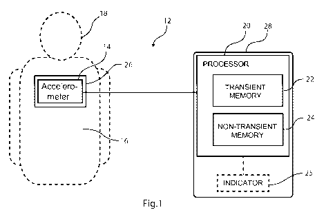
Fig.1 schematically illustrates an embodiment of a system
12 for quantifying the function of a beating heart, or more
specifically for determining an indication of heart failure.
The system 12 has an accelerometer 14 in the form of a
piezoelectric element that can be placed on the chest of a
person 18 and for measuring vibrations of the chest wall
caused by movements of the heart. A processor 20 is connected
with the accelerometer 14. The processor 20 has a transient
memory 22 which can store a signal received from the
accelerometer 14, and by which it can execute program code
instructions. The system 12 comprises a support 26 that
supports the accelerometer 14 and a housing 28 that
accommodates the processor 20. The system 12 also has a non-
transient memory 24 storing program code instructions for the
processor 20. For example, the system 12 as a whole can be an
integral part of a smart-phone, or all parts except the
accelerometer 20 and the support 26 can form part of a smart-
phone. In one embodiment, the accelerometer is an integrated
accelerometer of a smart-phone.
CA 03026972 20112-137
WO 2017/216374 PCT/EP2017/064834
17
In one embodiment of the system 12, it additionally has
an indicator 25 operatively connected with the processor 20.
The indicator 25 can, for example, have an LCD display, or
the like, that can display output information from the
processor 20, such as a number.
The program code instructions in the non-transient memory
24 cause the processor 20 to perform a method that is shown
in Fig.2. The accelerometer is placed on the chest of a
person and a signal is recorded. A plurality of segments is
then obtained 102, where each segments corresponds to a
heartbeat or a cardiac cycle. This is followed by an
alignment 108 and a filtering 114. Here, a band-pass filter
is employed having a lower cut-off frequency of approximately
0.1 Hz, and an upper cut-off frequency of approximately 200
Hz. Subsequently, a mean segment is determined 118 from the
plurality of segments.
With the mean segment formed, a temporal feature is
determined 120. The temporal feature in turn is used to
determine 122 a measure. Examples of temporal features and
measures are described below. Output information is then
provided 128 based on the determined measure. In one
embodiment, the output information is a number that is
displayed on the abovementioned indicator 25.
Further details of the method are shown in the flow chart
of Fig.3. The step of obtaining 102 the plurality of segments
includes the sub-steps of recording 104 the signal with the
accelerometer, and dividing 106 the recorded signal into the
plurality of segments, for example by a technique as
described in US 8235912 B2 and US 8469896 B2 relying on
audible components of the accelerometer signal. The audible
components are obtained by filtering the recorded signal.
In an alternative embodiment, an electrocardiography
(ECG) signal is acquired simultaneously to the accelerometer
signal, and the ECG signal is used for the segmentation of
the latter. For example, a segmentation as described in
Jensen et al. (Computing in Cardiology 2014; 41:29-32) can be
used.
CA 03026972 2018-12-07
WO 2017/216374 PCT/EP2017/064834
18
When obtaining 102 the plurality of segments, a method
similar to the method described in Jensen et al. is employed
to remove noisy segments. A high-pass filter with a lower
cut-off of 65 Hz is applied to the segments and the onset of
the first heart sound Si is then determined by a known
technique. Similarly, a high-pass filter with a lower cut-off
of 50 Hz is applied to the segments and the onset of the
second heart sound S2 is then determined by a known
technique. The segments are then aligned according to the
determined second heart sound S2. In alternative embodiment,
the first heart sound is used instead.
The mean segment is determined 116 by summing the aligned
segments to a single segment and dividing the resulting
signal by the number of segments in the sum.
Fig.4a shows a segment that has been subjected to the
above described band-pass filtering. The abscissa represents
an acceleration in g (ms-2) and the ordinate the time in
milliseconds (ms). Here, g is proportional to the voltage
from the accelerometer 14. The zero point of the ordinate
corresponds to the R peak in a simultaneously recorded
segment of an ECG signal. A number of temporal features are
indicated in Fig.4a, which are further described below.
Fig.4b shows a segment that has been subjected to a high-
pass filter with a lower cut-off of 50 Hz, as described
above. The abscissa represents the signal strength X (no
unit) and the ordinate the time in milliseconds (ms). The
latter has been aligned by the simultaneously recorded
segment of an ECG signal in the same manner as described in
relation to Fig.4a. The onset of the first heart sound (Si)
and the second heart sound (S2) are indicated in Fig.4b.
In the steps of determining 118 the first temporal
feature and determining 120 the second temporal feature 120
in the mean segment, the following temporal features are
identified in the mean segment: the mitral valve closure
(MC), isovolumic movement (MO), aortic valve opening (AO),
the rapid ventricular ejection (RE), the aortic valve closure
(AC), the mitral valve opening (MO), the rapid ventricular
filling (RF), and the atrial systole (AS).
CA 03026972 2018-12-07
WO 2017/216374 PCT/EP2017/064834
19
For example, with the first point in time determined to
be the onset of the first heart sound (Si), see Fig.4b, the
isovolumic movement (IM) is determined as the first local
minima (IM) subsequent to the first point in time, the mitral
valve closure (MC) is determined as the maximum negative
deviation (MC) prior to the first local minima (IM)
subsequent to the first point in time, the aortic valve
opening (AO) is determined as the global maxima subsequent to
the first point in time, and the rapid ventricular ejection
(RE) is determined as the global maxima (RE) subsequent to
the global minima (IC) subsequent to the global maxima (AO)
subsequent to the first point in time. For example, the first
point in time can be determined by a technology similar to
the technology described in US8235912 B2 and US 8469896 B2.
One measure that is determined is the amplitude or signal
strength of the above mentioned temporal features. For
example, the signal strengths of the following temporal
features can be determined, the aortic valve opening (AO),
the atrial systole (AS), the isometric contraction (IM), and
the rapid ventricular ejection (RE) of a heart cycle.
Another measure that is determined is based on the
locations in time, or positions on the abscissa of the
Fig.4a, of a first temporal feature and a second temporal
feature. The measure is then determined as the difference in
time between a first temporal feature and a second temporal
feature, wherein the measure is based on the determined
difference. The following measures can be determined, the
difference in time between the mitral valve closure (MC) and
the rapid ventricular ejection (RE), the difference in time
between the atrial systole (AS) and the mitral valve closure
(MC), the difference in time between the aortic valve closing
(AC) and the mitral valve opening (MO), the difference in
time between the aortic valve opening (AO) and the aortic
valve closing (AC), and the difference in time between the
mitral valve closure (MC) and the aortic valve opening (AO).
Output is then provided 128 in the form of values that
are displayed on an LCD display of the indicator 206, where
CA 03026972 20112-137
WO 2017/216374 PCT/EP2017/064834
the values represents the determined signal strengths and
differences in time in the examples above.
Fig.5 schematically illustrates an alternative embodiment
of a system for quantifying the function of a beating heart,
5 or more specifically for determining an indication of heart
failure. The system 12 is similar to the system described in
relation to Fig.1 and features having the same or related
functions have been given the same number indices. In
addition, the system has a microphone 30 in the form of a
10 transducer that can convert sound into an electrical signal.
The microphone 30 is supported by the support 26.
The program code instructions in the non-transient memory
24 correspond to those described in relation to Figs. 2 and
3, but with different steps for obtaining 102 the plurality
15 of segments, as illustrated in Fig.6. With the microphone
placed on the chest of the person, the program code
instructions additionally causes the processor 20 to operate
the microphone 30 to record 130 an audio signal with the
microphone 30 simultaneously to the signal being recorded 104
20 with the accelerometer 14. A plurality of second heart sounds
(S2) are then identified 132 in the audio signal. The
recorded signal is then divided 134 into the plurality of
segments based on the time correlation between the signal and
the audible signal, and the identified plurality of second
heart sounds (S2) in the audible signal to obtain the
plurality of segments. The identification of the second heart
sounds (S2) and the segmentation is based on the technologies
described in US 8235912 B2 and US 8469896 B2.
The subsequent alignment 108 is then also based on the
plurality of second heart sounds (S2) determined from the
audio signal.
Fig.7a illustrates an alternative embodiment of the
system 12 described in relation to Fig.1, with the only
difference that the support 26 forms part of the housing 28
such that the housing 28 covers at least a portion of the
accelerometer 14. In this embodiment, the housing 28 is
placed on the chest of a person, which means that the
accelerometer 14 is also placed on the chest of a person.
CA 03026972 2018-12-07
WO 2017/216374 PCT/EP2017/064834
21
Similarly, Fig.7b illustrates an alternative embodiment of
the system 12 described in relation to Fig. 5, with the only
difference that the support 26 forms part of the housing 28
such that the housing 28 covers at least a portion of the
accelerometer 14 and the microphone 30. In this embodiment,
the housing 28 is placed on the chest of a person, which
means that the accelerometer 14 and the microphone 30 are
also placed on the chest of the person.
Proof of concept
A custom lightweight 8 g piezoelectric accelerometer was
developed for acquisition of the SCG signals. The low weight
provides a better signal and the miniaturization allows for
the accelerometer to be incorporated in another device. The
accelerometer was used in a system as described above in
relation to Figs.1-4.
It should be noted that the system identifies AO and MO
and the resulting measures are not consistent. However,
despite this disadvantage, AO and MO were used, since they
have diagnostic importance.
The system was used on a first group of healthy subjects
and on a second group of heart failure (HF) subjects
undergoing pacemaker optimization. The majority of the heart
failure subjects suffered from diastolic dysfunction. As is
evident from Table 1 below, the amplitudes, or signal
strength, and differences in time, or time intervals, of the
temporal features provide a clear discrimination between
heart failure patients and the normal subjects included.
Measure Normal subjects HF subjects Classification
Mean (STD) Mean (STD) AUC
Amplitudes [mg] [mg]
AO 21.9 (13.1) 3.0 (2.2) 98.0%
AS 5.4 (2.5) 1.5 (0.9) 97.1%
IM -23.7 (14.1) -3.5 (3.5) 95.0%
RE 7.3 (4.1) 2.6 (2.5) 86.1%
Time intervals Ems] Ems]
CA 03026972 2018-12-07
WO 2017/216374 PCT/EP2017/064834
22
MC-RE 140.6 (26.2) 184.8 (27.8) 89.5%
AS-MC 65.6 (39.6) 137.9 (71.1) 83.4%
AC-MO 43.1 (13.3) 59.7 (24.8) 74.6%
AO-AC 296.6 (38.5) 311.7 (57.2) 63.2%
MC-AO 41.7 (19.7) 43.8 (31.8) 42.2%
Table 1 shows average values and classification performance
of the measures using the area under the receiving operating
curve (AUC). The measures are sorted in decreasing
classification performance.
Some of the measures of Table 1 were combined to improve
the classification further. This exemplified in Tables 2-4
Amplitude AUC
RE 86.1% (73,4-98.8%)
Time interval
MC-AC 63.8% (47-80.6%)
Combined score
RE + MC-AC 90.7% (80-100%)
Table 2 shows the combination of two measures, or three
temporal features.
_____________________________________________________________________
Amplitude AUC
RE 86.1% (73.4-98.8%)
Time intervals
AO-AC 63.2% (46.3-80%)
MC-AC 63.8% (47-80.6%)
Combined score
RE + AO-AC + MC-AC 92.8% (83.2-100%)
Table 3 shows the combination of three measures, or four
temporal features.
Amplitude AUC
RE 86.1% (73.4-98.8%)
Time intervals
AO-AC 63.2% (46.3-80%)
MC-AC 63.8% (47-80.6%)
AS-MC 83.4% (69.8-97%)
Combined score
CA 03026972 2018-12-07
WO 2017/216374 PCT/EP2017/064834
23
RE + AO-AC + MC-AC + AS-MC 95.1% (87.1-100%)
Table 4 shows the combination of four measures, or five
temporal features.
Feasible modifications of the Invention
The invention is not limited only to the embodiments
described above in relation to the drawings, which primarily
have an illustrative and exemplifying purpose. This patent
application is intended to cover all adjustments and variants
of the preferred embodiments described herein, thus the
present invention is defined by the wording of the appended
claims and the equivalents thereof. Thus, the equipment may
be modified in all kinds of ways within the scope of the
appended claims and the detailed description.