Note: Descriptions are shown in the official language in which they were submitted.
CA 03027135 2018-12-10
WO 2017/213508 PCT/NL2017/050385
Title: Flexible core for machine processing or production of composite
parts or materials
The invention is in the field of core materials for use in a closed
mold system in the production of fiber reinforced plastic materials. The
invention is particularly directed to core materials for use in autoclave
molding processes at elevated temperatures and pressures as well as to a
method for the preparation of the core materials.
Fiber-reinforced plastics are composite materials based on a
polymer resin such as an epoxy, vinylester or polyester and fibers such as
glass, carbon, aramid, or basalt. Fiber-reinforced plastics find applications
in a large variety of fields such as automotive, aviation, road signs,
windmills, boats, industrials parts and the like. The presence of the fibers
in
the polymer materials results in increased strength, stiffness, fatigue life,
fracture toughness, environmental resistance, increased temperature
stability, reduced weight and the like.
A core material can be incorporated in the fiber-reinforced plastics
in order to reduce the amount of resin required, reduce the weight of the
composite material and/or to increase the mechanical properties, such as the
bending stiffness. The use of core materials is known in the art.
Fiber-reinforced plastics comprising core materials are typically
manufactured manually (hand lay-up; spray-up) or by using closed mold
systems for e.g. vacuum-infusion processes, resin transfer molding (RTM) or
autoclave. Closed mold systems are preferred over the manual manufacture
in view of i.a. reproducibility of the material properties of the product,
improved surface properties, environmental consideration (less loss of resin)
and reduced overall manufacturing costs because of higher production
speed.
:30 To increase the production speed further, autoclave molding
processes may be used. Autoclave molding is generally a modification of
CA 03027135 2018-12-10
WO 2017/213508 PCT/NL2017/050385
2
commonly applied pressure-bag and vacuum-bag molding processes.
Pressure-bag and vacuum-bag molding processes typically involve filing a
mold with the reinforcement fibers, the resin and the core material, followed
by placing the filled mold in a bag and increasing or reducing the pressure
in the bag to force out possibly entrained air and/or excess resin. In
autoclave molding, the pressurized or vacuumed bag is placed in an
autoclave to cure the resin. Curing of the resin may take place under a
pressure up to about 8 bar and at temperature ranging from 80 C to about
170 C. Besides the increase production speed due to faster curing of the
resin, autoclave molding generally results in denser and essentially void-
free compositions.
Any used core material preferably meets a number of
requirements for a successful application. These requirements include i.a.
sufficient drapability (i.e. a sufficiently low bending stiffness), sufficient
flow
.. of resin through or into the core material, low resin uptake and a
sufficient
compression-resistance. Since fiber-reinforced plastic products are often
three-dimensionally shaped, the mold that is used typically has a contoured
surface corresponding to the shape of the article. Because the fibers and core
materials are placed onto this surface, it is preferred that the core material
is drap able such that they conform to the contoured surface of the mold. The
core materials are preferably also characterized by good compression-
resistance (i.e. related to the applied pressures during the application of
the
core material).
The compression-resistance is defined herein as the ability to
resist a force that tends to crush or buckle the core material. It is measured
by determining the height of the material before applying a pressure and
during applying a certain elevated pressure (e.g. 4 bar) perpendicular to the
plane of the core material. The compression-resistance at a certain pressure
is calculated as 100% x (height of the material at the elevated
pressure)/(height of the material at atmospheric pressure). The
3
compression-resistance thus indicates the remaining thickness and volume
of the core material and the amount of resin it replaces in the fiber-
reinforced plastic. To determine the compression-resistance a universal
testing machine, for instance a machine available from Zwick Roe11 AG
being equipped with heating plates can be used.
Core materials that meet the above requirements for applications
at about 1 bar pressure and room temperature (meaning that no external
heating is applied and the only heat is generated by the curing of the resin
itself) are described in EP1010793 and EP1542845.
However, the increased temperature
and pressures that are associated with autoclave molding processes or other
applications involving elevated pressures and temperatures, pose a
challenge for the currently available core materials, in particular for the
compression-resistance of the core materials. Given the advantages of
elevated pressures and temperatures in the production of fiber-reinforced
plastics, its is desirable to have a core material that is applicable under
such
conditions.
In a first aspect, the present invention is accordingly directed to a
core material, suitable for use in a closed mold system, based on at least one
fibrous web containing a foam-structure within the web, said foam-structure
being formed of a plurality of members that are separated from each other
by channels, wherein said core material has a compression-resistance of
greater than 40% at a pressure of 4 bar and at a temperature that is greater
than or equal to 80 C.
The compression-resistance typically decreases by an increase of
the temperature. For applications of the core material under both elevated
pressures and temperatures, it is preferred that the compression-resistance
remains sufficient under elevated temperature and does not decrease too
much. Although, some decrease in compression-resistance is typically
unavoidable, for a broad application of the core material it is preferable
that
Date Recue/Date Received 2020-09-23
CA 03027135 2018-12-10
WO 2017/213508 PCT/NL2017/050385
4
the compression-resistance of the core material remains sufficient at an
entire range of temperatures. For instance, it is preferred that the core
material has a compression-resistance of greater than 40% at a pressure of 4
bar and at any temperature in the range of 80-170 C, or for instance in the
range of 80-140 C.
In certain cases, in particular in cases wherein molding is
invariably carried out at a certain temperature, compression-resistance over
an entire range may not be required and it may be sufficient to have a core
material that meets the requirement at that a certain temperature.
In general, higher temperatures in autoclave molding processes
are advantageous in terms of curing and overall production times.
Accordingly, it is preferred that the compression-resistance of the core
material is greater than 40% at a pressure of 4 bar and a temperature that
is greater than or equal to 120 C, preferably greater than or equal to
140 C.
In preferred embodiments, the compression-resistance is greater
than 60 %, preferably greater than 80% at any of the above-mentioned
pressures and temperatures.
The compression-resistance of the core material of the present
invention is expressed above as a compression-resistance at a pressure of 4
bars. However, the compression-resistance of the core material may also be
expressed as a compression-resistance at pressures higher than 4 bars.
For instance, the core material may have a compression-
resistance greater than 30% at a pressure of 6 bar and at a temperature
that is greater than or equal to 80 C. Preferably, the compression-
resistance is greater than 40%, preferably greater than 50% at a pressure of
6 bar and at a temperature that is greater than or equal to 80 C. The core
material may also have a compression-resistance of greater than 30% at 8
and at a temperature that is greater than or equal to 80 C and/or have a
CA 03027135 2018-12-10
WO 2017/213508 PCT/NL2017/050385
compression-resistance of greater than 30% at 10 bar and at a temperature
that is greater than or equal to 80 C.
The compression-resistances at a higher pressure than 4 bars may
complement or substitute the compression-resistances expressed at a
5 pressure of 4 bar. Preferably, the compression-resistances at a higher
pressure than 4 bars complement the compression-resistances at a pressure
of 4 bar meaning that the core material have the compression-resistance at
4 bar as described above as well as the compression-resistance at 6, 8 and/or
bar as defined in the previous paragraph.
10 An additional advantage of compression-resistance of the present
core material, is that it may make the core material suitable for use in resin
transfer molding (RTM) methods to inject the resin in the mold. Pressures of
2 to 15 bar and sometimes even higher are typical pressures for use in RTM.
3-dimensional shapes may also be produced using techniques such as
vacuum infusion and "RTM Light", wherein RTM Light uses typical
pressures up to 2 or 3 bars. The core material can also be used in other
processes involving elevated pressures (e.g. up to 15 bar) and/or
temperatures (e.g. up to 200 C).
The present inventors have surprisingly found that the
compression-resistance under elevated pressures and temperatures of the
core materials can be increased by a number of measures, each contributing
to the compression-resistance of the core material. This enables an accurate
selection of the required compression-resistance, without unnecessarily
compromising the other requirements of the core materials such as
drapability, allowing fast flow of the resin through the core material or
choosing a level of these properties that suits the application or process.
One measure to obtain the compression-resistance of the present
invention, is the use of high-temperature expendable microspheres to obtain
the foam-structure. Expendable microspheres are known in the art and for
instance also described in the above-mentioned EP1010793 and EP1542845.
CA 03027135 2018-12-10
WO 2017/213508 PCT/NL2017/050385
The members form 'isles' within or upon the web, which members
are at least largely surrounded by channels, through which channels the
resin can flow. The channels may also function to allow the resin to
penetrate the core material since the channels are largely void. In addition,
the channels may assure a certain drapability. The channels are largely free
of web material or fibers, although some fiber material may be present to
provide sufficient consistency of the core material. Preferably, the material
content in the channels should be low enough to allow a sufficient
permeability to allow sufficient penetration of resin. The members can also
comprise microspheres or being formed thereof. The members are believed
to provide the compression-resistance of the core material.
The present inventors found that, in particular at pressures up to
about 9 bar at elevated temperatures (e.g. 80 C and higher), the
compression-resistance of the core material can be mainly attributed to the
presence of the microspheres in the members. In addition, the present
inventors have found that the microspheres used in known core materials
may not be sufficiently temperature resistance, viz, their contribution to the
compression-resistance decreases considerably at higher temperatures.
However, it was further found that microspheres having a high initial
temperature (also referred to as activation temperature) perform better in
this respect. Accordingly, the members comprise microspheres having an
activation temperature of at least 140 C, preferably between 150 and
180 C, more preferably between 155 and 175 C. Microspheres having an
even higher activation temperature such as up to 220 C may also be used.
Commercially available microspheres having an activation temperature of
between 195 and 215 C may thus also be suitable.
Expendable thermoplastic microspheres, e.g. of a thermoplastic
polymer based on an alkylmethacrylate, such as methyl methacrylate,
acetonitril (such as polyacetonitril (PAN)), vinilydene chloride or a
combination thereof are commercially available, e.g. as ExpancelTM by
CA 03027135 2018-12-10
WO 2017/213508 PCT/NL2017/050385
7
AKZO-NOBEL. Particularly good results have been obtained with
ExpancelTM microspheres of the type 980 DU 120, that are characterized by
an activation temperature (Tstart) of 158-173 C.
Additionally or alternatively to the use of the high temperature
microspheres, the compression-resistance of the present invention, may be
obtained by having a core material wherein said fibrous web is impregnated
with a thermosetting polymer. This means that the both the fibrous web at
the site of the members as well as at the site of the channels separating the
members is impregnated with the thermosetting polymers. The
impregnation of the fibrous web is typically carried out after the members
and the channels have been formed (vide infra) but it may, in addition or
alternatively, also be carried out before the members and the channels are
formed.
In the embodiments wherein the fibrous web is impregnated with
the thermosetting polymer, good compression-resistance is obtained over a
broad range of elevated pressures (e.g. up to 12 bar) and temperatures (e.g.
80-200 C).
The drapability of the impregnated core material is generally
slightly lower than an otherwise identical non-impregnated core material.
However, in certain applications of the core material, for instance in
applications comprising form-setting, the drapability of the core material
may not be a hard requirement. Form-setting is a process wherein a minorly
curved or straight composite structure is pre-formed and subsequently
reshaped, typically under pressure and/or elevated temperature, to a more
complex 3D structure. Although, the minor curvature or lack of curvature
may ease the requirement of drapability of the core material, it may¨e.g. for
a broad application of the core material¨nonetheless be beneficial to have
good drapability properties.
For particular applications wherein the high performance of
impregnated core materials associated with the impregnation is not fully
CA 03027135 2018-12-10
WO 2017/213508 PCT/NL2017/050385
8
required and the performance of non-impregnated core material suffices, it
may be preferable not to impregnate the core material with the
thermosetting polymer.
The thermosetting polymer preferably comprises a polyacrylate, a
acrylic copolymer and/or polycarboxylic acid that is thermoset with a polyol.
Alternatively or additionally a styrene maleic anhydride copolymer can also
be used. Good results have been obtained with polymers comprising a
polyacrylate.
Additionally or alternatively to the above-described measures,
good compression-resistance at elevated temperatures and pressures may
also be obtained by providing a core material having a higher surface area of
the members per total surface area of the core material when compared to
the known core materials. This generally means that the surface area of the
members is larger (i.e. the members are broader), while the surface area of
the channels is smaller (i.e. the channels are more narrow), compared to the
known core materials. However, since the flexibility and/or drap ability of
the material can be mainly attributed to the presence of the channels, the
channels are preferably not too narrow or non-existing in order to maintain
the desired flexibility and/or drap ability of the material.
The shape of the members and the surface area of the members
can influence the mechanical properties of a pre-preg product that
comprises the core material. In processes for the preparation of composite
articles and in particular in autoclave molding processes, pre-preg products
may be used. Pre-preg products are commonly products comprising the
reinforcement fibers and only partially cured (B-stage) resin.
In general, a larger surface area of the members can favorably
improve the bending stiffness of a laminate comprising the core material of
the present invention that is sandwiched between two pre-preg layers. For
instance, a hexagonal shape of the members of approximately 3 mm by 4
CA 03027135 2018-12-10
WO 2017/213508 PCT/NL2017/050385
9
mm, separated by small channels, (see for instance EP1010793), is favorable
over a random dot pattern as for instance described in EP1542845.
On the other hand, members that are shaped in a random dot
pattern, as for instance described in EP1542845, can be favorable to
improve shear strength of said laminate comprising the core material of the
present invention that is sandwiched between two pre-preg layers over said
hexagonal shape of the members.
Without wishing to be bound by theory, the present inventors
believe that above is explainable by the fact that the compression-resistant
members also contribute to the stiffness of the laminate. With increasing
the surface area of the members, the compression resistance as well as the
stiffness of the laminate may increase. This effect may be explained by the
following mechanical formulae:
S = P * L3 I (E * 1) and / = 1/12 * b * h3
wherein:
S = Deflection
P = Load
L = span length
E = Young's modulus
= area moment of inertia
b = width of area
h = distance of an element to the neutral line
The bending stiffness in the above formula can be defined as E * L
Less compression of the core results in more thickness (i.e. larger
h) which will result in a higher bending stiffness. Also, more available
pressure area provided by the members with respect to the total area, will
result in a higher residual thickness when the same pressure is applied.
CA 03027135 2018-12-10
WO 2017/213508 PCT/NL2017/050385
The channels between the members can provide opportunity for
the resin (e.g. the excess resin from a pre-preg) to connect the upper and
lower pre-preg layers of the sandwich laminate. As such, higher shear
strength can be obtained with the random dot pattern as described above.
5 This random dot pattern may provide more and more frequent resin
connections between the upper and lower pre-preg layers the laminate. The
degree of these connections can further relate to the free volume of a core.
The higher the free volume, the more resin flows into the core and connects
the layers of the laminate.
10 In case pre-preg products and layers are used, the amount of
available resin is limited. Accordingly, in order to prevent the transfer of
too
much resin from the pre-preg products into the free volume of the fibrous
web it is preferred that the free volume is not too large. Too much resin
being transferred may result in dry spots of the skin fibers, with negative
impact on appearance and mechanical properties of the laminate. Vice
versa, in order to prevent the amount of the above-described connections
between the pre-preg layers dropping below a certain critical threshold, the
surface area of the members should not be too large. In case, the amount of
said connection is too low, the laminate may become sensitive to
delamination when bending forces are applied. The preferred ratio of free
volume and surface area of the member typically depends on type of pre-
preg, resin and resin content.
The core materials as described in EP1010793 and EP1542845
may be prepared by screen printing processes as described therein.
However, using a mesh screen for screen printing as such to provide the
dimension of the members and the narrow channels in accordance with the
present invention is practically not feasible as the screen wires would
become too thin.
Surprisingly, the present inventors have found a method for the
preparation of the core material with a large member surface area to
CA 03027135 2018-12-10
WO 2017/213508 PCT/NL2017/050385
11
channel surface area without compromising the drap ability of the core
material. Said method comprises introducing unexpanded microspheres into
the fibrous web using at least one binder, followed by expanding the
introduced unexpanded microspheres while restricting the expansion of the
microspheres in the direction orthogonal to the plane of the core material.
It was found that the core material obtainable by the method
according to the present invention has particularly favorable compression-
resistance properties, without notably sacrificing the other above-described
requirements of the core material.
Without wishing to be bound by theory, the present inventors
believe that the improved compression-resistance of the core material
obtainable by the method according to the present invention can be
explained as follows.
In general, unexpended microspheres are expanded under the
influence of one or more blowing agents. The blowing agent has usually been
incorporated in the expandable microspheres. The presence of this blowing
agent is responsible for an expansion of the microspheres when a fibrous
web, comprising the micro-spheres, is cured. Thus, the microspheres are
pressed into the fibrous web in unexpanded form, for example by means of a
paste, such as a foam paste. The blowing agent may be a chemical or
physical blowing agent, such as azoclicarbonamide, isobutane, isopentane,
pentane, freon, iso-octane etcetera.
The screen printing methods as described in EP1010793 and
EP1542845, the expansion of the microspheres is not restricted in any
direction. As a result, the microspheres may theoretically expand in all
directions. However, in case the expansion of the microspheres in a certain
direction is restricted, the microspheres expand more in the other directions.
The expanded microsphere may be considered to be flattened, e.g. shaped as
oblate spheroids, while maintaining essentially the same volume compared
to spheres that are expanded in a non-restrictive manner. The present
CA 03027135 2018-12-10
WO 2017/213508 PCT/NL2017/050385
12
microspheres may thus expand more in the direction of the plane of the core
material (i.e. orthogonal to the direction of the restricted expansion).
Concomitantly, the members may become broader and the channels may
become more narrow upon expansion of the microspheres. This results in a
.. higher surface area of the members relative to the surface area of the
channels. To further aid expansion within the restricted orthogonal
direction to the plane of the core, one can increase the amount of binder-
microsphere mixture that is transferred into the web by the screen printing
process to a level that is higher than strictly needed to create the members.
.. In this way one can influence the density of the final material, which has
an
impact on its typical properties like compression-resistance.
Expanding the microspheres while restricting the expansion
preferably comprises heating under a pressure in the direction orthogonal to
the plane of the core material. The restriction of the expansion by heating
.. under pressure may for instance be carried out by using a plate press, a
double belt press or a calendar, or a combination thereof. The use of a
calendar is preferred since it enable a more accurate and precise control
over the final thickness of the core material. Accordingly, the heating under
a pressure preferably comprises calendaring, or calendaring with a
combination of said methods.
In a typical preparation process, the microspheres are introduced
by screen printing, followed by a drying step at e.g. about 100 C. In a next
step, the microsphere may be expanded and the binder may be cured at high
temperatures (e.g. about 200 C). In a preferred embodiment, this last step
comprises calendaring to restrict the microsphere in expanding in the
direction orthogonal to the plane of the core material.
Alternative or additionally to screen printing, the introduction of
the microspheres can also be carried out by impregnation, scattering or a
combination thereof.
CA 03027135 2018-12-10
WO 2017/213508 PCT/NL2017/050385
13
An advantage of the present invention is that a core material can
be provided that has a thickness of less than 1 mm. The core material may
for instance have a thickness of between 0.4 to 0.9 mm, or about 0.7 mm.
Previous processes without calendaring did not allow a
sufficiently accurate control over the thickness enough to enable the
preparation of thin core materials. The method of the present invention
however, in particular the method comprising calendaring, enables accurate
control over the thickness, e.g. up to the tenth of a millimeter. Core
materials having a thickness of less than 1 mm are preferred for application
in thin articles, e.g. composite panels for use in the automotive industry.
With the method of the present invention, a core material can be
provided having a lower free volume of the fibrous web compared to known
methods. The free volume is to be understood as the volume of the material
that can be accessed by resin. The remainder of the volume will be formed
by the members, some fibers and optionally the thermosetting polymer. A
lower free volume contributes to the compression-resistance of the core
material.
With known methods (e.g. those described in EP1010793 and
EP1542845) it is not possible to provide a low free volume without
undesirably reducing the drap ability and permeability of the core material
because a low free volume could only be obtained by increasing the size of
the members while maintaining the width of the channels¨which in these
known methods is bound to the minimal dimensions of the screen used in
the screen printing. However, the present invention may advantageously
provide more narrow channels such that a lower free volume can be
obtained while maintaining the other favorable properties of the core
material. Accordingly, the free volume of the present core material is
preferably less than 60%, preferably less than 40%, for instance about 20 to
40%.
CA 03027135 2018-12-10
WO 2017/213508 PCT/NL2017/050385
14
The unexpanded microspheres may be introduced as a blend with
the binder. Suitable binders in this regard are for instance lower alkyl
acrylate polymer, styrene-butadiene rubber, acrylonitrile polymer,
polyurethane, epoxy resins, polyvinyl chloride, polyvinylidene chloride, and
copolymers of vinylidene chloride with other monomers, polyvinyl acetate,
partially hydrolyzed polyvinyl acetate, polyvinyl alcohol, polyvinyl
pyrrolidone, polyester resins, and so forth. Optionally these binders can be
provided with acidic groups, for example by carboxylating the binders. A
suitable carboxylating agent is, for example, maleic anhydride. In addition,
the binder, paste-like composition optionally contains water, surfactants,
foam stabilizers, fillers and or thickeners, as has been described in
EP0190788.
It was found that the dry weight ratio of binder to microspheres is
of an influence to the compression-resistance of the core material, in
particular at higher pressures (e.g. above about 10 bar). It is preferable
that
the binder and the unexpanded microspheres are present in the blend in a
dry weight ratio of more than 12 to 1, preferably more than 14 to 1 and more
preferably more than 18 to 1.
The method according to the present invention may further
comprise a step of impregnating the fibrous web with a thermosetting
polymer followed by heating the impregnated fibrous web above the
thermosetting temperature of the thermosetting polymer. The impregnation
of the fibrous web is preferably carried out after the expansion of the
microspheres since the fibrous web is more flexible before the impregnation,
which facilitates the expansion of the microspheres.
The fibrous web to be used according to the invention will usually
be a non-woven, which may be reinforced, based on conventional fibers. The
manufacture of suitable non-wovens has for instance been described by Dr.
H. Jorder, "Textilien auf Vliesbasis" (D.V.R. Fachbuch, P. Kepper Verlag). It
CA 03027135 2018-12-10
WO 2017/213508 PCT/NL2017/050385
is also possible to use a combination of a non-woven fibrous web with a
reinforcing fabric, one within or on top of the other.
The fibers of the web are preferably selected from the group of
natural fibers, glass fibers, metal fibers, ceramic fibers or synthetic
fibers,
5 such as acrylic, polyethylene, polypropylene, polyester, polyamide
(aramide),
carbon or polypropylene fibers and combinations thereof. More preferably
the fibers are selected from the group of glass fibers, polyester fibers,
polyester-polyethylene bicomponent fibers and combinations thereof. Very
good results have been achieved with polyester fibers. Polyester fibers have
10 been found to have very good adherence with the resin and tend to have a
favorably low moisture content.
According to a very convenient method, the non-woven is based on
a combination of polyester fibers and polyethylene-polyester bicomponent
fibers (or other low temperature melting fibers or powders). These types of
15 webs have been thermally bonded by the bicomponent fibers. By heating
the
web to the initial expansion temperature of the microspheres, which is
above the melting point of the polyethylene bond, the web becomes loose and
will expand easily. After expansion, and curing the final material again has
its good bond, resulting in the advantageous combination of properties of the
invention. At the same time the web is very easy to handle at the initial
stages of the process, thanks to the thermal bonding. However, the above is
not limiting or excluding any other type of web bonding or formation for the
used non-woven fibrous web, known by those skilled in the art, for use in
the present invention.
Particular good results have been obtained in case the fibrous web
comprises a needle-punched non-woven, i.e. a non-woven that is obtained by
a needle-punch production process. Without wishing to be bound by theory,
it is believed that neeclle-punched non-\\ ovens are preferred over other
types
of non-wovens, for instance carded chembond non-wovens, because the
typical random fiber orientation and/or higher fiber content of needle-
CA 03027135 2018-12-10
WO 2017/213508 PCT/NL2017/050385
16
punched non-wovens (at comparable weight per square meter) result in
improved tensile strength of the core material. The improved tensile
strength is particularly observed in the cross-direction of the core material.
A homogeneous strength of the fibrous web and the core material (i.e.
similar strengths in multiple directions of the fibrous web) is generally
favorable in machine processing or production of composite parts.
An additional advantage of needle-punched non-wovens is that a
web binder is not required for the construction of the fibrous web. In
contrast, for carded chembond non-wovens a web binder is typically
required. The presence of a web binder is generally not preferred since this
binder may (partially) degrade at higher temperatures, for instance at the
higher temperature applied in the expansion step in accordance with the
present invention. The needle-punched non-woven is thus preferable since it
can advantageously be used at higher process temperatures in the
expansion step in accordance with the present invention.
An advantage of the core material of the present invention, is that
the material has good thickness relaxation, or spring back, after a pressure
load when the load is removed, in comparison with conventional core
materials. The improved thickness relaxation can be seen as an indication
that the members of the present core material are mostly still intact and
functional. In case thickness relaxation is low, as may be observed for
conventional core materials, the members will typically be more damaged
permanently.
In processes for the preparation of composite articles and in
particular in autoclave molding processes, pre-preg products may be used.
Pre-preg products are commonly products comprising the reinforcement
fibers and only partially cured (B-stage) resin. The present invention also
encompasses a pre-preg product comprising the above-described core
material a curable resin.
CA 03027135 2018-12-10
WO 2017/213508 PCT/NL2017/050385
17
A further aspect of the present invention encompasses a method
for the preparation of a shaped (fiber-reinforced plastic) article, said
method
comprising placing a mold that comprises the core material with a curable
resin, or a pre-preg product in an autoclave, followed by curing the curable
resin in the autoclave.
For the purpose of clarity and a concise description features are
described herein as part of the same or separate embodiments, however, it
will be appreciated that the scope of the invention may include
embodiments having combinations of all or some of the features described.
The invention can be illustrated with the following examples.
Example 1: high-temperature microspheres
A web was prepared consisting of about 80 wt.% polyester fibers
and 20 wt.% binder (acrylate).
A binder-microsphere blend was made by mixing 3 kg of high-
temperature expandable microspheres (ExpancelTM, AKZO-NOBEL) into 97
kg of acrylate binder. The dry solids content of the acrylate binder was
about 52 wt.% and the dry weight ratio binder to microspheres was about
14.8 to 1.
The binder-microsphere mixture was applied to the web by rotary
screen printing, wherein the mixture was pressed into the web. After
printing the web was dried at about 110 C and subsequently expanded to a
thickness of about 2 mm at a temperature of about 220 C. Simultaneously
the web was cured.
Example 2: impregnation with a thermosetting polymer
A web was prepared consisting of about 80 wt.% polyester fibers
and 20 wt.% binder (acrylate).
A binder-microsphere blend was made by mixing 5 kg of
.. expandable microspheres having an activation temperature of about 125 C
CA 03027135 2018-12-10
WO 2017/213508 PCT/NL2017/050385
18
(ExpancelTM, AKZO-NOBEL) into 95 kg of acrylate binder. The dry solids
content of the acrylate binderwas about 52 wt.% and the dry weight ratio
binder to microspheres was about 11.6 to 1.
The binder-microsphere mixture was applied to the web by rotary
screen printing, wherein the mixture was pressed into the web. After
printing the web was dried at about 110 C and subsequently expanded to a
thickness of about 1.5 mm at a temperature of 200 C. Simultaneously the
web was cured.
Next, the fibrous web was impregnated with a water-based
polyacrylic acid polyol mixture.
After impregnation, the thermosetting polymer was cured at a
temperature of about 150 C.
Example 3: high-temperature microspheres and
impregnation with a thermosetting polymer
A core material was prepared as describe in Example 1 and was
impregnated as described in Example 2 resulting in a material of about
1.7mm.
Example 4: high-temperature microspheres and
calendaring
A web was prepared consisting of 80 wt.% polyester fibers and 20
wt.% binder (acrylate).
A binder-microsphere blend was made by mixing 3 kg of high-
temperature expandable microspheres (ExpancelTM 980DU120, AKZO-
NOBEL) into 97 kg of acrylate binder. The dry solids content of the acrylate
binder was about 52 wt.% and the dry weight ratio binder to microspheres
was about 14.8 to 1.
The binder-microsphere mixture was applied to the web by rotary
screen printing, wherein the mixture was pressed into the web. After
CA 03027135 2018-12-10
WO 2017/213508 PCT/NL2017/050385
19
printing the web was dried at about 110 C and subsequently expanded at a
temperature of about 225 C by restricting the expansion using a plate press
to limit the thickness to about 1.8 mm. Simultaneously the web was cured.
Example 5: high-temperature microspheres and
calendaring
Example 4 was repeated, but now the microspheres were
expanded by restricting the expansion using a plate press to limit the
thickness to about 1.4 mm.
Example 6
Using a universal testing machine available from Zwick Roe11 AG
being equipped with heating plates, the compression-resistance of the core
materials obtained in Example 1-5 were analyzed at 80, 120 and 140 C. As
a comparative example, Soric XF2 core material obtainable from Lantor,
Veenendaal, the Netherlands was analyzed as well.
The results are provided in Figures 1, 2 and 3.
Example 7:
A web was used consisting of 100 wt.% polyester fibers, which was
bonded by needle-punching (i.e. a needle-punched non-woven).
A binder-microsphere blend was made by mixing 2.3 kg high
temperature expandable microspheres (ExpancelTM 980DU120, AKZO-
NOBEL) into 97.7 kg of acrylate binder. The dry solids content of the
acrylate binder was about 50 wt.% and the dry weight ratio binder to
microspheres was 21 to 1.
The binder-microsphere mixture was applied to the web by rotary
screen printing, wherein the mixture was pressed into the web. The screen
print pattern was designed as a hexagonal pattern, as described in
EP1010793.
CA 03027135 2018-12-10
WO 2017/213508 PCT/NL2017/050385
After printing, the web was dried at about 100 C and
subsequently expanded at a temperature of about 225 C while restricting
the expansion using a belt press and a calender to limit the thickness to
about 1.1mm. Simultaneously the web was cured.
5
Example 8
A web was used consisting of 100 wt.% polyester fibers, which was
bonded by needle-punching (i.e. a needle-punched non-woven).
A binder-microsphere blend was made by mixing 2,3 kg high
10 temperature expandable microspheres (ExpancelTM 980DU120, AKZO-
NOBEL) into 97,7 kg of acrylate binder. The dry solids content of the
acrylate binder was about 50 wt.% and the dry weight ratio binder to
microspheres was 21 to 1. The screen print pattern was designed as a
random dot pattern, as described in EP1542845
15 After printing, the web was dried at about 100 C and
subsequently expanded at a temperature of about 225 C while restricting
the expansion using a belt press and a calender to limit the thickness to
about 1.1mm. Simultaneously the web was cured.
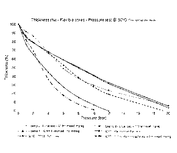
20 Example 9
Using a universal testing machine available from Zwick Roell AG
being equipped with heating plates, the compression resistance of the core
materials obtained in Example 7 and 8 were analyzed at 120 C and 140 C.
As a comparative example, Soric XF2 and TF1.5 core materials obtainable
from Lantor, Veenendaal, the Netherlands, were analyzed as well. The
results are provided in Figures 4 and 5.
Example 10:
A web was used consisting of 100 wt.% polyester fibers, which was
bonded by needle-punching.
CA 03027135 2018-12-10
WO 2017/213508 PCT/NL2017/050385
21
A binder-microsphere blend was made by mixing 2,7 kg high
temperature expandable microspheres (ExpancelTm 980DU120, AKZO-
NOBEL) into 97,3 kg of acrylate binder. The dry solids content of the
acrylate binder was about 50 wt.% and the dry weight ratio binder to
microspheres was 18 to 1. The screen print pattern was designed as a
random dot pattern, as described in EP1542845
After printing, the web was dried at about 100 C and
subsequently expanded at a temperature of about 225 C while restricting
the expansion using a belt press and a calender to limit the thickness to
about 1.1mm. Simultaneously the web was cured.
Using a universal testing machine available from Zwick Roell AG,
the compression resistance of the core material obtained was analyzed until
bars at room temperature. Directly after terminating the test at 20 bar,
and the pressure was released, the thickness of the test sample was
15 .. measured at 3 time intervals: at 5sec, at 1minute and after 5 minutes.
For
this a universal thickness meter, available from Mitutoyo Corp. was used,
equipped with a measuring stamp area of 38.5 cm2 and a standard load of
40.0 g/cm2. As a comparative example, Soric 0 XF2 and TF1.5 core
materials obtainable from Lantor, Veenendaal, the Netherlands, were
20 .. analyzed as well. The results are provided in Figure 6.