Note: Descriptions are shown in the official language in which they were submitted.
1
Method of Servicing an Aircraft Landing Gear Shock Absorbing Strut
Background
An aircraft landing gear shock absorbing strut is a structural assembly
arranged to carry
the weight of the aircraft when on the ground, and also absorb landing loads.
A major
component of an aircraft landing gear shock absorbing strut is therefore a
shock
absorber.
The shock absorber can be pressurised to achieve a particular shock absorber
extension
length, specific to a type of aircraft. This pressurisation level is
calculated using the
weight of the aircraft, the ambient temperature around the aircraft and static
design
spring curves.
A known type of shock absorber contains a generally incompressible liquid,
such as oil,
for damping purposes as well as an elastic gas, such as nitrogen or helium,
for spring
purposes.
In some cases the liquid and gas are separated within the shock absorber, for
example
by a separator piston.
In some other cases the liquid and gas are unseparated i.e. free to mix within
the shock
absorber. Such a shock absorber will be referred to as an "unseparated" shock
absorber.
The present inventors have devised a new method of servicing an unseparated
shock
absorber, which can enable the shock absorber to be serviced while the strut,
of which it
forms a part, is supporting the weight of the aircraft on the ground. The new
method
can also result in a faster service time and/or can be simpler than known
servicing
methods and/or increase the accuracy of servicing actions performed.
Summary
According to a first aspect of the invention, there is provided a method of
servicing an
unseparated shock absorber of an aircraft landing gear shock absorbing strut,
the shock
absorber including a sealed, variable volume chamber containing a liquid and a
gas, the
method comprising:
CA 3027628 2018-12-13
2
using a mixer to mix the liquid and the gas within the chamber until the
liquid is
uniformly saturated with the gas; and
subsequently performing one or more servicing actions.
Thus, the method according to the first aspect of the invention enables the
working fluid
within the shock absorber to be set in a known, equilibrium state for
servicing, where the
entire liquid volume is fully saturated with the gas and so the amount of gas
dissolved in
the liquid can be more easily determined. This is advantageous over known
methods in
which the liquid is in an unknown, partially saturated condition.
The steps of using the mixer and performing one or more servicing actions can
be
carried out while the shock absorbing strut is carrying the weight of the
aircraft,
optionally with the weight of the aircraft being fully supported by the shock
absorbing
strut throughout the process.
Thus, the method can result in a faster, simpler servicing procedure in
comparison to
known methods which require the aircraft to be jacked up to remove weight from
the
wheel(s) of the shock absorbing strut. The method can increase the accuracy of
servicing actions performed in comparison to a method not in accordance with
the
invention in which an unseparated shock absorber is serviced without jacking
the
aircraft.
Performing one or more servicing actions can comprise performing one or more
first
servicing measurements.
The one or more first servicing measurements can comprise measuring the
pressure
within the chamber.
The one or more first servicing measurements can comprise measuring the
temperature
within the chamber.
The one or more first servicing measurements can comprise measuring the length
of the
shock absorber.
After the step of performing one or more first servicing measurements, the
step of
performing one or more servicing actions can comprise a step of performing one
or more
first servicing operations.
CA 3027628 2018-12-13
3
The one or more first servicing operations can comprise adding gas to the
chamber or
removing gas from the chamber.
After the step of performing one or more first servicing measurements, the
step of
performing one or more servicing actions can comprise modifying the load
carried by
the shock absorber and performing one or more second servicing measurements.
The second servicing measurements can be the same types of servicing
measurements
as the first servicing measurements.
After the step of performing one or more second servicing measurements, the
step of
performing one or more servicing actions can comprise a step of performing one
or more
second servicing operations.
The one or more second servicing operations can comprise adding liquid to the
chamber
or removing liquid from the chamber.
The step of mixing using a mixer can comprise drawing liquid from a lower
region of the
chamber into a pumping unit and forcing the withdrawn liquid into an upper
region of the
chamber to spray the withdrawn liquid into the chamber.
Alternatively, the step of mixing using a mixer can comprise operating an
impeller
mounted for rotation within the chamber to mix the liquid and the gas within
the
chamber.
The liquid can comprise oil.
The gas can comprise nitrogen and/or helium.
According to a second aspect of the invention, there is provided aircraft
landing gear
shock absorbing strut servicing apparatus comprising:
an aircraft landing gear shock absorbing strut comprising an unseparated shock
absorber, the shock absorber including a sealed, variable volume chamber
containing a
liquid and a gas; and
a mixer provided in fluid communication with the inside of the chamber and
arranged to mix the liquid and the gas until the liquid is uniformly saturated
with the
gas.
CA 3027628 2018-12-13
4
Optional features of the first aspect can be applied to the second aspect in
an analogous
manner.
The mixer can comprise a pump device external to the shock absorber and
including a
first hose coupled to a first port through a lower end of the shock absorber
to as to
provide fluid communication with a lower region of the chamber and a second
hose
coupled to a second port through an upper end of the shock absorber to as to
provide
fluid communication with an upper region of the chamber. The pumping device
can be
arranged to draw liquid from chamber via the first hose and feed liquid back
into the
chamber via the second hose. The second port can be arranged with a plurality
of
apertures or flow diverting formations such as protrusions to cause the liquid
to be
sprayed into the chamber.
The mixer can comprise an impeller mounted for rotation within the chamber,
preferably
.. within a lower region of the chamber, and an electric motor arranged to
drive the
impeller, the motor being sealed within a liquid tight enclosure and either
being provided
with a dedicated battery or including a power cable extending from the motor
to a port
on the exterior of the shock absorber for coupling to an external power
supply.
Brief Description of the Drawings
Embodiments of the invention will now be described with reference to the
accompanying
drawings, in which:
Figure 1 is a diagram of an aircraft landing gear shock absorbing strut
servicing
apparatus according to an embodiment of the invention;
Figure 2 is a diagram of an aircraft landing gear shock absorbing strut
servicing
apparatus according to an embodiment of the invention;
Figure 3 is a flow chart of a method according to an embodiment of the
invention; and
Figure 4 is a flow chart of possible servicing actions within the method of
Figure 3.
Detailed Description
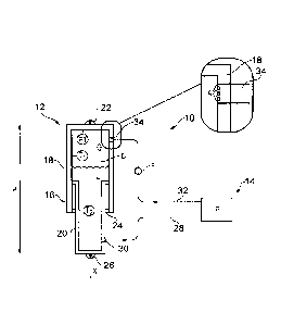
Figure 1 shows an aircraft landing gear shock absorbing strut servicing
apparatus
according to an embodiment of the invention generally at 10.
CA 3027628 2018-12-13
5
The servicing apparatus 10 includes an aircraft landing gear shock absorbing
strut 12
and a mixer 14.
The aircraft landing gear shock absorbing strut 12 can take any suitable form
including
an "unseparated" shock absorber 16, containing a liquid and a gas in fluid
communication with one another and not separated by a movable barrier such as
a
separator piston.
In this embodiment the shock absorber 16 defines the main structural load
bearing
assembly of the shock absorbing strut 12, with an upper cylinder 18 of the
shock
absorber 16 defining the main fitting for pivotally coupling to an airframe
(not shown)
via a main hinge 22. A sliding tube 20 is slidably mounted within the outer
cylinder 18
for linear movement along axis X between extending and compressed conditions.
The
cylinder 18 and sliding tube 20 are hollow so as to collectively define a
variable volume
chamber C containing a liquid L and a gas G. The chamber C is sealed by
dynamic seals
24. A lower end of the sliding tube 20 is provided with a ground contacting
assembly
coupling 26 for coupling to a wheel assembly, bogie beam or the like (not
shown).
For the following description the liquid L is oil and the gas G is nitrogen,
but other liquids
and gasses can be used.
Due to the effects of nitrogen dissolving and coming out of solution within an
unseparated shock absorber, determining the correct oil and nitrogen
quantities can be
difficult in a weight-on-wheels situation, where the shock absorbing strut is
carrying the
weight of the aircraft.
While the gas G and liquid L can remain substantially unmixed in an
unseparated shock
absorber, some gas will dissolve in the liquid. The variation of volume of the
liquid L due
changes in temperature and pressure is significantly smaller than the
variation of gas G
and can therefore be assumed to remain generally constant regardless of
temperature,
pressure and the amount of gas G dissolved in the liquid L. However, the
volume of gas
G can be relatively heavily dependent on temperature, pressure and the amount
of gas
G dissolved in the liquid L.
While the temperature and pressure of a gas can be readily determined or
estimated,
the amount of gas G dissolved in the liquid L cannot.
CA 3027628 2018-12-13
6
During landing, the increase in pressure and rapid flow of oil generated
causes nitrogen
to dissolve in the oil. However the amount of nitrogen that dissolves in the
oil can vary
depending on the landing conditions from a little to a moderate amount.
Depending on how much nitrogen has dissolved in the oil, the remaining shock
absorber
stroke along axis X will vary for the same shock absorber pressure, making any
assessment of the shock absorber length H potentially prone to error. As a
result,
nitrogen may be unnecessarily added during a service known servicing method.
This can
lead to an increased pressure in the shock absorber as nitrogen comes out of
solution
during flight, which in turn can compromise the landing performance of the
shock
absorber strut. In particular, it can increase the breakout load of the shock
absorber
strut, which can have a detrimental impact on 'weight on wheel' indication
performance.
In view of this, some landing gear are not permitted to be serviced with the
aircraft in
the weight on wheels condition. In order to service such a landing gear using
known
methods it is necessary to jack the aircraft, which can lead to a time
consuming and
difficult servicing procedure.
By way of a non-limiting overview, the present inventors have devised a
servicing
method in which the mixing device 14 is used to mix the oil and nitrogen until
the oil is
uniformly saturated with the nitrogen. The amount of nitrogen which is
dissolved in a
situation where the oil is saturated can be determined from empirical data and
so this
provides a known state from which to perform subsequent servicing actions such
as
measurements and operations.
In the illustrated example the mixing device 14 is a pump P located external
to the shock
absorber 16 and including a first hose 28 coupled to a first port 30 through a
lower end
of the shock absorber 16 to as to provide fluid communication with a lower
region of the
chamber C, where oil will gather due to gravity. The mixing device 14 also
includes a
second hose 32 coupled to a second port 34 through an upper end of the shock
absorber
so as to provide fluid communication with an upper region of the chamber,
where
nitrogen will settle. The pumping P is arranged to draw oil from chamber C via
the first
hose 28 and feed the oil back into the chamber C via the second hose 32.
Preferably the
second port 34 is arranged with a plurality of apertures A or flow diverting
formations
such as protrusions to cause the oil to be sprayed into the chamber. The hoses
28, 32
can each include a temperature transducer (not shown) to measure the
temperature of
fluid passing through the hoses 28, 32. The pump P can be configured to
circulate the
oil with a flow rate of, for example around 11 litres per minute with the pump
running at
CA 3027628 2018-12-13
7
50 Hz. An inverter drive (not shown) can be provided to enable the frequency
and thus
flow rate to be varied. The flow rate can be measured by a flow meter F. It is
preferred
that the pump is gear pump with positive displacement so that the speed of
rotation of
the pump motor enables the flow rate to be known.
Alternatively, the pump P can be located within the chamber C. In such
embodiments
the pump P and any driving motor can be provided within a sealed unit to
enable it to be
submerged and operate in a high pressure environment.
Measurements can be taken using, for example, a pressure transducer PT
arranged to
measure the fluid pressure within the chamber C and temperature transducers
Ti, T2
arranged respectively within the upper and lower regions of the chamber C to
measure
respectively the temperature of the nitrogen and the temperature of the oil.
An alternative embodiment of an aircraft landing gear shock absorbing strut
servicing
apparatus 50 is shown in Figure 2, which is similar to the apparatus 10 of
Figure 1
except that the mixer in this embodiment comprises an impeller 52 mounted via
a
bracket 54 for rotation within the chamber, preferably within a lower region
of the
chamber i.e. the region that contains oil. The impeller 22 can be driven by an
electric
motor 56, the motor being sealed within a liquid tight enclosure and either
being
provided with a dedicated battery or including a power cable extending from
the motor
to a port 58 on the exterior of the shock absorber for coupling to an external
power
supply V. When operated, the impeller 52 drives the oil and nitrogen in the
direction of
arrows A to mix the two.
In any embodiment, for a given shock absorber configuration the mixer can be
operated
for a length of time determined by simple testing to determine a time duration
that will
result in the liquid being uniformly saturated with the gas. In a constant
volume
condition the pressure will reduce until it reaches a stable pressure. In a
constant load
(pressure) condition the stroke of the shock absorber will reduce until it
reaches a
stabilised condition. Given the benefit of the present disclosure, it will be
apparent to
the skilled person that "uniformly saturated" can mean that the liquid
contains at least
90% of the mass of the gas which would be contained in a saturated state at
the same
temperature and pressure, i.e. is at least 90% saturated and preferably at
least 95%
and more preferably at least 99% saturated. A greater degree of saturation can
increase the accuracy of servicing actions performed.
CA 3027628 2018-12-13
8
Figure 3 is a flow chart illustrating a method 60 according to an embodiment
of the
invention.
At step 62 an unseparated shock absorber of an aircraft landing gear shock
absorbing
.. strut is provided. The shock absorber includes a sealed, variable volume
chamber
containing a liquid and a gas.
At step 64 a mixer is used to mix the liquid and the gas within the chamber
until the
liquid is uniformly saturated with the gas.
At step 66 one or more servicing actions are subsequently performed.
Steps 64 and 66 can be carried out while the shock absorbing strut is carrying
the
weight of the aircraft, optionally with the weight of the aircraft being fully
supported by
.. the shock absorbing strut throughout the process. Thus, the method can
result in a
faster, simpler servicing procedure in comparison to known methods which
require the
aircraft to be jacked up to remove weight from the wheel(s) of the shock
absorbing
strut.
Figure 4 is a flow chart illustrating servicing actions of step 66 in an
embodiment of the
invention.
At step 70 a plurality of first servicing measurements are made, which can
comprise
measuring the pressure within the chamber, measuring the temperature of the
oil and
nitrogen within the chamber and measuring the length of the shock absorber.
At step 72, gas can be added to the chamber, or removed from the chamber, as
necessitated by the first servicing measurements.
.. At step 74, the load carried by the shock absorber can be varied, for
example by jacking
the aircraft to reduce or remove the weight from wheels.
At step 76 a plurality of second servicing measurements are made, which can
comprise
measuring the pressure within the chamber, measuring the temperature of the
oil and
nitrogen within the chamber and measuring the length of the shock absorber.
CA 3027628 2018-12-13
9
At step 78, oil can be added to the chamber, or removed from the chamber, as
necessitated by the second servicing measurements in view of the first
servicing
measurements.
It will be appreciated however that other methods according to embodiments of
the
invention can comprise some of the steps, measurements and actions as
described
above.
Although the invention has been described above with reference to one or more
preferred embodiments, it will be appreciated that various changes or
modifications may
be made without departing from the scope of the invention as defined in the
appended
claims. The word "comprising" can mean "including" or "consisting of" and
therefore
does not exclude the presence of elements or steps other than those listed in
any claim
or the specification as a whole. The mere fact that certain measures are
recited in
mutually different dependent claims does not indicate that a combination of
these
measures cannot be used to advantage.
CA 3027628 2018-12-13