Note: Descriptions are shown in the official language in which they were submitted.
CANADA
PROVISIONAL PATENT APPLICATION
PIASETZKI NENNIGER KVAS LLP
File No.: ML001/DK
Title:
,
HOLLOW SCREENING CYLINDER AND ROTARY SCREENING
APPARATUS INCORPORATING SAME
Inventor(s):
Michael Langner
CA 3027802 2018-12-17
-1-
Title: HOLLOW SCREENING CYLINDER AND ROTARY SCREENING
APPARATUS INCORPORATING SAME
FIELD OF THE INVENTION
The present invention relates to the field of waste water treatment. More
particularly, the present invention relates to rotary screening apparatus for
separating solids from filtrate in an influent stream, and more particularly,
to a
rotary screening cylinder for a rotary screening apparatus.
BACKGROUND OF THE INVENTION
Various screening devices which incorporate rotatable screens are well known
for use in increasing the solid content of municipal sewage, sludge treatment,
and food processing. Conventional screening devices typically incorporate a
hollow screening cylinder, which has a cylindrical mesh screen supported by
cylindrical end frame members positioned adjacent each of the respective inlet
and discharge ends. Additionally, the hollow screening cylinder may include
cross-frame members joining the cylindrical end frame members on radially
opposite sides of the hollow screening cylinder, to provide additional
structural
support to the cylindrical mesh screen.
The hollow screening cylinder is rotatably mounted in a frame having metal
supporting wheels or a roller mechanism, and journalled for rotation about its
horizontal axis. For example, the metal supporting wheels may be configured
to engage U-shaped tracks provided in each of the cylindrical end frame
members. The hollow screening cylinder may be rotated by a chain drive unit,
including a drive motor which carries a drive sprocket, a drive chain, and a
driven sprocket which is secured to one of the cylindrical end frame members
CA 3027802 2018-12-17
-2-
supporting the cylindrical mesh screen. The drive sprocket on the drive motor
engages the drive chain which passes about the driven sprocket on one of the
cylindrical end frame members. When the drive motor is engaged, it rotates the
hollow screening cylinder about its axis on the metal supporting wheels or
roller
mechanism.
Influent to be screened is fed into the interior of the rotating hollow
screening
cylinder through an opening in the cylindrical end frame member of the hollow
screening cylinder at the inlet end. Once inside the rotating hollow screening
cylinder, the influent disperses over the screening surface of the rotating
hollow
screening cylinder. Filtrate from the influent then passes under gravity
through
openings in the screening surface, leaving behind solids which are too large
to
pass through the screening surface. The retained solids, which are too large
to pass through the screening surface, move along the interior of the rotating
hollow screening cylinder and outwardly therefrom through an opening at the
discharge end of the hollow screening cylinder.
To assist with moving the retained solids towards the discharge end and out
the
discharge opening, the interior of the hollow screening cylinder may be
provided
with a number of flights or diverter vanes at spaced locations, and configured
to move the retained solids toward the discharge end, as the hollow screening
cylinder rotates in one direction, and out of the discharge opening into a
collection hopper.
Conventional screening devices may also include a frustoconical end cover
attached to cylindrical end frame member at the discharge end of the hollow
screening cylinder, upstream of the collection hopper. The sloping sidewalls
of
the frustoconical end cover are configured to redirect influent which passes
outwardly from the discharge end back inside the rotating hollow screening
cylinder.
CA 3027802 2018-12-17
-3-
Examples of conventional screening devices include those disclosed in U.S.
Pat. Nos. 5,008,010, 5,607,587, and 5,733,450.
One problem associated with conventional screening devices is that the hollow
screening cylinder is subjected to a hostile environment, causing its
components, including the cylindrical end frame members, the cross-frame
members, and the cylindrical screen, to wear during use. Furthermore, influent
fed into the interior of the rotating hollow screening cylinder frequently has
an
alkaline, or an acidic pH level, which tends to corrode these components of
the
hollow screening cylinder, which can lead to failure of the screening device.
In
conventional screening devices, replacing worn or damaged components of the
hollow screening cylinder is difficult, and time consuming, leading to
significant
costs, in terms of labour and down time.
Another problem associated with conventional screening devices is that they
are typically sized, shaped, and configured to provide a predetermined
maximum influent processing capacity. As such, operators must know what
influent processing capacity they will require at the time of purchasing the
conventional screening device. Accordingly, it is typical for an operator to
purchase a screening device that is larger and more expensive than they
presently need, on the chance that they will require more influent processing
capacity at a later date. Alternately, an operator may purchase a first
screening
device based on current influent processing capacity requirements, and be
forced to purchase a second screening device if influent processing
requirements increase at a later date. In some cases, an operator may be
forced to sell or discard a screening device that is too small for current
processing requirements, and replace it with a larger screening device. As can
be appreciated the uncertainty concerning future influent processing capacity
requirements imposes costs on the operator of a conventional screening
device.
CA 3027802 2018-12-17
-4-
Accordingly, there is a continuing need for improvements in screening devices.
SUMMARY OF THE INVENTION
What is desired is an improved hollow screening cylinder, and a rotary
screening apparatus incorporating the same, which overcome at least some
of the problems associated with prior art devices.
According to an embodiment of the present invention, the hollow screening
cylinder has a plurality of screen sections removably attached to the outside
of a middle frame member. In this way, worn or damaged screen sections
may be accessible by a user from outside of the hollow screening cylinder,
so that the user may remove and replace the worn or damaged screen
sections from outside of the hollow screening cylinder, thereby avoiding a
step of removing the hollow cylinder from the frame of the rotary screening
apparatus when servicing the worn or damaged screens.
Preferably, the screens may be removably attached to the outside of the
middle frame member with fasteners. By way of example, the screens may
be removably attached to the outside of the middle frame member with
threaded pegs, or bolts extending outwardly from the middle frame member,
through the screen sections, and tightening threaded nuts thereon to hold
the screen sections in place. As another example, the screens may be
removably attached to the middle frame member by providing threaded
bores in the middle frame member and passing matching threaded fasteners
through the screens to anchor in the threaded bores to hold the screen
sections in place.
What is important is that the screen sections are removably attached to the
middle frame member from outside of the middle frame member, with
CA 3027802 2018-12-17
-5-
fasteners that can be fastened and unfastened by the user from outside of
the hollow screening cylinder.
Accordingly there is disclosed in accordance with one aspect of the present
invention, a rotary screening apparatus.
According to yet another aspect of the present invention, there is disclosed a
hollow screening cylinder.
According to yet another aspect of the present invention, there is disclosed a
method of making a rotary screening apparatus.
According to yet another aspect of the present invention, there is disclosed a
method of making a hollow screening cylinder.
According to yet another aspect of the present invention, there is disclosed a
method of replacing a worn or defective screen section in a hollow screening
cylinder.
BRIEF DESCRIPTION OF THE DRAWINGS
Reference will now be made to the preferred embodiments of the present
invention with reference, by way of example only, to the following drawings in
which:
Fig. 1 is a side view of a rotary screening apparatus having a hollow
screening cylinder, according to an embodiment of the present invention;
Fig. 2 is an exploded view of the hollow screening cylinder of Fig. 1,
showing an inlet end frame member, a middle frame member, a plurality of
screen sections, and an outlet end frame member;
CA 3027802 2018-12-17
-6-
Fig. 3 is a perspective view of the inlet end frame member of the hollow
screening cylinder of Fig. 1;
Fig. 4 is a front view of the inlet end frame member of Fig. 3, with the
screen securement members omitted for illustration purposes;
Fig. 5 is a side view of the inlet end frame member of Fig. 3;
Fig. 6 is a perspective view of a middle frame member of the hollow
screening cylinder of Fig. 1;
Fig. 7 is a front view of the middle frame member of Fig. 6;
Fig. 8 is a side view of the middle frame member of Fig. 6;
Fig. 9 is a perspective view of an outlet end frame member of the hollow
screening cylinder of Fig. 1;
Fig. 10 is a front view of the outlet end frame member of Fig. 9;
Fig. 11 is a side view of the outlet end frame member of Fig. 9;
Fig. 12 is a side view of the hollow screening cylinder of Fig. 1, with the
plurality of screen sections, and the screen securement members omitted for
illustration purposes;
Fig. 13 is a side view of a hollow screening cylinder featuring two middle
frame members joined together according to another embodiment of the
present invention, with the plurality of screen sections and the screen
securement members omitted for illustration purposes;
Fig. 14 is a side view of a hollow screening cylinder featuring three
middle frame members joined together according to yet another embodiment
of the present invention, with the plurality of screen sections and the screen
securement members omitted for illustration purposes;
Fig. 15 is a cross-sectional view of a detail of the hollow screening
cylinder of Fig. 1; and
Fig. 16 is a cross-sectional view of a detail of a hollow screening cylinder
according to another embodiment of the present invention.
DETAILED DESCRIPTION OF THE PREFERRED EMBODIMENTS
CA 3027802 2018-12-17
-7-
The present invention is described in more detail with reference to exemplary
embodiments thereof as shown in the appended drawing. While the present
invention is described below including preferred embodiments, it should be
understood that the present invention is not limited thereto. Those of
ordinary
skill in the art having access to the teachings herein will recognize
additional
implementations, modifications, and embodiments which are within the scope
of the present invention as disclosed and claimed herein.
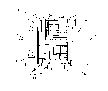
A rotary screening apparatus 10 according to an embodiment of the present
invention is shown in Fig. 1. As shown, the rotary screening apparatus 10 has
a hollow screening cylinder 12 which is rotatably supported on a frame 14, and
journalled for rotation about its rotational axis 16. The hollow screening
cylinder
12 has an inlet end 18, a discharge end 20, and a screen 22 positioned
between the inlet end 18 and the discharge end 20.
As best seen in Fig. 2, the hollow screening cylinder 12 is preferably
assembled
from four major components. The four major components include an inlet end
frame member 24, a middle frame member 26, a discharge end frame 28
member, and a plurality of screen sections 30. The inlet end frame member 24
and the discharge end frame member 28 may be attached to the middle frame
member 26 in any manner known in the art, including for example, with
fasteners 27 (i.e. nut and bolt, or rivets), or welding (not shown).
Preferably, the
screen 22 is formed from the plurality of screen sections 30 that are
removably
attached to the outside of the middle frame member 26 so that they may be
individually replaced by a user from outside of the hollow screening cylinder
12
when they become worn, or damaged, as discussed in more detail below.
Preferably, a gasket 23 is provided between each screen section 30, and the
middle frame member 26, to help prevent solids from bypassing the screen 22
through gaps between the screen sections 30 and the middle frame member
26. By way of example, the gasket 23 may be formed from a rubber, or rubber
CA 3027802 2018-12-17
-8-
like material, most preferably, a sponge rubber material. For clarity, only
one
such gasket 23 is illustrated in Fig. 2. However, it will be appreciated that
a
plurality of gaskets 23 may be provided between each screen section 30 and
the middle frame member 26. It is also contemplated that the gaskets 23 may
be omitted in other embodiments of the present invention. All such
embodiments are comprehended by the present invention.
The hollow screening cylinder 12 may be rotated in any manner known in the
art. By way of example only, the hollow screening cylinder 12 may be rotated
with a chain drive mechanism 32, as shown in Fig. 1. According to this
example, the chain drive mechanism 32 includes a drive motor 34 attached to
the frame 14. The drive motor 34 carries a drive sprocket 36 and is configured
to engage a chain 38 passing about a driven sprocket 40 attached to the inlet
end 18 of the hollow screening cylinder 12. Preferably, the hollow screening
cylinder 12 may be rotatably supported on rollers 42,42' attached to the frame
14. Preferably, the drive motor 34 may rotate the hollow screening cylinder 12
about its axis 16 journalled thereabout via the rollers 42 engaging respective
roller support surfaces 44 on the inlet and discharge end frame members 24,
28. Persons skilled in the art will appreciate that the chain drive mechanism
32
may be substituted by a belt drive mechanism comprising pulleys and belts in
stead of sprockets and chains, or a gear drive mechanism comprising gears.
Moreover, other known means for rotating the hollow screening cylinder 12 will
be apparent to the persons skilled in the art. All such embodiments are
comprehended by the present invention.
Influent to be screened is received through an opening 48 in the inlet end
frame
member 24 (best seen in Figs. 3 and 4) and directed into contact with the
radially inner surfaces of the screen 22. On contact with the screen 22,
filtrate
passes through the screen 22 and solid material to be collected which cannot
pass through the screen 22 is retained on the screen 22 and, ultimately
CA 3027802 2018-12-17
-9-
discharged out the discharge end 20. Thus, material that is captured by the
screen 22 is retained on the screen 22, and the rotation of the hollow
screening
cylinder 12 moves the solid material towards and out the discharge end 20.
Preferably, movement of the solid material towards and out the discharge end
20 may be accomplished by orienting the rotational axis 16 of the hollow
screening cylinder 12 so that it is tilted at a small angle from horizontal
towards
the discharge end 20 and/or by providing angled diverter vanes (not shown) on
the inside surfaces of the hollow screening cylinder 12.
With reference to Figs. 3-5, the inlet end frame member 24 has an end wall 46
defining opening 48. Preferably, the opening 48 may be sized to admit a
feedchute (not shown), or the like to feed influent into the hollow screening
cylinder 12. Extending from the end wall 46 is a side wall 50 that includes
the
roller support surface 44. Preferably, the side wall 50 also includes a rail
52 to
retain the hollow screening cylinder 12 in position on the roller 42. Roller
42 is
preferably provided with a groove 53 to match the rail 52, to prevent lateral
movement of the hollow screening cylinder. As shown, the support surface 44
of the hollow screening cylinder 12 rides on the shoulders 55 of the roller
42.
Preferably an attachment flange 54 may be provided to extend from the side
wall 50 for attaching the inlet end frame member 24 to the middle frame
member 26 with fasteners 27, such as nuts and bolts for example. Accordingly,
apertures 56 may preferably be provided on the attachment flange 54 to
facilitate the attachment with fasteners 27. Preferably, the inlet end frame
member 24 may be formed from steel having a gauge selected to provide the
necessary structural integrity to the hollow screening cylinder 12 depending
on
its intended use.
Good results have been obtained by sizing the opening 48 to have a 1 inch
larger radius than the feedchute. Accordingly, the opening 48 may have a
diameter of from 2 inches to 24 inches, or more or less depending on the
CA 3027802 2018-12-17
-10-
application, as will now be appreciated by persons skilled in the art.
The middle frame member 26 is shown in Figs. 6-8, according to an
embodiment of the present invention. Preferably, the middle frame member
comprises a pair of spaced apart rings 58. Crossmembers 60 are secured
between the rings 58, preferably by welding. However, any known means may
be used to secure the crossmembers 60, including using fasteners, rivets and
the like. Although six crossmembers 60 are shown in this example, more or
fewer may be used. All such embodiments are comprehended by the present
invention. As discussed in more detail below, the spaces 62 will be covered by
screen sections 30. What is important therefore is that the crossmembers 60
define spaces 62 therebetween which are sized to provide a desired area for
the influent to contact the removably attached screen sections 30, as well as
to
define attachment points for the screen sections 30. Preferably both rings 58
include an attachment flange 54 for attaching the middle frame member 26 to
the inlet end frame member 24 and the discharge end frame member 28 with
fasteners 27, such as nuts and bolts for example. Accordingly, apertures 56
may preferably be provided on the attachment flange 54 to facilitate the
attachment with fasteners 27. Preferably, the middle frame member 26 may be
formed from steel having a gauge selected to provide the necessary structural
integrity to the hollow screening cylinder 12 depending on its intended use.
Good results have been obtained by sizing the middle frame member 26 to
have a diameter of from 12 inches to 120 inches, or more or less depending on
the application, as will now be appreciated by persons skilled in the art.
With reference to Figs. 9-11, the discharge end frame member 28 has a side
wall 64 which defines a discharge opening 66. Preferably an outwardly flared
lip 68 may be provided on the side wall 64 to direct solid material moved out
from inside of the hollow screening cylindrical 12 into a collection hopper,
or the
CA 3027802 2018-12-17
-11-
like (not shown). Preferably the discharge end frame member 28 may include
an attachment flange 54 for attaching the discharge end frame member 28 to
the middle frame member 26 with fasteners 27, such as nuts and bolts for
example. Accordingly, apertures 56 may preferably be provided on the
attachment flange 54 to facilitate the attachment with fasteners 27.
Preferably,
the side wall 64 of the discharge end frame member 28 may also include the
roller support surface 44. Preferably, the discharge end frame member 28 may
be formed from steel having a gauge selected to provide the necessary
structural integrity to the hollow screening cylinder 12 depending on its
intended
use.
It will now be appreciated that the inlet end frame member 24, the middle
frame
member 26, and the discharge end frame member 28 may be attached together
with fasteners 27 as shown in Fig. 12, to form the portion of the hollow
screening cylindrical 12, to which the removably attachable screens 30 may be
attached.
Advantageously, two or more middle frame members 28 may be joined together
to increase the length of the hollow screening cylindrical 12, in discrete
increments based on the width of an individual middle frame member 28. For
example. As Fig. 13 shows a hollow screening cylinder 12 which is longer than
the hollow screening cylinder 12 shown in Fig. 12 by the width of one middle
frame member 28, because it includes two middle frame members 28.
Similarly, Fig. 14 shows a hollow screening cylinder 12 which is longer than
the
hollow screening cylinder 12 shown in Fig. 12 by the width of two middle frame
members 28, because it includes three frame members 28. Accordingly, it will
now be appreciated that the hollow screening cylinder 12 may be made with
one or more middle frame members 28 joined between the inlet end frame
member 24 and the discharge end frame member 28, based on the overall
CA 3027802 2018-12-17
-12-
desired length of the hollow screening cylinder screen 12.
Furthermore, it will be appreciated that the modular design of the hollow
screening cylinder 12 according to the present invention, will avoid the need
for
a manufacturer to stock hollow screening cylinders 12 in a range of different
lengths. Instead, a manufacturer or vendor will only need to stock the inlet
end
frame members 24, the middle frame members 26, the discharge end frame
members 28, and the screen sections 30 in predetermined sizes, and assemble
the components to the length required by the customer.
Moreover, the modular design will allow the user to increase the length of an
existing hollow screening cylinder 12 at a later date by simply adding one or
more additional middle frame members 26 to meet the need for additional
throughput. Advantageously the length of the rotary screening apparatus 10
may preferably be made to be adjustable to accommodate increasingly longer
hollow screening cylinder 12. For example, the frame 14 may be, made from
frame sections 15 that can be combined to build a longer frame 14 suitable for
supporting a lengthened hollow screening cylinder 12. As another example, the
frame 14 may be initially long enough to support a longer hollow screening
cylinder 12, and the rollers 42 may be configured to allow them to be spaced
apart further on the frame 14 to support a lengthened hollow screening
cylinder
12. All such embodiments are comprehended by the present invention.
Referring back Figs. 1 and 2, the screen sections 30 are shown as being
removably attached to the outside of the middle frame member 28 with
fasteners, to cover the spaces 62 between the crossmembers 60. Preferably,
the screen sections 30 may be made from steel wire woven into a mesh, a
perforated metal plate, wedge wire, or the like. Furthermore, the screen
sections 30 may be made from plastic. By way of example, the screen sections
30 may be removably attached to the outside of the middle frame member 26
CA 3027802 2018-12-17
-13-
with threaded pegs 68 extending outwardly from the middle frame member 26.
Accordingly, the screen sections 30 may preferably include a plurality of
matching apertures 70 to facilitate applying the screen sections 30 onto the
crossmembers 60 with the threaded pegs 68 passing through the apertures 70.
The screen sections 30 may then be secured on the middle frame member 26
by tightening threaded nuts 72 onto the threaded pegs 68 overtop of the screen
sections 30, as best seen in the detail of a cross-section of an embodiment of
the hollow screening cylinder 12 shown in Fig. 15.
As another example, the screen sections 20 may be removably attached to the
middle frame member 26 by providing threaded bores 74 in the middle frame
member 26 and passing matching threaded fasteners 76 through apertures 70
in the screen sections 30 to anchor in the threaded bores 74 and hold the
screen sections 30 in place. This is best seen in the detail of a cross-
section
of another embodiment of the hollow screening cylinder 12 shown in Fig. 16.
What is important is that the screen sections 30 are removably attached to the
middle frame member 26 from outside of the middle frame member 26, with
fasteners that can be fastened and unfastened by the user from outside of the
hollow screening cylinder 12.
While reference has been made to various preferred embodiments of the
invention other variations, implementations, modifications, alterations and
embodiments are comprehended by the broad scope of the appended claims.
Some of these have been discussed in detail in this specification and others
will
be apparent to those skilled in the art. Those of ordinary skill in the art
having
access to the teachings herein will recognize these additional variations,
implementations, modifications, alterations and embodiments, all of which are
within the scope of the present invention, which invention is limited only by
the
appended claims.
CA 3027802 2018-12-17