Note: Descriptions are shown in the official language in which they were submitted.
201701-5CA
MODULAR SUBSURFACE LIFT ENGINE
FIELD OF THE INVENTION
This invention relates in general to liquid hydrocarbon lift systems and, in
particular, to a modular subsurface lift engine adapted to directly or
indirectly lift
liquid hydrocarbons from a cased wellbore.
BACKGROUND OF THE INVENTION
Liquid hydrocarbon lift systems are well known and widely used to produce
fluids
from cased wellbores that lack sufficient natural well pressure to produce the
fluids without a mechanical lift system. The most commonly used mechanical
lift
systems are downhole pumps, which include sucker rod pumps that connect to a
bottom end of a production tubing, and insert pumps that are inserted into a
bottom end of a production tubing string. The sucker rod pumps and the insert
pumps are both driven by a "sucker rod string", which is a jointed slim rod
string
that reciprocates inside the production tubing string and connects the pump to
a
surface drive system. The surface drive system is typically a pumpjack,
sometimes referred to as a "nodding donkey" or a "rocking horse". While such
systems are both useful and reliable, they require a considerable amount of
material to construct, require a complex drive system, and can be expensive to
maintain. Furthermore, in highly deviated wells sucker rod strings tend to
fail due
to excessive wear in the curved sections of the wellbore. As well, downhole
pumps have to be located above the kickoff point in horizontal well bores to
prevent premature sucker rod failure and to keep the pumps in an upright
orientation in which they function optimally.
There therefore exists a need for a novel cased wellbore lift system that
overcomes many of the issues associated with prior art pumpjacks and
associated surface and subsurface pumping equipment.
- 1 -
CA 3027805 2018-12-17
SUMMARY OF THE INVENTION
It is therefore an object of the invention to provide a modular subsurface
lift engine
adapted to be used to produce fluids from a cased wellbore.
The invention therefore provides a modular subsurface lift engine, comprising:
an upper valve housing with an upper valve seat and an upper valve for
controlling a flow of produced fluid hydrocarbons through the subsurface lift
engine during a down-stroke thereof; an upper crossover sleeve connected to a
bottom end of the upper valve housing; an upper transition sleeve connected to
a bottom end of the upper crossover sleeve; an upper crossover tube connected
to an upper travel limiter that reciprocates within the upper transition
sleeve, the
upper crossover tube extending through a central passage in a bottom of the
upper transition sleeve; at least one subsurface lift engine module connected
to
a bottom end of the upper transition sleeve, respectively comprising a modular
cylinder sleeve, a modular cylinder piston that reciprocates within the
modular
cylinder sleeve, and a modular cylinder tube connected to a lower side of the
modular cylinder piston and extending through a passage in a modular cylinder
sleeve bottom wall of the modular cylinder sleeve; and a lower crossover
sleeve
adapted to connect to a production packer that isolates an annulus of the
cased
well bore surrounding the modular subsurface lift engine from an annulus of a
cased hydrocarbon well below the production packer.
The invention further provides a modular subsurface lift engine, comprising:
an
upper valve housing adapted to connect to a production tubing supported by a
wellhead of a cased well bore, the upper valve housing having an upper valve
seat and an upper valve for controlling a flow of produced fluid through the
subsurface lift engine during a down-stroke thereof; an upper crossover sleeve
connected to a bottom end of the upper valve housing; an upper transition
sleeve
connected to a bottom end of the upper crossover sleeve, the upper transition
sleeve having an upper crossover tube that is connected to a bottom of a
transition travel limiter, the crossover sleeve extending through a central
passage
in a bottom of the upper transition sleeve; at least one subsurface lift
engine
module connected to a bottom end of the upper transition sleeve and comprising
- 2 -
CA 3027805 2018-12-17
a modular cylinder sleeve, a modular cylinder piston that reciprocates within
the
modular cylinder sleeve, and a modular cylinder tube connected to a lower side
of the modular cylinder piston and extending through a passage in a modular
cylinder sleeve bottom wall of the modular cylinder sleeve; and a lower
crossover
sleeve having a lower valve housing with a lower valve seat and a lower valve
for
controlling a flow of produced fluids through the subsurface lift engine
during an
up-stroke thereof, the lower crossover sleeve being adapted to connect to a
production packer that isolates an annulus of the cased well bore surrounding
the
modular subsurface lift engine from an annulus of the cased well bore below
the
production packer.
The invention yet further provides a modular subsurface lift engine,
comprising:
at least one subsurface lift engine module adapted to be connected end-to-end
to other subsurface lift engine modules, each subsurface lift engine module
comprising: a modular cylinder sleeve having an open top end, a cylinder
sleeve
bottom wall with a central passage therein, and at least two cylinder sleeve
ports
adjacent the cylinder sleeve bottom wall to provide fluid communication
through
the modular cylinder sleeve with a modular cylinder lift chamber; a modular
cylinder piston with a modular piston seal that provides a high-pressure fluid
seal
between an inner wall of the modular cylinder sleeve and the modular cylinder
piston, the modular cylinder piston having an upper travel limiter and a lower
travel limiter to limit travel of the modular cylinder piston in the modular
cylinder
sleeve; a modular cylinder tube connected to the bottom travel limiter of the
modular cylinder piston and extending through a high pressure fluid seal in
the
central passage in the modular cylinder bottom wall, the modular cylinder tube
having at least two modular cylinder tube ports that provide fluid
communication
through a sidewall of the modular cylinder tube with a modular cylinder pump
chamber above the modular cylinder piston in an adjacent lower modular
cylinder
sleeve; an upper valve housing adapted to connect a production tubing
supported
by a wellhead of a cased well bore, the upper valve housing having an upper
valve seat and an upper valve for controlling a flow of produced fluids
through the
subsurface lift engine during a down-stroke thereof; an upper crossover sleeve
connected to a bottom end of the upper valve housing; an upper transition
sleeve
- 3 --
CA 3027805 2018-12-17
connected to a bottom end of the upper crossover sleeve, the upper transition
sleeve having a bottom end connected to the at least one lift engine module,
and
further having an upper crossover tube that is connected to a bottom end of an
upper transition travel limiter that reciprocates within the upper transition
sleeve,
the upper crossover tube extending through a central passage in a bottom of
the
upper transition sleeve; and a lower crossover sleeve having a lower valve
housing with a lower valve seat and a lower valve for controlling a flow of
produced fluid hydrocarbons through the subsurface lift engine during an up-
stroke thereof, the lower crossover sleeve being adapted to connect to a
production packer that isolates the subsurface lift engine from an annulus of
the
cased well bore below it, the production packer supporting a production tubing
that extends downwardly through the cased hydrocarbon well to fluids in the
cased well bore.
BRIEF DESCRIPTION OF THE DRAWINGS
Having thus generally described the nature of the invention, reference will
now
be made to the accompanying drawings, in which:
FIG. la is a cross-sectional view of an embodiment of a modular subsurface
lift
engine in accordance with the invention configured to directly produce fluids
from
a cased well bore, shown in an installed condition in the cased wellbore
equipped
with a production wellhead;
FIG. lb is the cross-sectional view of the embodiment of the modular
subsurface
lift engine shown in FIG. la, enlarged to more clearly illustrate the elements
of
the subsurface lift engine;
FIG. 2 is a schematic view of one embodiment of surface equipment used to
drive
the modular subsurface lift engine shown in FIGs. la and lb and 5;
FIG. 3a is a cross-sectional view of the modular subsurface lift engine shown
in
FIGs. la and lb in an up-stroke condition;
- 4 -
CA 3027805 2018-12-17
FIG. 3b is a cross-sectional view of the modular subsurface lift engine shown
in
FIGs. la and lb in a top-of-stroke condition;
FIG. 4a is a cross-sectional view of the modular subsurface lift engine shown
in
FIGs. la and lb in a down-stroke condition;
FIG. 4b is a cross-sectional view of the modular subsurface lift engine shown
in
FIGs. la and lb in a bottom-of-stroke condition;
Fig. 5 is a cross-sectional view of one embodiment of a modular subsurface
lift
engine configured to indirectly produce hydrocarbons from a cased well bore.
FIG. 6 is a cross-sectional view of another embodiment of the modular
subsurface
lift engine in accordance with the invention configured to directly produce
fluids
from a cased well bore, shown in an installed condition in the cased wellbore
equipped with a production wellhead; and
FIG. 7 is a cross-sectional view of the embodiment of the modular subsurface
lift
engine installed in a horizontal wellbore.
DETAILED DESCRIPTION OF THE PREFERRED EMBODIMENTS
The invention provides a modular subsurface lift engine adapted to directly or
indirectly produce fluids from a cased wellbore. Subsurface lift engine
modules
are respectively connected end-to-end to provide a lift capacity required to
lift the
fluids from the cased wellbore. The number of lift engine modules required for
a
particular installation depends on any one or more of several factors. In the
case
of directly lifting the fluid from the wellbore, those factors may include: a
viscosity
of the fluids; a vertical lift requirement; a diameter of the wellbore
production
casing; a diameter of the wellbore production tubing; and, a desired rate of
production. In the case of indirectly lifting the fluids from the cased
wellbore, the
subsurface lift engine may be connected to a downhole reciprocal pump, such as
a tubing pump or an insert pump, using a subsurface sucker rod string and the
factors determining the number of lift engine modules may include: a viscosity
of
the fluids; a vertical lift requirement; a diameter of the wellbore production
casing;
- 5 -
CA 3027805 2018-12-17
a diameter of the wellbore production tubing; a desired rate of production; a
weight of the sucker rod string; and, power requirements of the driven pump.
In the embodiment of the modular lift engine used to directly lift liquid
hydrocarbons from a wellbore, an upper valve housing connects the
interconnected lift engine modules to a production tubing joint suspended from
a
production wellhead. An upper valve is housed in the upper valve housing. The
upper valve may be any one of a ball valve, a check valve or a flapper valve.
The
upper valve prevents the backflow of lifted fluids during a downstroke of the
lift
engine. The upper valve housing is mounted to a top of an upper crossover
sleeve. In one embodiment the upper crossover sleeve is elongated and a
downstroke spring is inserted between a top end of the upper crossover sleeve
and an upper transition travel limiter. The downstroke spring constantly urges
the
modular subsurface lift engine to a bottom-of-stroke condition to provide a
positive downstroke when the modular subsurface lift engine is installed in a
highly deviated wellbore, a horizontal wellbore, is used to produce very
viscous
fluid, or is used to provide a very long vertical lift. An upper transition
sleeve
connected to a bottom of the upper crossover sleeve supports the
interconnected
lift engine modules.
A lower crossover sleeve connects the interconnected lift engine modules to a
production packer that isolates the modular subsurface lift engine from the
cased
wellbore below the production packer. A production tubing string is connected
to
a lower end of the production packer. The production tubing string extends
down
through the cased wellbore to the fluids to be produced from the cased well
bore.
Each lift engine module includes a modular cylinder sleeve having an open top
end and a modular cylinder sleeve bottom wall that connects the modular
cylinder
sleeve to a lift engine module below it. Each modular cylinder sleeve bottom
wall
has a central opening that accommodates a modular cylinder tube. A lower end
of each modular cylinder sleeve includes at least two modular cylinder sleeve
ports that provide fluid communication between an annulus of the cased well
bore
and a lift chamber of the modular cylinder sleeve. Each modular cylinder
sleeve
houses a modular cylinder piston having a piston seal that provides a high
- 6 -
CA 3027805 2018-12-17
pressure fluid seal between the modular cylinder piston and an inner wall of
the
modular cylinder sleeve. Each modular cylinder piston has a top travel limiter
that
limits piston travel during an up-stroke of the subsurface lift engine. Each
modular
cylinder piston also has a bottom travel limiter that limits the piston travel
during
a down-stroke of the cylinder piston. The bottom travel limiter prevents the
cylinder piston from occluding the modular cylinder sleeve ports at the bottom
of
a down-stroke of the subsurface lift engine. A modular cylinder tube is
threadedly
connected to a lower end of each piston lower travel limiter and a top end of
a
piston upper travel limiter of an adjacent lower module. The modular cylinder
tubes provide an uninterrupted fluid path through the interconnected cylinder
modules. Each modular cylinder tube has at least two modular cylinder tube
ports
that provide fluid communication with a modular cylinder pump chamber above
the modular cylinder piston of each subsurface lift engine module. The piston
upper travel limiters prevent the modular cylinder tube ports from reaching a
high-
pressure fluid seal in the bottom wall of an adjacent lift engine module above
it.
The lower crossover sleeve includes a lower valve housing with a lower valve
seat and a lower valve that controls fluid flow through the subsurface lift
engine
modules during an up-stroke of the subsurface lift engine. The lower valve may
be any one of a ball valve, a check valve or a flapper valve.
The subsurface lift engine is driven by surface equipment assembled using
components well known in the art. In one embodiment a high-pressure fluid pump
pumps a lift fluid from a lift fluid reservoir. The lift fluid may be any
stable, non-
corrosive fluid such as, for example, corrosion inhibited water or a light oil
such
as diesel fuel, kerosene, hydraulic fluid, or the like. Lift fluid is supplied
to the
high-pressure pump through a lift fluid supply line. Lift fluid exits the high-
pressure
fluid pump via a pump pressure line to a pump pressure valve, for example a
solenoid-controlled valve, that selectively routes the lift fluid thorough the
lift fluid
pressure line to the annulus of the hydrocarbon well isolated by the
production
packer, or to a lift fluid pressure bypass line connected to the lift fluid
reservoir.
The annulus of the hydrocarbon well is also connected to a lift fluid dump
line,
- 7 -
CA 3027805 2018-12-17
which is in turn connected to the lift fluid reservoir. A dump fluid valve
controls
flow through the lift fluid dump line.
In operation, the high-pressure pump continuously pumps the lift fluid at a
predetermined pump rate. During an upstroke of the subsurface lift engine, the
solenoid-controlled valve in the lift fluid pressure line is open and the lift
fluid dump
valve in the lift fluid dump line is closed. The lift fluid therefore flows
into the
isolated annulus of the hydrocarbon well and through the modular cylinder
sleeve
ports into the respective modular cylinder lift chambers, urging the
respective
modular cylinder pistons upwardly. The upward movement of the modular
cylinder pistons forces produced fluid out of the modular cylinder produced
fluid
chambers through the modular cylinder tube ports, up through the respective
modular cylinder tubes to the production tubing in the wellhead, and out
through
a hydrocarbon production pipe to a hydrocarbon production reservoir, which may
be a tank, a pipeline, or the like. When the modular cylinder piston upper
travel
limiters contact the modular cylinder bottom wall of an adjacent lift engine
module,
a pressure spike occurs in the lift fluid. The pressure spike is sensed by a
pressure sensor that trips the lift fluid dump valve to open the lift fluid
dump line
and simultaneously trips the pump pressure line control valve to shift to
reroute
the lift fluid through the lift fluid bypass line to the lift fluid reservoir.
These valve
movements drain lift fluid pressure from the subsurface lift engine and the
annulus of the wellbore, and the subsurface lift engine down-strokes under its
own weight and, in one embodiment, the pressure of the downstroke spring. The
down-stroke closes the upper valve and opens the lower valve as the modular
cylinder pistons downward movements create suction in the respective modular
cylinder produced fluid chambers, which sucks produced fluid up into the
respective modular cylinder produced fluid chambers. When the pressure sensor
senses an absence of fluid pressure in the dump fluid line, the lift fluid
dump valve
is closed and the lift fluid bypass valve is shifted to reroute the lift fluid
from the
lift fluid bypass line to the lift fluid pressure line and another up-stroke
commences. During the up-stroke, the subsurface lift engine lower valve is
closed
and the subsurface lift engine upper valve opens as the produced fluids flow
from
- 8 -
CA 3027805 2018-12-17
the modular cylinder produced fluid chambers to the hydrocarbon reservoir, as
described above.
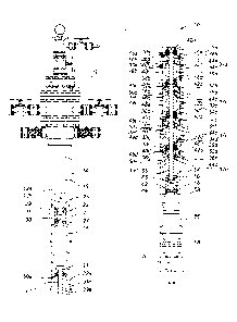
Part No. Part Descl notion
Modular subsurface lift engine
_ 10a Subsurface lift engine (indirect production configuration)
10b Subsurface lift engine (downstroke spring assist)
12 Wellhead
14 Production casing
16 Production tubing pup joint
18 Upper crossover sleeve
18b Elongated upper crossover sleeve
Upper transition sleeve
21 Upper transition travel limiter
22 Upper valve housing
23 Upper crossover tube
24 Upper valve seat
26 Upper transition sleeve cap
28 Upper valve fluid seal
Upper ball valve
31 Upper valve limiter
32a-32d Subsurface lift engine modules
34a-34d Modular cylinder sleeves
35a-35d Modular cylinder sleeve bottom walls
36a-36h Modular cylinder sleeve ports
37a-37d Modular cylinder sleeve bottom wall passage
38a-38d Modular cylinder pistons
39a-39d Modular cylinder sleeve inner walls
40a-40d Modular cylinder piston seals
42a-42d Piston upper travel limiters
44a-44d Piston lower travel limiters
45a-45d Modular cylinder lift chambers
46b-46d Modular cylinder tubes
48c-48h Modular cylinder tube ports
49b-49d Modular cylinder produced fluid chambers
50a-50d Modular cylinder tube upper seals
52a-52d Modular cylinder tube lower seals
54 Lower crossover sleeve
55 Lower crossover tube
55a Lower crossover tube (indirect production configuration)
56 Lower valve housing
58 Lower valve seat
60 Lower valve seal cap
62 Lower valve fluid seal
- 9 -
CA 3027805 2018-12-17
64 Lower ball valve
65 Lower valve limiter
66 Production packer
68 Production packer slips
70 Production tubing string
72 Sucker rod string
74 Downhole pump
75a,75a Lower crossover tube ports
76 Lower crossover tube thread
100 Surface equipment
102 Fluid pump
104 Lift fluid reservoir
106 Lift fluid supply line
108a-b Lift fluid pressure line
110 Pump pressure line control valve
112 Lift fluid bypass line
114a-b Lift fluid dump line
116 Lift fluid dump valve
117 Lift fluid pressure sensor
118 Solenoid control circuit
120 Hydrocarbon production pipe
122 Hydrocarbon reservoir
124 Lift fluid
126 Produced fluid
128 Isolated well bore annulus
130 Downstroke spring
FIG. la is a cross-sectional view of one embodiment of a modular subsurface
lift
engine 10 in accordance with the invention, configured to directly produce
hydrocarbons from a cased well bore 14. The modular subsurface lift engine 10
is shown in an installed condition in the production casing 14 of a cased well
bore,
which is equipped with a production wellhead 12. Surface components of the
cased well bore, such as the conductor, etc. are not shown. A top end of the
modular subsurface lift engine 10 is connected to the wellhead 12 by a
production
tubing "pup joint" 16 in a manner well known in the art. A bottom end of the
modular subsurface lift engine 10 is connected to a production packer 66,
which
is well known in the art. The production packer 66 provides a high-pressure
fluid
seal to isolate an annulus of the production casing 14 around the modular
subsurface lift engine 10 from an annulus of the production casing 14 below
the
production packer 14, the purpose of which will be explained in detail below
with
- 10 -
CA 3027805 2018-12-17
reference to FIGs. lb and 2. The production packer 66 is supported in the
production casing 14 by production packer slips 68, in a manner also well
understood in the art. A production tubing string 70, which extends down to a
production zone of the cased well bore, is connected to a downhole end of the
production packer 66.
FIG. lb is the cross-sectional view of the embodiment of the modular
subsurface
lift engine 10 shown in FIG. la, enlarged to more clearly illustrate the
elements
of the modular subsurface lift engine 10. The modular subsurface lift engine
10
includes an upper valve housing 22 connected to the production tubing pup
joint
16. An upper valve seat 24 is connected to a bottom end of the upper valve
housing 22. An upper valve housing cap 26 is connected to a top end of the
upper
valve housing 22. The upper valve housing cap 26 supports an upper valve fluid
seal 28, which provides a high-pressure fluid seal between the production
tubing
pup joint 16 and the upper valve housing 22. The upper valve seat 24 supports
an upper valve, which in this embodiment is an upper ball valve 30, although
the
upper valve may be a flapper valve or a check valve, both of which are well
known
in the art. Upward travel of the upper ball valve 30 is restrained by an upper
valve
limiter 31, which is only required when the upper valve is the upper ball
valve 30.
A bottom end of the upper valve housing 22 is connected to an upper crossover
sleeve 18. An upper transition sleeve 20 is connected to a bottom end of the
upper crossover sleeve 18. The upper transition sleeve 20 receives an upper
transition travel limiter 21 connected to an upper crossover tube 23.
Connected to a bottom end of the upper transition sleeve 20 is a first
subsurface
lift engine module 32a. Each subsurface lift engine module 32a-32d includes a
modular cylinder sleeve 34a-34d, which has a modular cylinder sleeve bottom
wall 35a-35d. Just above the modular cylinder sleeve bottom wall are a
plurality
of modular cylinder sleeve ports 36a-36h, only two of which are shown in each
modular cylinder sleeve 34a-34d. The function of the modular cylinder sleeve
ports 36a-36h be explained below with reference to FIGs. 2-4b. Each modular
cylinder sleeve bottom wall 35a-35d also includes a modular cylinder sleeve
bottom wall passage 37a-37d that accommodates a modular cylinder tube 46b-
- 11 -
CA 3027805 2018-12-17
46d, as will be explained below in more detail. A modular cylinder piston 38a-
38d
reciprocates within each modular cylinder sleeve 34a-34d. A modular cylinder
piston seal 40a-40d provides a high-pressure fluid seal between respective
modular cylinder sleeve inner walls 39a-39d of the respective modular cylinder
sleeves 34a-34d and the respective modular cylinder pistons 38a-38d. Each
modular cylinder piston 38a-38d includes piston upper travel limiters 42a-42d
which limits upward travel of the respective modular cylinder pistons 38a-38d
in
the respective modular cylinder sleeves 34a-34d to prevent an occlusion of
modular cylinder tube ports 48c-48h in the respective modular cylinder tubes
46b-
46d. Each modular piston 38a-38d also includes piston lower travel limiters
44a-
44d. The piston lower travel limiters 44a-44d limit downward travel of the
respective modular cylinder pistons 38a-38d in the respective modular cylinder
sleeves 32a-32d to prevent an occlusion by the respective modular cylinder
pistons 38a-38d of modular cylinder sleeve ports 36a-36h in the respective
modular cylinder sleeves 34a-34d. Each modular cylinder piston 38a-38d divides
an interior of the respective modular cylinder sleeves 34a-34d into a modular
cylinder lift chamber 45a-45d and a modular cylinder produced fluid chamber
49a-49d, the respective functions of which will be explained below in detail.
A respective modular cylinder tube 46b-46d interconnects a respective piston
lower travel limiter 44a-44d to a respective piston upper travel limiter 42a-
42d. A
respective modular cylinder tube upper seal 50a-50e provides a high-pressure
fluid seal around a top end of the respective modular cylinder tubes 46a-46d
where they pass through the respective modular cylinder sleeve bottom walls
35a-35d. A respective modular cylinder tube lower seal 52a-52d provides a high-
pressure fluid seal around a bottom end of the respective modular cylinder
tubes
46a-46d where they connect to the respective modular cylinder pistons 38a-38d.
A lower crossover sleeve 54 is connected to a lowest subsurface lift engine
module, 32d in this example. A bottom end of the lower crossover sleeve 54 is
connected to the production packer 66. The lower crossover sleeve 54 houses a
lower valve housing 56, which reciprocates within the lower crossover sleeve
54.
The lower valve housing 56 has a lower valve seat 58 and a lower valve seat
seal
- 12 -
CA 3027805 2018-12-17
cap 60. The lower valve seat cap 60 is connected to a lower crossover tube 55
having a top end connected to the piston lower travel limiter 44d. The lower
valve
seat 58 supports a lower valve fluid seal 62 that provides a high-pressure
fluid
seal between the lower valve housing 56 and the lower crossover sleeve 54. A
lower valve, in this example lower ball valve 64 is received in the lower
valve seat
58. A lower valve limiter 65 limits an upward travel of the lower ball valve
64 during
a downstroke of the modular lift engine 10.
FIG. 2 is a schematic view of one embodiment of surface equipment 100 used to
power the modular subsurface lift engine 10 shown in FIGs. la and lb. In this
embodiment, the surface equipment 100 includes a high-pressure fluid pump
102, the specifications of which are readily computed by one skilled in the
art of
hydraulics. Lift fluid 124 is stored in a lift fluid reservoir 104, the
capacity of which
is dependent on a diameter of an annulus of the production casing 14 and a
number of subsurface lift engine modules 32 in the modular subsurface lift
engine
10, as will be readily understood by those skilled in the art. A lift fluid
supply line
106 supplies lift fluid 124 from the lift fluid reservoir 104 to the fluid
pump 102.
The lift fluid selected depends on an operating environment in which the
modular
lift engine is used. A light hydrocarbon, such as kerosene or diesel fuel, is
acceptable in most environments, though corrosion and, if necessary, frost-
inhibited, water may also be used. A lift fluid pressure line 108a connects an
output of the fluid pump 102 to a pump pressure line control valve 110 that in
one
embodiment is operated by a solenoid that switches fluid flow through the lift
fluid
pressure line 108a to one of a lift fluid pressure line 108b and a lift fluid
bypass
line 112. As explained above, during an upstroke of the modular subsurface
lift
engine 10, the lift fluid flows into the annulus of the cased well bore 14. In
one
embodiment, at the top of stroke, a pressure spike in the lift fluid is
detected by a
lift fluid pressure sensor 117 connected to a solenoid control circuit 118,
which
switches the pump pressure line control valve 110 to bypass mode so the lift
fluid
124 is diverted through a lift fluid bypass line 112. The lift fluid 124 is
thus returned
to the lift fluid reservoir 104. In one embodiment a solenoid control circuit
118
interconnects the pump pressure line control valve 110 and a lift fluid dump
valve
116, which in one embodiment is also controlled by a solenoid. When the pump
- 13 -
CA 3027805 2018-12-17
pressure line control valve 110 switches to the bypass mode, a signal sent
through the solenoid control circuit 118 to the lift fluid dump valve 116
opens the
lift fluid dump valve 116 and allows lift fluid 124 to flow from the annulus
of the
production casing 14 of the cased well bore to the lift fluid reservoir 104
through
lift fluid dump lines 114a, 114b. As lift fluid 124 is dumped from the modular
subsurface lift engine 10 it begins a downstroke under its own weight. At the
bottom of the downstroke, fluid flow through the lift fluid dump lines 114a,
114b
stops and pressure in the lift fluid dump lines 114a, 114b drops. The pressure
drop is sensed by the lift fluid pressure sensor 117 which sends a signal
through
the solenoid control circuit 118 that causes the lift fluid dump valve 116 to
close
and the pump pressure line control valve 110 to switch lift fluid flow from
the lift
fluid bypass line 112 to the lift fluid pressure line 108b. This starts the
modular
subsurface lift engine on another upstroke, lifting hydrocarbon through a
hydrocarbon production pipe 120 to a hydrocarbon reservoir 122, which may be
.. a tank, a pipeline, or the like.
FIG. 3a is a cross-sectional view of an embodiment of the modular subsurface
lift
engine 10 shown in FIGs. la and lb in an up-stroke condition. As explained
above, during an upstroke the lift fluid 124 is being pumped into the isolated
annulus 128 of the production casing 14 and is forced through the modular
cylinder sleeve ports 36a-36f into the respective cylinder lift chambers 45a-
45d,
which urges the respective modular cylinder pistons 38a-38d upwardly. The
upward movement of the modular cylinder pistons 38a-38d urges produced fluid
126 out of the respective modular cylinder produced fluid chambers 49a-49d and
into the modular cylinder tubes 46b-46d. Initiation of the up-stroke closes
the
.. lower ball valve 64 and opens the upper ball valve 30, pumping fluid
through the
wellhead 12 and into the hydrocarbon production pipe 120. When the modular
subsurface lift engine reaches top of stroke, the piston upper travel limiters
42a-
42d contact a respective modular cylinder sleeve bottom wall 35a-35d, which
halts further movement of the modular cylinder pistons 38a-38d, causing a
pressure spike in the lift fluid 124, as described above with reference to
FIG. 2.
- 14 ¨
Date Recue/Date Received 2020-12-03
FIG. 3b is a cross-sectional view of the modular subsurface lift engine 10
shown
in FIGs. la and lb in a top-of-stroke condition. In this condition, the upper
ball
valve 30 and the lower ball valve 60 both rest on their respective valve
seats.
FIG. 4a is a cross-sectional view of the modular subsurface lift engine 10
shown
in FIGs. la and lb in a down-stroke condition. When, as described above with
reference to FIG. 2, the pump pressure line control valve 110 diverts lift
fluid from
the lift fluid pressure line 108a to the lift fluid bypass line 112, lift
fluid 124 stops
flowing into the isolated annulus 128 of the production casing 14 and the
weight
of the moveable parts of the modular subsurface lift engine 10 returns those
parts
to a bottom-of-stroke condition. This creates fluid pressure in the respective
modular cylinder lift chambers 45a-45d, forcing lift fluid 124 out of those
modular
cylinder lift chambers 45a-45d, into the isolated annulus 128 and up through
the
lift fluid dump lines 114a and 114b to the lift fluid reservoir 104 (see FIG.
2). It
also creates suction in the respective modular cylinder produced fluid
chambers
49b-49d, which draws produced fluid 126 up into those chambers from the
production tubing string 70. The lower ball valve 64 remains open until the
respective modular cylinder produced fluid chambers 49b-49d are full and the
modular subsurface lift engine is at bottom stroke, where the respective
piston
lower travel limiters 44a-44d contact the respective modular cylinder sleeve
bottom walls 35a, 35d.
FIG. 4b is a cross-sectional view of the modular subsurface lift engine 10
shown
in FIGs. la and lb in a bottom-of-stroke condition. In this condition, the
upper ball
valve 30 and the lower ball valve 64 both rest on their respective valve
seats.
Fig. 5 is a cross-sectional view of one embodiment of a modular subsurface
lift
engine 10a configured to indirectly produce hydrocarbons from a cased well
bore.
In this configuration, the modular subsurface lift engine 10a is as described
above
with reference to FIG. lb, except that the lower valve housing 56 (see FIG.
lb),
and all components within it, is removed from the lower crossover sleeve 54,
and
the lower crossover tube 55a is provided with lower crossover tube ports 75a,
75b and internal tread 76 for the connection of a top end of a sucker rod
string
72. The sucker rod string 72 extends down through the production packer and
- 15 ¨
Date Recue/Date Received 2020-12-03
the production tubing string 70 and is operatively connected a downhole pump
74 for lifting the produced fluid 126 from the cased well bore. The downhole
pump
74 may be a sucker rod pump, which connect to a bottom end of a production
tubing string 70, or an insert pump secured within a bottom end of the
production
tubing string 70. The downhole pump is selected to have a stroke length equal
to
a travel of the subsurface lift engine 10a from bottom-of-stroke to top-of-
stroke.
In use, the modular subsurface lift engine 10a operates as described above
with
reference to FIG. 2. As understood by those skilled in the art, the number of
subsurface lift engine modules 32 selected for the subsurface lift engine 10a
is
dependent on an output of the fluid pump 102, a weight of the sucker rod
string
72, and power requirements of the downhole pump 74.
FIG. 6 is a cross-sectional view of another embodiment of the modular
subsurface
lift engine 10b in accordance with the invention configured to directly
produce
fluids from a cased well bore, shown in an installed condition in the cased
wellbore equipped with a production wellhead 12. The subsurface lift engine
10b
is identical to the subsurface lift engine described above with reference to
FlGs.
1A and 1B, except that the upper crossover sleeve 18 is replaced with an
elongated upper crossover sleeve 18b, which accommodates a downstroke
spring 130 that provides downstroke assist to the modular subsurface lift
engine
10b. The downstroke spring 130 constantly urges the modular subsurface lift
engine 10b to the bottom-of-stroke condition. The compression force of the
downstroke spring 130 is selected to provide a predetermined downstroke return
force in the modular subsurface lift engine that is dependent on factors such
as a
viscosity of the produced fluid 126, a height of lift required to produce
fluid 126,
etc. The modular subsurface lift engine 10b is also ideally suited for
installation
in a highly deviated or a horizontal well bore, as will be explained below
with
reference to FIG. 7.
FIG. 7 is a cross-sectional view of the embodiment of the modular subsurface
lift
engine 10b installed in a horizontal wellbore with a production casing 14.
Since
the downstroke force for the modular subsurface lift engine 10b is provided by
the downstroke spring 130, the modular subsurface lift engine can be installed
- 16 -
CA 3027805 2018-12-17
within a horizontal wellbore, which ensures maximum production of produced
fluid 126. When installed in a highly deviated or horizontal well bore, the
upper
and lower ball valves are also replaced with spring-biased flapper valves 132
to
ensure valve operation in any orientation.
The explicit embodiments of the invention described above have been presented
by way of example only. The scope of the invention is therefore intended to be
limited solely by the scope of the appended claims.
- 17 ¨
Date Recue/Date Received 2020-12-03