Note: Descriptions are shown in the official language in which they were submitted.
CA 03028248 2018-12-18
WO 2017/219132 PCT/CA2017/050750
1
APPARATUSES, KITS AND METHODS FOR TESTING WATER QUALITY
CROSS-REFERENCE TO RELATED APPLICATION
[0001] The
present application claims priority to US provisional application
No 62/352,522, filed on June 20, 2016. This document is hereby incorporated by
reference in their entirety.
FIELD OF THE DISCLOSURE
[0002] The
present disclosure relates to apparatuses, kits and methods for testing
water quality.
BACKGROUND OF THE DISCLOSURE
[0003]
Harmful contaminants such as heavy metals, pesticides and bacteria may
infiltrate the local water supply system and find their way into homes and
buildings,
potentially creating an important public safety concern. Water testing kits
are useful for
assessing the quality of water and determining if the water is safe for use,
especially
when the water is intended for drinking, consumption or washing. Water testing
kits can
also provide other useful information on water such as water hardness. There
remains
however a need for economical water testing kits that are convenient and that
can be
readily installed on existing water plumbing and faucets. There is also a need
for water
testing kits that can provide information on the quality of the water in real-
time.
[0004] It
would thus be highly desirable to be provided with apparatuses, kits and
methods that would at least partially address the disadvantages of the
existing
technologies.
SUMMARY
[0005]
According to an aspect of the present disclosure, there is provided a water
testing apparatus for analyzing at least one parameter and/or at least one
substance
from water flowing through a faucet and/or a water pipe, the apparatus
comprising:
at least one sensor configured to directly contact water flowing through the
faucet
and/or the water pipe; and
an analyzer for analyzing the at least one parameter and/or at least one
substance, the analyzer being in communication with the at least one sensor.
[0006]
According to another aspect of the present disclosure, there is provided a
water testing kit comprising the water testing apparatus herein described and
a faucet.
CA 03028248 2018-12-18
WO 2017/219132 PCT/CA2017/050750
2
[0007] According to another aspect of the present disclosure, there is
provided a
water testing kit comprising the water testing apparatus herein described and
a faucet.
[0008] According to a further aspect of the present disclosure, there is
provided a
method of monitoring and/or analyzing in real-time water quality flowing
through a faucet
and/or a water pipe, the method comprising:
installing to the faucet and/or the water pipe a water testing apparatus
dimensioned to be at least partially in contact with the water, the apparatus
configured for analyzing water quality;
carrying out an analysis of the water; and
communicating results of the analysis.
[0009] According to another aspect of the present disclosure, there is
provided a
method of determining, in real-time, a presence or an absence of water
contaminants
flowing through a faucet and/or a water pipe, the method comprising:
installing to the faucet and/or the water pipe a water testing apparatus
dimensioned to be at least partially in contact with the water, the apparatus
configured for analyzing water quality;
carrying out an analysis of the water; and
communicating results of the analysis.
[0010] It has been found that the apparatuses, kits and methods of the
present
disclosure are effective for providing, in real time, awareness to the public
of
contaminants that may be contained in the local water supply systems, which
may help
in the prevention of certain illnesses due to ingestion or consumption of
water containing
certain types of contaminants.
BRIEF DESCRIPTION OF THE DRAWINGS
[0011] In the following drawings, which represent by way of example only,
various
embodiments of the disclosure:
[0012] Fig. 1 illustrates a perspective view of a water testing apparatus
comprising a coupling member according to one exemplary embodiment;
[0013] Fig. 2 illustrates a longitudinal partial cross-sectional view of
the apparatus
of Fig. 1;
CA 03028248 2018-12-18
WO 2017/219132 PCT/CA2017/050750
3
[0014] Fig. 3 illustrates a transverse partial cross-sectional view the
apparatus of
Fig. 1;
[0015] Fig. 4 illustrates a front view of an aerator with digital LCD;
according to an
embodiment;
[0016] Fig. 5 illustrates a front view of an aerator with a code visual
display;
according to another exemplary embodiment;
[0017] Fig. 6 illustrates a front view of an aerator with an LCD screen
showing
three readings, according to another exemplary embodiment;
[0018] Fig.7 illustrates an exploded front view of the aerator of Fig. 5;
[0019] Fig. 8 illustrates a perspective cross-sectional view of a two
handle faucet
with an analyzer;
[0020] Fig. 9 illustrates a transparent perspective view of a single
handle faucet
with an analyzer according to another exemplary embodiment;
[0021] Fig. 10 illustrates a perspective view of a faucet displaying two
visual
displays and installed on a sink; and
[0022] Fig. 11 illustrates a perspective view of the faucet displaying two
visual
displays. The faucet is connected to hot and cold water piping and the
analyzer
contained in the receptacle, both of which are concealed below the sink.
DETAILLED DESCRIPTION OF THE DISCLOSURE
[0023] The word "a" or "an" when used in conjunction with the term
"comprising"
in the claims and/or the specification may mean "one", but it is also
consistent with the
meaning of "one or more", "at least one", and "one or more than one" unless
the content
clearly dictates otherwise. Similarly, the word "another" may mean at least a
second or
more unless the content clearly dictates otherwise.
[0024] As used in this specification and claim(s), the words "comprising"
(and any
form of comprising, such as "comprise" and "comprises"), "having" (and any
form of
having, such as "have" and "has"), "including" (and any form of including,
such as
"include" and "includes") or "containing" (and any form of containing, such as
"contain"
and "contains"), are inclusive or open-ended and do not exclude additional,
unrecited
elements or process steps.
CA 03028248 2018-12-18
WO 2017/219132 PCT/CA2017/050750
4
[0025] In one aspect, there is provided a water testing apparatus for
analyzing at
least one parameter and/or at least one substance from water flowing through a
faucet
and/or a water pipe, the apparatus comprising:
at least one sensor configured to directly contact the water flowing through
the
faucet and/or the water pipe; and
an analyzer for analyzing the at least one parameter and/or at least one
substance, the analyzer being in communication with the at least one sensor.
[0026] For example, the apparatus further comprises a receptacle for
enclosing
the analyzer therein.
[0027] The analyzer, for example the analyzer comprised in a receptacle,
may be
located at various locations. For example, the analyzer may be positioned near
the
outlet of the faucet. For example, the analyzer may not be adjacent to the
faucet, as
shown in Fig. 11.
[0028] It will be understood that the receptacle, for example a chip box,
can be in
any shape or form and can be made of any suitable material. For example, as
the water
condensation may affect the integrity of the receptacle, the receptacle can be
made of
non-corrosive materials.
[0029] For example, the apparatus further comprises a coupling member
dimensioned to receive the analyzer and dimensioned to be connected to the
faucet
and/or the water pipe.
[0030] For example, the coupling member comprises opposing ends suitable
for
sealing attachment to the faucet and/or water pipe.
[0031] For example, the coupling member can be attached to the faucet
and/or
water pipe by shark bite, compression, glue, soldering or any other type used
in
plumbing industry to join to elements together.
[0032] For example, when the apparatus comprises a coupling member, the
analyzer may be located adjacent to a water pipe.
[0033] In some embodiments, the at least one sensor can be contacted with
a hot
water from a hot water pipe or with cold water from a cold water pipe or a
mixture of hot
and cold water, for example further downstream in the water piping and/or
faucet where
hot and cold water are mixed together.
CA 03028248 2018-12-18
WO 2017/219132 PCT/CA2017/050750
[0034] For example, the apparatus further comprises a power source for
powering the analyzer.
[0035] The person skilled in the art will understand that the analyzer can
be
powered by any suitable form of energy.
[0036] For example, the power source is a battery.
[0037] For example, the receptacle further comprises a battery compartment
for
enclosing the battery.
[0038] For example, the apparatus further comprises at least one visual
display
for displaying results of an analysis carried out by the analyzer.
[0039] It will be understood that the at least one visual display may be
positioned
at various places.
[0040] For example, the at least one visual display is disposed on the
receptacle.
[0041] For example, the at least one visual display is disposed on the
faucet, for
example on the neck or body of the faucet.
[0042] For example, the at least one visual display is dimensioned to be
connected to the faucet.
[0043] For example, the at least one visual display is dimensioned to be
connected to the outlet of the faucet.
[0044] For example, the apparatus further comprises an annular member
dimensioned to be connected to the outlet of the faucet.
[0045] It will be understood that the annular member, for example an
aerator, can
be connected to the outlet of the surface by various means, for example by
screwing
onto the faucet.
[0046] For example, the apparatus further comprises at least one visual
display
for displaying results of an analysis carried out by the analyzer, the at
least one visual
display being disposed on the annular member.
[0047] For example, the at least one sensor is dimensioned to be
positioned
adjacently to the outlet of the faucet and is configured to directly contact
the water
flowing through the faucet, the at least one sensor being at least
substantially concealed
by the annular member.
[0048] For example, the annular member is an aerator.
CA 03028248 2018-12-18
WO 2017/219132 PCT/CA2017/050750
6
[0049] For example, the at least one sensor is dimensioned to be inserted
into the
coupling member via a bore.
[0050] It will be understood that more than one sensor may be included in
the
apparatus. For example, the apparatus comprises two sensors. For example, the
apparatus comprises three, four or five sensors.
[0051] For example, the at least one sensor communicates with the analyzer
via
a wire.
[0052] For example, the apparatus further comprise an emitter connected to
the
analyzer, the emitter being suitable for communicating results of the
analysis.
[0053] For example, the apparatus further comprises an emitter connected
to the
analyzer, the emitter being suitable for communicating results of the analysis
to the at
least one visual display.
[0054] For example, the apparatus further comprises an emitter connected
to the
analyzer, the emitter being suitable for communicating results of the analysis
to a
remote visual display.
[0055] For example, the remote visual display is chosen from a smart
phone, a
computer and a tablet.
[0056] It will be understood that the at least one visual display and the
remote
visual display can display different information according to the type of
analysis carried
out.
[0057] For example, the visual display can indicate parameters such as the
water
temperature and the water pH. The visual display can also indicate the
hardness of
water, as measured by quantifying for example the levels of calcium
bicarbonate and
magnesium bicarbonate.
[0058] For example, the visual display can indicate the presence, absence,
concentration and level of substances herein described which are analyzed by
the
analyzer.
[0059] For example, the visual display can indicate the percentage of
battery life.
[0060] For example, the visual display can provide a reading by color
code.
[0061] For example, red (or any other type of visual symbol) can be
associated to
a water of poor quality or to non-potable or non-drinkable water. For example,
green (or
CA 03028248 2018-12-18
WO 2017/219132 PCT/CA2017/050750
7
any other type of visual symbol) can be associated to excellent or good
quality water
and yellow (or any other type of visual symbol) can be associated with
drinkable or
potable water of low or medium quality.
[0062] For example, the visual display can comprised three readings
providing
water hardness, battery life and water temperature.
[0063] For example, the analyzing comprises detecting and/or quantifying
the at
least one parameter and/or at least one substance.
[0064] For example, the analyzing comprises detecting and/or quantifying
at least
one parameter chosen from temperature and pH.
[0065] For example, the analyzing comprises detecting and/or quantifying
at least
one substance chosen from minerals, metals and contaminants.
[0066] For example, the analyzing comprises detecting and/or quantifying
at least
one substance chosen from calcium, magnesium, calcium bicarbonate, magnesium
bicarbonate, arsenic, barium, cadmium, chromium, lead,
copper,
mercury, selenium, nickel, thallium, antimony, and beryllium.
[0067] For example, the analyzing comprises detecting and/or quantifying
at least
one substance chosen from disinfectants, disinfection byproducts, inorganic
chemicals,
organic chemicals and radionuclides.
[0068] For example, the analyzing comprises detecting and/or quantifying
at least
one substance chosen from heavy metals.
[0069] For example, the analyzing comprises detecting and/or quantifying
at least
one substance chosen from microorganisms.
[0070] For example, the microorganisms are chosen from viruses, bacteria
and
protozoan parasites.
[0071] Another aspect herein described is a water testing kit, comprising
the
water testing apparatus herein disclosed and a faucet.
[0072] For example, the apparatus comprises a coupling member.
[0073] For example, the apparatus comprises an annular member.
[0074] For example, the apparatus comprises an aerator.
[0075] For example, the faucet further comprises a display visual disposed
thereon for displaying results of an analysis carried out by the analyzer.
CA 03028248 2018-12-18
WO 2017/219132 PCT/CA2017/050750
8
[0076] For example, the kit further comprises a cold water pipe and/or a
hot water
pipe.
[0077] For example, the kit further comprises a sink.
[0078] In a further aspect there is provided a method of monitoring and/or
analyzing in real-time water quality flowing through a faucet and/or a water
pipe, the
method comprising:
installing to the faucet and/or the water pipe a water testing apparatus
dimensioned to be at least partially in contact with the water, the apparatus
configured for analyzing water quality;
carrying out an analysis of the water; and
communicating results of the analysis.
[0079] Also provided herein is a method of determining, in real-time, a
presence
or an absence of water contaminants flowing through a faucet and/or a water
pipe, the
method comprising:
installing to the faucet and/or the water pipe a water testing apparatus
dimensioned to be at least partially in contact with the water, the apparatus
configured for analyzing water quality;
carrying out an analysis of the water; and
communicating results of the analysis.
[0080] For example, the results are communicated to at least one visual
display.
[0081] According to an aspect, there is provided herein a method of
monitoring
and/or analyzing in real-time water quality flowing through a faucet and/or a
water pipe,
the method comprising:
installing a water testing apparatus herein described;
carrying out an analysis of the water; and
communicating results of the analysis.
[0082] In a further aspect, there is provided a method of determining, in
real-time,
a presence or an absence of water contaminants flowing through a faucet and/or
a
water pipe, the method comprising:
installing a water testing apparatus herein described;
CA 03028248 2018-12-18
WO 2017/219132 PCT/CA2017/050750
9
carrying out an analysis of the water; and
communicating results of the analysis.
[0083] The following examples are non-limitative and are used to better
exemplify
the materials and processes of the present disclosure.
EXAMPLES
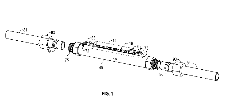
[0084] Referring now to Fig. 1, therein illustrated is a perspective view
of a water
testing apparatus for use with any cold water or hot piping 81. The piping 81
is inserted
into the coupling member 40 then a nut 93 is tightened onto the connector 75
to form a
tight seal between the water pipe 81 and the coupling member 40, allowing
water to flow
and make contact with the sensors 72. The sensors 72 transfer the signal
through the
wire 63 in the analyzer 18 and then give a reading on the LED screen 65 which
here is
powered by battery 73.
[0085] According to various exemplary embodiments, the primary opening 36
may be sized according to a size of the piping layout. The sensors 72 in which
are
inserted in the front of the coupling 40 will be in contact with the water
flowing through
36 in which will touch the sensors 72 sending a signal through the wiring 63
which is
connected to the analyzer 18 and then giving a reading on the LED screen 65.
[0086] Referring now to Fig. 2, therein illustrated is a longitudinal
partial cross-
sectional view (view along the longitudinal axis) of the apparatus for use
with any cold
water or hot water piping. Once the water pipe is connected to the coupling
member 40,
a nut is threaded onto the connection 75 (male adapter) to tighten the seal
which
prevents the water flowing through from leaking near the opening 36. The
primary
opening 36 may be sized according to a size of the piping layout. The sensors
72 in
which are inserted in the front of the coupling member 40 will be in contact
with the
water flowing through the opening 36 in which will touch the sensors 72,
sending a
signal through the wire 63 which is connected to the analyzer 18, and then
giving a
reading on the LED screen 65 (not shown in Fig. 2).
[0087] According to various exemplary embodiments, the sensors 72 can be
made of any conductive material that can receive and transmit a reading.
[0088] According to various exemplary embodiments, as shown on Fig. 1, 2
and
3, the connection 75 is a male adapter meant for compression. However, the
connection
can be made by any type of connecting means. Also the size of the coupling
member
can be any diameter.
CA 03028248 2018-12-18
WO 2017/219132 PCT/CA2017/050750
[0089] Referring now to Fig. 3, therein illustrated is transverse partial
cross-
sectional view (i.e. the cross-section view through the sensors 72) of the
water testing
apparatus to be connected to a water pipe (not shown). It is also shown that
the sensors
72 are inserted into the coupling member 40 via bores. At least a portion of
such an
apparatus will thus be in fluid flow communication with the water pipe (not
shown) and
faucet (not shown). The apparatus includes a receptacle 12 portion that holds
the
analyzer 18, the LED screen 65 and a battery compartment 73.
[0090] According to various exemplary embodiments, as shown in Fig. 1, 2
and 3
the receptacle (or encasement) 12 can be also made of any material
respectively should
be made of a none corrosive material for a reason of the condensation of the
cold water
can affect the receptacle 12.
[0091] According to various exemplary embodiments, the analyzer 18 that is
held
in the receptacle 12 can also be used to transmit a reading not only on a
visual display
screen 65 but also by Bluetooth or WIFI to a smart phone, tablet or computer.
[0092] Referring now to Fig. 4, therein illustrated is a front view of an
aerator 38
which is screwed onto a faucet by means of the female thread 41, in which the
water
flows from the portion of the aerator connected to the faucet 11 and through
the screen
39 and exiting from 68. Fig. 4 also shows a digital reading 14 (shown as
"0075") being
displayed.
[0093] Referring now to Fig. 5, therein illustrated is a front view of an
aerator 38
which is screwed onto a faucet by means of the female thread 41, in which when
the
water flows through the portion of the aerator connected to the faucet 11 and
through
the screen 39 and exiting from 68. Fig. 5 also shows a reading in code 71
(shown as
and "+++") being displayed. Such code can of course be of various colors
such as green, yellow and red to provide a user with an associated message
regarding
the quality of water. For example, "+++" or red (or any other type of visual
symbol) can
be associated to a water of poor quality or to non-potable or non-drinkable
water. For
example, "$$$" or green (or any other type of visual symbol) can be associated
to
excellent or good quality water and "***" or yellow (or any other type of
visual symbol)
can be associated with drinkable or potable water of low or medium quality.
[0094] Referring now to Fig. 6, therein illustrated is a front view of an
aerator 38
which is screwed onto a faucet by means of the female thread 41, in which when
the
water flows through the portion of the aerator connected to the faucet 11 and
through
CA 03028248 2018-12-18
WO 2017/219132 PCT/CA2017/050750
11
the screen 39 and exiting from 68. Fig. 6 also shows a visual display reading
in which
three digital forms are displayed, namely hardness of the water 88, battery
percentage
91 and water temperature 47.
[0095] Referring now to Fig. 7, therein illustrated is an exploded view of
the
aerator 38. A female thread of an upper portion of the aerator 41 is screwed
onto the
faucet. The upper portion of the aerator also has a male tread 84 so that the
body of the
aerator 38 can be screwed on with a female thread 46. The filter 39 also has a
male
thread 10 that screws into the body of the aerator 38 and in between the body
of the
aerator 38 and filter 39 there is a rubber gasket 49 to secure against leaks
and a
screen-flow director 33. Further, between the female thread of the body of the
aerator
46 and the male thread of the upper portion of the aerator 84 there is
provided a
ceramic module 69 that can be used in any material to send out readings to the
aerator
38.
[0096] According to various exemplary embodiments, referring to Figs. 4,
5, 6 and
7, all the aerators 38 work in a similar way in that the aerator 38 can be
screwed onto
any faucet of a household or building, thus giving a reading directly on the
aerator 38 or
by Bluetooth or WIFI to a smart phone, tablet or computer. Materials may also
vary
depending on the construction of the aerator 38.
[0097] Referring now to Fig. 8 and 9, therein illustrated are two
perspective views.
Fig. 8 is a perspective cross-sectional view of a two handle faucet and Fig. 9
is a
transparent perspective view of a single handle faucet. In both Fig. 8 and
Fig. 9, the
water pipe 10 runs in the center of the body of the faucet 82 (also referred
to as the
empty space of the faucet 37). Once the faucet 82 is installed and the
connectors 67
and 77 are plugged together to the receptacle 12 containing the analyzer, the
wire 63
will also run its way through the empty space of the faucet 37 until its
desired spot of the
sensors 72 that will give a reading to the display screen 14 once the water
flows through
the aerator 38 and out of the filer 39, further having a secure gasket in
place 49 to
prevent leaking. Fig. 9 shows a similar installation except that the faucet is
a single
handle faucet 92.
[0098] Referring now to Fig. 10, therein illustrated is a perspective view
of the
faucet 37 installed on a sink 1 showing that the digital screen 14 can be
installed
anywhere that is desired.
CA 03028248 2018-12-18
WO 2017/219132 PCT/CA2017/050750
12
[0099] Referring now to Fig. 11, therein illustrated is a perspective view
of the
faucet 37 being installed on a sink 1 by passing the hot water pipe 5, the
cold water pipe
8 and the wire 63 in the hole of the sink 1. Once the three parts are passed
in through
the hole of the sink 1 the hot water pipe 5 will connect to hot water valve 85
and the cold
water pipe 8 will connect to the cold water valve 98. At the end of the wire
63 there can
be a male or female adapter 67 that will fit in with the male or female
adapter of 77
leading to the analyzer 18 enclosed in the receptacle 12 to be able to send a
reading to
the LED screens 14 upon opening of the faucet by the handle 92 in which in
this figure
is a single handle.
[00100] According to various exemplary embodiments, as shown on Figs. 8, 9,
10
and 11, it will be understood that this technology can be used on any faucet
construction
or fabrication and may differ from faucet to faucet. Further, faucets may also
provide a
reading by Bluetooth or WIFI that can be emitted onto a smart phone, tablet or
computer.
[00101] The scope of the claims should not be limited by specific
embodiments
and examples provided in the disclosure, but should be given the broadest
interpretation
consistent with the disclosure as a whole.