Note: Descriptions are shown in the official language in which they were submitted.
CA 03028621 2018-12-18
Hand orthosis
The invention relates to a hand orthosis with a glove and at least one finger
splint,
wherein the finger splint can be fixed to a hand by means of the glove.
Hand orthoses of this type are already known from the prior art in numerous
embodiments, and serve to combat the progression of finger and thumb curvature
or to
prevent new curvature following surgical correction. The main application
areas are so-
called Dupuytren's contracture and finger curvature due to burn scars. ln
Dupuytren's
contracture, connective tissue nodules and strands form in the palm and
fingers between
the skin and tendons; these are benign, but lead to increasing curvature of
fingers and
thumb, accompanied by increasing inability to use the affected hand.
All of the fingers and the thumb can be affected by Dupuytren's disease. The
curvature
that develops can involve an entire finger or thumb. In rare instances,
isolated
contracture of a finger or thumb joint may occur.
Hand orthoses of the type mentioned are used to push or pull the diseased
fingers and/or
thumb that can no longer be fully extended into an extended position over a
certain time
span. Thus the hand orthoses achieve passive extension and should be worn for
several
hours at a time if possible.
For example, a hand orthosis constructed as a therapy glove is known from DE
20 2011
104 828 Ul. The glove serves for fastening an assembly designed as a fixing
splint,
consisting of a finger splint and baseplate, on a hand that is to be treated,
with the known
fixing splint made in one part. The fixing splint from DE 20 2011 104 828 Ul
is made
of sheet aluminum.
The goal of the present invention is to specify a hand orthosis in which the
pull or push
is distributed uniformly over the finger to be extended with the finger splint
and at the
same time, active countermovement of the finger is allowed.
To accomplish this goal, the invention is characterized according to the
preamble of
claim 1 in that the finger splint has at least one spring.
Here the term "finger" comprises both the regular fingers and the thumb.
Correspondingly, in the following the term "finger" is generally used, for
example in
1
CA 03028621 2018-12-18
"finger splint," which is not to bo understood as limiting. Insofar as is
appropriate, use
relating to the thumb is also meant.
The particular advantage of the invention is that a point tensile or
compressive load on
the extended finger or fingers is effectively avoided. This results in greater
wearing
comfort and thus higher acceptance of the hand orthosis according to the
invention by
the patients. As a result, the hand orthosis can be worn longer, for example.
all night.
When worn during the day it scarcely interferes with the intended use of the
finger to
be extended. In particular, active movement of the finger against the pulling
or pushing
force applied by the finger splint is possible. In this manner also stiffening
of the finger
is combated. Overall the treatment is more successful. Adverse effects, for
example,
pain, pressure ulcers or circulatory disturbances are largely avoided.
The hand orthosis according to the invention is especially suitable for
straightening
fingers affected by Dupuytren's contracture with a residual curvature of stage
1
according to Tubiana, thus of about 450 or less. For example, a residual
curvature of
this type is often present after surgery or needle fasciotomy. The causes of
the residual
curvature are primarily fibrosis strands still present or scar tissue
surrounding the
fibrosis strands, which is typically very firm. To stretch out this firm
tissue, forces in
the range of 2 N to 10 N are needed on the distal phalanx or 15 N to 50 N over
the
middle phalanx to the basal phalanx of the finger, applied for several hours
daily at the
beginning of treatment. Preferably the application of a tensile force is
performed in that
the finger splint is applied to the finger from the top and the tensile force
is distributed
over the largest possible area on the underside of the finger using a textile
which
surrounds the second and third finger joints as tautly as possible in the
transverse
direction but elastically in the longitudinal direction with air flow. The
textile is thus
part of the glove of the hand orthosis. If the finger orthosis according to
the invention
is used or applied regularly, it is sometimes possible to avoid a surgical
operation
altogether.
A particularly advantageous further development of the teaching according to
the
invention provides that the spring is provided in the form of a leaf spring,
especially as
a spring pack made of at least two stacked leaf springs. For example, the leaf
springs
of the spring pack may have the same length or different lengths. The leaf
springs of
different lengths in particular can be arranged in a cascade-like or stepped
form. As a
2
CA 03028621 2018-12-18
result, a desired distribution of the tensile or compressive force produced by
the hand
orthosis on the affected finger can be achieved with a simple design.
An advantageous further development of the above-mentioned embodiment provides
that the spring pack is designed such that the tension or compression on the
finger
extended with the finger splint decreases from the proximal to the distal end
of the
finger. In this manner also, improved mobility of the affected finger or the
finger to be
treated is achieved.
Basically the finger splint can be selected within broad limits in terms of
its type,
arrangement, sizing, shape and material. Advantageously the finger splint,
especially
the spring, in a use position of the hand orthosis extends from the entire
middle of the
hand over the base joint, the base phalanx and the middle joint at least to
the middle
phalanx of the corresponding finger. lt is especially advantageous if the
finger splint,
especially the spring, in a use position of the hand orthosis extends to the
distal phalanx
of the finger assigned to the hand orthosis. Thus essentially the entire
length of the
affected finger is included in the therapy. In this way the possible contact
surface of the
finger splint on the affected finger is maximized. Among other things, this
leads to a
lower tensile or compressive load on the individual finger areas.
In accordance with the additional further development of the invention, the at
least one
leaf spring is made of an elastically deformable, flexible steel. Particularly
preferred is
the use of spring steel or tape measure steel, as used, for example, in steel
tape measures.
For example, the steel has a thickness in the range of 0.1 mm to 0.3 mm,
preferably a
thickness of 0.15 mm to 0.25 mm and particularly preferably a thickness of
0.16 mm
or 0.2 mm. A width of the steel corresponds, for example, approximately to an
average
width of the finger to be treated. If the splinted finger is moved, and
especially curved,
the position of the curvature in the case of the steel leaf spring or leaf
springs glides
very well. In this process the spring curves above the finger without
contacting it. Thus
during active curvature of the splinted finger, unwanted friction is avoided
and the
stress on the finger is reduced. This results in high wearing comfort.
According to a further development of the invention, the spring steel -- as
usual in the
case of steel tape measures -- is arched, in other words made in a curved
shape. The
arching or cambering is preferably accomplished perpendicular to the
longitudinal
extension (lengthwise) of the spring steel or the finger splint. Particularly
preferably,
3
CA 03028621 2018-12-18
the arching of the spring steel is formed in the same way over the total
length, enabling
easy manufacturing and resulting in a high inherent positional tolerance when
applying
the finger splint.
The arched leaf springs are applied with their upper side to the top of the
finger.
Preferably all springs in a spring pack are arched in the same way. The
arching is
produced, for example, by rolling, chamfering, bending or deep drawing.
Advantageously the arching makes it possible that in case of curvature of the
finger
over the joints, a bridge forms in the spring steel, which means that even in
the case of
curvature, resting of the spring steel on the finger joint and thus
undesirable pressure
loading in this area are avoided. Furthermore, essentially the same spring
force arises
over the various curvature angles of the finger, and essentially the spring
force drops
away suddenly or immediately when a straight position for the leaf spring and
the finger
fastened to it is achieved. Furthermore, due to the arching, as a result of
the stiffening
of the material, the spring force doubles based on the material used, thus the
same
amount of material used gives a greater spring force. Therefore the finger
orthosis can
be made very slim and lightweight.
Alternatively at least one leaf spring of the spring pack is made of a plastic
and
preferably of a fiber-reinforced plastic. Fiber-reinforced plastics in
particular are light
and strong. The mechanical properties of fiber-reinforced plastics can also be
adjusted
in the desired manner by means of a plurality of parameters. For example, the
elasticity
behavior may be made directional by alignment of the fibers. The spring pack
consisting of at least two leaf springs can be produced and fastened in a
suitable way
known to the person skilled in the art.
It is advantageous if the finger splint is arranged on the outside of the hand
and thus the
assigned finger has a tensile force imposed on it. Also as a result, the
finger to be treated
as well as the affected hand as a whole undergoes less impairment of function.
A particularly simply designed realization of the embodiment according to the
invention provides that the spring is bent doubly in the area of the basal
joint of the
assigned finger and is formed in such a manner that the spring has a stiffened
or
essentially rigid middle region, from which a first elastic distal region
extends in the
direction of the palm and a second elastic distal region extends in the
direction of the
middle phalanx of the assigned finger. If greater stiffness of the middle area
of the
4
spring is necessary, a stiffening plate can additionally be arranged in the
middle area of the
spring. When a plurality of stacked leaf springs are provided, these can be
mechanically
connected in the middle region. For example, a rivet connection can be
provided to connect
the leaf springs and simultaneously form the middle region.
An alternative embodiment provides that the finger splint has a finger plate
arranged in the
area of the metacarpophalangeal joint of the assigned finger, wherein at least
one first and at
least one second spring are arranged on the finger plate, from which the first
spring extends in
the direction of the metacarpus and the second spring extends in the direction
of the middle
phalanx of the assigned finger. Thus the first spring corresponds to the first
elastic end region
and the second spring to the second elastic end region of the previous
embodiment. In this
manner the adaptation of the individual spring regions to the requirements of
the individual
case is made especially easy. For example, the first and second springs may be
made different
from one another in terms of their type, material, number and shape. The
geometry of the
finger plate can be adapted to the geometry of the hand or the degree of
finger curvature.
The finger plate can also be part of a middle module. The middle module is
then applied with
the finger plate in the area of the metacarpophalangeal joint of the assigned
finger. At the
same time, the middle module may be designed to accommodate a variable and
modifiable
number of springs, which extend in the direction of the metacarpus on one hand
and the
middle phalanx of the assigned finger on the other hand. For example,
receiving pins for the
springs may be provided on the middle module and the springs can be held in
place by a
pressure plate, retained movably with regard to the finger plate. For
removable fastening, for
example, a screw connection may be provided. Advantageously the spring force
can be
adapted through the middle module by selecting a suitable number of springs
and/or adapting
the spring geometry to the course of treatment. For example, by reducing the
springs over the
treatment period, the spring force can be reduced, or the distribution of the
spring force in the
longitudinal direction of the fingers can be modified by changing the length,
width and
thickness of the individual springs.
5
Date Recue/Date Received 2020-10-15
If an isolated contracture is formed over the distal phalanx of the finger,
the finger plate or the
rigid middle area can be applied to the middle phalanx of the finger instead
of the proximal
phalanx, or it may be applied on the middle phalanx.
According to a further development of the invention, a hand orthosis may
comprise a glove and
a finger splint, wherein the finger splint can be fixed to a hand by means of
the glove, wherein
the finger splint comprises at least one spring, wherein the finger splint,
when in a utilization
position of the hand orthosis, extends from a metacarpus of an assigned finger
of the hand, over
a metacarpophalangeal joint of the assigned finger, a proximal phalanx of the
assigned finger
and a middle joint of the assigned finger at least to a middle phalanx of the
assigned finger,
wherein the at least one spring is doubly bent in an area of the proximal
phalanx of the assigned
finger so that the at least one spring has an essentially rigid middle region,
from which a first
elastic distal area extends in a direction of the metacarpus and a second
elastic distal area
extends in a direction of the middle joint of the assigned finger.
According to a further development of the invention, a hand orthosis may
comprise a glove and
a finger splint, wherein the finger splint can be fixed to a hand by means of
the glove, wherein
the finger splint comprises at least one spring, wherein the finger splint,
when in a utilization
position of the hand orthosis, extends from a metacarpus of an assigned finger
of the hand, over
a metacarpophalangeal joint of the assigned finger, a proximal phalanx of the
assigned finger
and a middle joint of the assigned finger at least to a middle phalanx of the
assigned finger,
wherein the finger splint in an area of the proximal phalanx of the assigned
finger has a finger
plate, wherein the at least one spring comprises at least one first spring and
at least one second
spring arranged on the finger plate, wherein the at least one first spring
extends in a direction of
the metacarpus and the at least one second spring extends in a direction of
the middle phalanx of
the assigned finger.
The additional subclaims and the description that follows present additional
advantages,
features and details of the invention. Each of the features mentioned there
can be essential for
the invention, individually or in arbitrary combinations. Thus mutual
reference may be made
to the disclosures on the individual invention aspects. The drawings relate to
clarifying the
invention and do not have a limiting character.
6
Date Recue/Date Received 2020-10-15
The following are shown:
Fig. lA an exemplified embodiment of a finger splint of a hand orthosis
according to the
invention in partial view and in a side view;
Fig. 1B the exemplified embodiment of the finger splint from Fig. lA in a
partial top view;
Fig. 2 the exemplified embodiment of the finger splint from Fig. 1 in a first
utilization
position in a perspective, partial view;
Fig. 3 the exemplified embodiment of the same splint from Fig. 1 in a second
utilization
position in an additional perspective, partial view,
Fig. 4 the exemplified embodiment from Fig. 1 in a third utilization position
in a perspective
view with the glove,
Fig. 5 a perspective view of a second exemplified embodiment of the finger
splint according
to the invention with leaf springs of an arched shape,
Fig. 6 a first cross-sectional geometry of a leaf spring of the finger splint
according to
Fig. 5,
Fig. 7 an alternative, second cross-sectional geometry of a leaf spring of the
finger splint
according to Fig. 5,
Fig. 8 an alternative third cross-sectional geometry of a leaf spring of the
finger splint
according to Fig. 5,
Fig 9 an alternative, fourth cross-sectional geometry of a leaf spring of the
finger splint
according to Fig. 5 and
Fig. 10 the exemplified embodiment of the finger splint according to Fig. 5 of
the invention in
a perspective view with glove.
6a
Date Recue/Date Received 2020-10-15
CA 03028621 2018-12-18
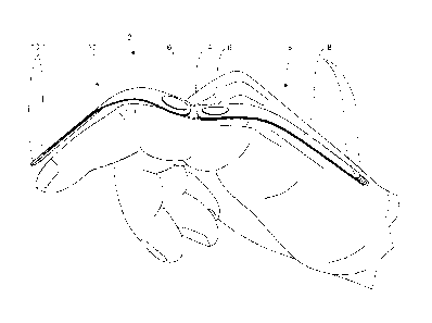
In Fig. IA an exemplified embodiment of a hand orthosis according to the
invention
with a finger splint 2 is shown in a partial view. Here the finger splint 2
has a finger
plate 4 made of aluminum, to which a first spring 8 and a second spring 10 are
fastened
over rivet connections 6. The first spring 8 and the second spring 10 are each
made of
spring packs 8, 10 from several layered leaf springs 8.1, 10.1 made of tape
measure
steel. Basically, however, the leaf springs 8.1, 10.1 can also be made of
another flexible,
elastically deformable steel, of plastic, and especially of fiber-reinforced
plastic or the
like.
The first spring pack 8 extends with its free ends, thus its elastic end
regions, in the
direction of the metacarpus and the second spring pack 10 extends with its
free ends,
thus its elastic end regions, in the direction of the middle phalanx or distal
phalanx of
the finger in question, thus the finger assigned to the hand orthosis. The
metacarpus and
the finger to be treated with the hand orthosis are shown only in Figs. 2 and
3.
Here the first spring pack 8 has six leaf springs 8.1 of equal length, while
the second
spring pack 10 has three leaf springs 10.1 located on the inside and two leaf
springs
10.1 located on the outside. The leaf springs 10.1 located on the inside are
of different
lengths relative to one another, beginning with the shortest leaf spring 10.1
on the side
of the second spring pack 10 facing the finger plate 4. The two outer leaf
springs 10.1
are of equal length and project beyond the leaf springs 10.1 on the inside. In
this manner
the leaf springs 10.1 on the inside are encompassed by leaf springs 10.1
located on the
outside, which facilitates fixation in the glove, not shown in Fig. IA, and
thus on the
affected hand and the finger to be treated.
The finger splint 2 with the finger plate 4 and the two spring packs 8, 10 is
designed
such that the assigned finger is subjected to tensile strength by the hand
orthosis in its
utilization position, wherein the tension on the finger extended with the
finger splint 2
decreases from the proximal to the distal end of the finger. For this purpose
also see the
positions of the hand orthosis in use shown in Figs. 2 and 3.
Thus the finger splint 2 is located on the exterior of the affected hand. In
this way the
function of the hand and fingers, not only of the finger to be treated, are
less impaired
than if the finger splint were arranged on the inside of the hand. This is
especially true
if several fingers are to be treated and thus several finger splints must be
used
simultaneously.
7
CA 03028621 2018-12-18
Fig. 1B shows the exemplified embodiment from Fig. IA in a partial top view,
thus --
relative to the plane of the paper -- with a viewing direction from the top in
Fig. 1A.
Fig. 2 shows the hand orthosis from Fig. 1A and Fig. 1B in a first utilization
position
on an affected hand. The hand orthosis is shown in Fig. 2 without the glove to
improve
the visibility. The hand orthosis is applied on the affected finger, here the
little finger
and is fixed by the glove not only to the finger pad of the small finger and
the
metacarpus. Instead the finger splint 2 is in contact via the glove over a
broad area with
the finger being treated and thus is in force transfer connection with the
affected finger.
The advantage of this is that the tensile loading on the little finger is
distributed
essentially over the entire finger or the distal phalanx and the middle
phalanx. At the
same time, the load on the individual finger regions is correspondingly low.
The little
finger is shown in a curved position in the first utilization situation.
The finger splint 2 is arranged on a glove 12 shown only in Fig. 4 and is
fixed to the
hand to be treated and positioned by means of the glove 12. For example, the
finger
splint can be fastened to the glove by means of fastening pockets 12.1, 12.2
and strip
12.3. The finger splint 2 can even be an integral part of the glove 12. The
glove 12 in
the present exemplified embodiment, for better positioning of the finger
splint 2 has a
first fastening pocket 12.1 assigned to the finger to be treated and designed
as an
insertion pocket and a second fastening pocket 12.2 provided over the back of
the hand.
A fastening strap 12.3 provided in the area of the finger plate 4 is shown in
this Fig. as
a hook and loop fastener. Using the fastening strap 12.3 the hand orthosis can
be
attached in a particularly simple way, even by the patient.
As is clearly recognizable from Fig. 2, the finger splint 2 in a curved
position of the
finger with the finger plate 4 is adjacent to the proximal phalanx of the
little finger. The
positioning need not be done directly, but indirectly, for example if the
finger splint 2
as shown in the existing embodiment according to Fig. 4 in this area is
inserted into a
fastening pocket or strap 12.1, 12.2, 12.3 of the glove 12. The first spring
pack 8,
starting from the finger plate 4, extends in the direction of the metacarpus.
In this case
the size of the attachment of the first spring pack 8 to the metacarpus
determines the
tensile force acting on the splinted finger. Then the second spring pack 10 in
the usage
position of the hand orthosis, starting from the finger plate 4, extends to
the middle
phalanx or distal phalanx of the little finger. As long as the finger is
extended, the finger
8
CA 03028621 2018-12-18
plate 4 must not contact the proximal phalanx. It is preferably kept at a
distance from
the finger by the spring 8 and somewhat floats over the proximal phalanx with
the
consequence that pressure is reduced and the comfort of wearing is promoted.
The little finger is placed under tensile stress by the hand orthosis. For
this reason the
two spring packs 8, 10 are supported against the finger plate 4 lying against
the
proximal phalanx. The finger plate 4 is correspondingly curved in the finger
extension
direction; also see Fig. 1A. Thus depending on the degree of curvature of the
finger
plate 4, the tensile force applied to the assigned finger can be adjusted or
predetermined.
The degree of bending of the finger plate 4 is an additional parameter for
achieving the
desired tensile load.
It is also apparent from Fig. 2 that the finger splint 2 of the hand orthosis
in the first
utilization position of the hand orthosis shown here extends from the
metacarpus, over
the metacarpophalangeal joint, the proximal phalanx, the middle joint, the
middle
phalanx and the distal joint to the pad of the little finger. It is also
recognizable that the
first spring pack 8 here is essentially positioned one-third in the area of
the proximal
phalanx of the little finger and two-thirds in the area of the metacarpus.
Fig. 3 shows the exemplified embodiment in a second utilization position. In
contrast
to Fig. 2, the index
finger is shown here as the finger to be treated. The purpose of
this is only to make clear the flexible application of the otherwise identical
basic design.
In Fig. 3 the linger to be treated shown in extended position; compare Fig. 2.
Here also
for the sake of visibility the hand orthosis is shown without the glove 12.
In Fig. 4 the complete hand orthosis of the present exemplified embodiment is
illustrated in a utilization position analogous to Fig. 3. As was already
stated regarding
Fig. 3, it makes no difference for the explanation of the exemplified
embodiment
whether the finger to be treated is the little finger according to Fig. 2 or
the index finger
according to Figs. 3 and 4. The basic structure of the hand orthosis according
to the
present exemplified embodiment is identical.
The fastening pocket 12.1 in the area of the middle phalanx and the distal
phalanx of
the finger being treated, into which the spring pack 10 is inserted is clearly
recognizable,
along with the fastening strap 12.3 in the area of the proximal phalanx of the
index
finger illustrated as a hook and loop closure, through which the finger plate
4, not shown
9
in Fig. 4, can be easily fixed movably, and the fastening pocket 12.2,
illustrated as an insertion
pocket, into which the spring pack 8 is inserted with its free end.
An alternative embodiment of the finger splint 2 according to Fig. 5, as
usual, a first spring
pack 8 and a second spring pack 10, which as shown here are connected by a
middle module
14 having the finger plate 4. The spring packs 8, 10 here are removably
attached to the middle
module 14. For this purpose the middle module 14 has a plurality of pins 14.1,
which serve to
fasten the leaf springs 8.1, 10.1 of the spring packs 8, 10. Thus
corresponding to the pins 14.1
of the middle module 14, recesses 8.2, 10.2 are formed on the leaf springs
8.1, 10.1. In
addition the middle module 14 provides a pressure plate 14.2, which is
removably connected
over a screw 14.3 with the finger plate 4. Between the finger plate 4 and
pressure plate 14.2
here the leaf springs 8.1, 10.1 of the spring packs 8, 10 are fastened.
The provision of the middle module 14 with the removably attached pressure
plate 14.2 makes
it possible to select the number of leaf springs 8.1, 10.1 and the geometry
thereof to be
variable and, especially, to adjust them to the progress of treatment as the
treatment continues.
At the same time the finger plate 4, which is positioned in the area of the
proximal phalanx to
the finger from the top guarantees that the comfort of wearing is maintained
or at least not
affected negatively.
For example, it is shown in Fig. 5 that the leaf springs 8.1, 10.1 are arched.
The arched shape
is realized such that finger splint 2 is positioned with its hollow side from
above on the
splinted finger and on the back of the hand. As a result of the arched shape
the finger can be
bent, wherein even with a curvature over a joint of the finger, the spring
pack 8, 10 forms a
bridge and is provided at a distance from the joint. Preferably the bridge is
always formed
exactly in the center above the joint. In particular the bridge formation
avoids mechanical
contact and prevents uncomfortable pressure loading. As a result, the wearing
comfort of the
finger splint according to the invention is increased.
Alternative embodiments of the arching are shown as examples in Figs. 6 - 9.
Figs. 6-9 show
an individual leaf spring 8.1 as an example in cross-section, i.e., transfers
to the lengthwise
extension of the leaf spring 8.1. It is preferably provided that all leaf
springs 8.1, 10.1 of the
spring packs 8, 10 are arched in the same way and thus can be placed directly
one on top of
the other in a laminar pattern.
Date Recue/Date Received 2020-10-15
CA 03028621 2018-12-18
The finger splint 2 according to Fig. 5 is inserted in a glove 12 in Fig. 10.
For this
purpose the first spring pack 8 and the second spring pack 10 are inserted
into the
fastening pockets 12.1, 12.2 of the glove 12. The positioning of the finger
splint 2 on
the hand is accomplished in that the middle module the center module 14 is
provided
with the finger plate 4 over the proximal phalanx of the splinted finger. The
spring
packs 8, 10 with the springs 8.1, 10.1 having an arched design are placed on
the fingers
and the back of the hand with the hollow side at the top.
The fixation of the finger splint 2 to the glove 12 and/or the hand in the
present case is
accomplished first by way of a retaining strap 12.4, which is guided from the
first
fastening pocket 12.1 receiving the second packet 10 in the direction of the
second
fastening pocket 12.2, a flexible strap 12.5 following the retaining strap
12.4, and a
hook and loop strap 12.6, which is connected to the flexible strap 12.5 and is
fastened
movably to the second fastening pocket 12.2. The surface of the fastening
pocket 12.2
and the hook and loop strap 12.6 thus form the two sides of a hook and loop
connection.
Furthermore the fastening is achieved with a lashing strap 12.7, which in the
position
of use is guided over the back of the hand and presses the first spring pack 8
against the
back of the hand. Preferably a spring element is inserted in the lashing strap
12.7, which
exerts a variable force on the first spring pack 8, simultaneously increasing
the comfort
of wearing and promoting secure attachment.
The invention is not limited to the exemplified embodiment explained on the
basis of
Figs. 1-10.
Although the present exemplified embodiment relates to the use of the hand
orthosis
according to the invention on a human hand, use on an animal's paw would also
be
conceivable.
In individual cases it may be advantageous to place at least one finger splint
of the hand
orthosis according to the invention on the inside of the hand in the position
of use.
Correspondingly, pressure would be applied to the damaged finger or fingers by
a hand
orthosis of this type. It is also possible for finger splints to be placed on
both the inside
and the outside of the hand.
Then, finger splints of this type can he applied to different fingers or to a
single finger
to be treated.
11
CA 03028621 2018-12-18
The person skilled in the art, depending on the specific application, will
select the
required number of leaf springs and the length thereof for each individual
finger to be
treated. Correspondingly the number of leaf springs need not necessarily be
identical
for each spring pack or each finger splint.
Positioning of the spring packs 8, 10 at a shallow angle relative to one
another can be
achieved as in the exemplified embodiment according to Fig. 1A in that the
finger plate
4 is designed with a curve. For example, the position can be achieved using
wedge
inserts provided between the spring packs 8, 10 and the finger plate 4. The
wedge inserts
can thus also be used in the case of the center module 14.
By means of the glove to which the at least one finger splint of the hand
orthosis is
fastened or in which it is integrated, both could transfer a force from the
hand orthosis
to the diseased finger on the hand and good comfort in wearing can be
achieved.
Correspondingly the design of the hand orthosis according to the invention is
very
simple and thus cost-advantageous. Through the suitable attachment of
fastening straps
and pockets the at least one finger splint can be positioned reliably relative
to the
assigned finger, thus the finger to be treated.
In the exemplified embodiment explained, the glove is designed as a full glove
except
for the finger tips. Basically, however, it is possible for only the one or
more fingers to
be treated or gloved, or that the fingers that are not affected are only
partially
surrounded by the glove. This can be the case over the entire finger length
and over
only a partial length of the finger.
It is also possible to design the glove as a universal glove which provides
fastening
elements, for example, fastening straps and pockets or the like, for receiving
a finger
splint or several finger splints for a plurality of fingers. The glove of the
exemplified
embodiment has the fastening elements for the finger splint on the outside of
the hand.
In other applications, however, the fastening elements could also be
positioned on the
hand inside of the glove or the hand inside and the hand outside of the glove.
With the hand orthosis of the invention, the tensile or pressure application
applied On
the finger to be treated is distributed more uniformly thereon. In addition
more reliable
positioning of the finger splint is facilitated.
CA 03028621 2018-12-18
Instead of the rivet connections 6 fixed between the finger plate 4 and the
first and
second spring packs 8, 10, other connecting technologies known to the person
skilled
in the art and suitable for this purpose are possible.
The finger splint of the hand orthosis need not necessarily extend to the
finger pad of
the affected finger. However, extension to the distal phalanx of the assigned
finger is
advantageous, since in this way the load on the finger is distributed even
better by the
hand orthosis and a better lever effect is achieved.
The arched design of the leaf springs 8.1, 10.1 is shown as an example for the
exemplified embodiment according to Fig. 5. According to the invention the
arched
design of the leaf springs 8.1, 10.1 can also be used for the finger splints
according to
Figs. 1-4 and any other finger splints. The arching is thus also not limited
to the use of
the center module 14. In particular the arching can be used in the design of
the finger
plate 4 and/or together with a rivet connection 6 for the spring packs 8, 10.
The at least one spring of the finger splint need not have the design
according to the
exemplified embodiment. For example, it is conceivable that only a single
spring or a
single spring pack consisting of multiple layered leaf spring is used. Thus
the finger
splints could also consist of a single spring or a single spring pack. In
analogy to the
finger splint of the exemplified embodiment, this spring or this spring pack,
in a
utilization position of the hand orthosis, can extend from the metacarpus,
over the
metacarpophalangeal joint, the proximal phalanx and the middle joint at least
to the
middle phalanx, preferably to the distal phalanx, of the assigned finger.
In an initial phase of the therapy, for example, six to 25 springs are
combined to form
a pack to supply the necessary force. In a later phase of therapy then the
spring force,
for example, of a single spring may be adequate to achieve residual full
straightening
of the finger being treated or, for example, to maintain straightening
achieved following
surgery.
Alternatively to the exemplified embodiment explained based on Figs. 1-10, the
single
spring or the single spring pack can be designed to be doubly bent in the area
of the
proximal phalanx of the assigned finger in such a manner that the spring or
the spring
pack has an essentially rigid middle region, from which a first elastic
terminal region
extends in the direction of the metacarpus and the second elastic terminal
region extends
in the direction of the middle phalanx of the assigned finger.
13
CA 03028621 2018-12-18
Thus in the case of one spring pack, the individual leaf springs of the spring
pack in the
first case would simply be placed on inside of the other. Due to the special
design of
each leaf spring with the two bending sites and the middle region formed in
this way,
the individual leaf springs slid into the treatment glove as a spring pack
would
automatically maintain their position in the spring pack even when the hand
orthosis
was in use. However it would also be conceivable that the individual leaf
springs of the
spring pack would be fixed together by fastening means such as rivets or the
like. For
example, a rivet connection could be provided at each end of the middle region
formed
by the bending points.
This middle region would then take over the function of the finger plate 4 of
the
exemplified embodiment. To increase the stiffness of the middle region formed
in this
way it would be conceivable to supply a stiffening plate in the middle region
of the
splint. This stiffening plate, for example, in analogy to the exemplified
embodiment
could be fastened with two rivet connections to the spring or the spring pack.
Another alternative embodiment provides that the finger splint is fastened
through a
baseplate, wherein the baseplate is fixable by the glove in the area of the
metacarpus
and the finger splints, especially the springs, in the use position of the
hand orthosis
extends from the base plate, over the proximal joint, the proximal phalanx and
the
middle joint at least to the middle phalanx, especially to the distal phalanx,
of the
assigned finger. Thus in this embodiment only one free end of the spring or
the spring
pack and thus only one elastic end would be formed.
In contrast to known hand orthoses, the hand orthosis according to the
invention can be
better adapted for use in a later stage of therapy, thus when the fingers are
extended
fairly far. The hand orthosis according to the invention has a lower weight,
causes less
limitation of the freedom of motion of the affected hand and the affected
finger, and
thus offers higher comfort in wearing.
In addition to the materials mentioned for the finger plate and the leaf
springs, other
materials known to the expert and suitable for use are conceivable. A
combination of
materials differing from one another for the finger plate, the leaf springs,
the spring
packs and other components of the hand orthosis according to the invention are
possible.
Optionally according to the invention it can be provided that a silicone
cushion is
present on the finger splint 2 on a side facing the finger and/or the back of
the hand in
CA 03028621 2018-12-18
its utilization position, at least in one section. The silicone cushion can
provide a soft
contact surface and contribute to improve the wearing comfort.
CA 03028621 2018-12-18
List of symbols
2 Finger splint
4 Finger plate
6 Rivet connector
8 First spring, formed as the first spring pack made of multiple leaf
springs
8.1 Leaf springs of the first spring pack
8.2 Recess
Second spring, formed as the second spring pack made of multiple leaf springs
10.1 Leaf springs of the second spring pack
10.2 Recess
12 Glove
12.1 Fastening pocket, formed as insertion pocket
12.2 Fastening pocket, formed as insertion pocket
12.3 Fastening strip, formed as a hook-and-loop strap
12.4 Retaining strap
12.5 Hook-and-loop strap
12.7 Lashing strap with inserted spring element
14 Middle module
14.1 Pin
14.2 Pressure plate
14.3 Screw
16