Note: Descriptions are shown in the official language in which they were submitted.
ELECTRIC WATER PUMP
BACKGROUND OF THE INVENTION
Field of the Invention
The present disclosure relates to an electric water pump and, more
particularly, to a
heat dissipation structure of an electric water pump.
Description of the Related Art
With the improvement of people's living standard, there are an increasing
number of
outdoor leisure facilities such as swimming pools. Accordingly, there is a
growing demand for
electric water pumps, which serve as commonly-used ancillary facilities of the
swimming
pools. For existing electric water pumps, motor housings of drive motors also
serve as casings
of the electric water pumps, and thus the drive motors have defects such as
poor heat
dissipation effect and short service life, etc.
BRIEF SUMMARY OF THE INVENTION
To solve deficiencies of the prior art, the present disclosure provides an
electric water
pump having a high heat dissipation efficiency.
To achieve the above objective, the present disclosure adopts the following
technical
solutions.
According to an aspect of the invention, there is provided an electric water
pump,
comprising: a drive motor for driving the electric water pump, wherein the
drive motor
comprises a cylinder-shaped motor housing, a stator arranged on an inner wall
of the motor
housing, a rotor rotatably arranged in the stator, a motor shaft connected
into the rotor and
rotating with the rotor, and an end cover; the motor housing is fixedly
mounted on a side of the
end cover, the motor housing and the end cover are provided with a bearing for
supporting the
motor shaft, and the motor shaft rotates with respect to the bearing; a side
of the end cover is
fixedly provided with a cylinder-shaped casing, the motor housing is
positioned in the casing,
and a central axis line of the motor housing coincides with a central axis
line of the casing;
another side of the end cover is provided with a pump body having a chamber,
the pump body
is internally provided with a rotating blade, and the rotating blade is
connected to the motor
1
Date Recue/Date Received 2020-11-06
shaft and is driven by the motor shaft to rotate; the pump body is provided
with a water inlet
and a water outlet communicating with the chamber; an end of the motor shaft
away from the
end cover is fixedly provided with a heat-dissipating fan; an end of the
casing close to the end
cover is provided with a first air inlet; a rear end of the casing away from
the end cover is
provided with a first air outlet; and the first air inlet, a gap between the
motor housing and the
casing and the first air outlet form a first heat dissipation path;.
wherein an outside surface of the casing is provided with a control box; the
control box
is internally provided with a controller electrically connected to the drive
motor to control the
drive motor to work; a plurality of heat dissipation fins are formed on an
outside surface of the
control box, and the plurality of heat dissipation fins are positioned between
the control box
and the drive motor and extend along an axial direction of the motor shaft; a
location of the
casing opposite to the plurality of heat dissipation fins is provided with an
plug window for
inserting the plurality of heat dissipation fins; and the first heat
dissipation path passes through
the plurality of heat dissipation fins;
wherein a second air inlet is formed on a surface of the control box diverging
from the
casing; a second air outlet is formed between the plurality of heat
dissipation fins; and the
second air inlet, an inner chamber of the control box, the second air outlet,
the plug window,
the gap between the motor housing and the casing, and the first air outlet
form a second heat
dissipation path, and the second heat dissipation path passes through the
plurality of heat
dissipation fins.
An electric water pump includes a drive motor for driving the electric water
pump. The
drive motor includes a cylinder-shaped motor housing, a stator arranged on an
inner wall of the
motor housing, a rotor rotatablely arranged in the stator, a motor shaft
connected into the rotor
and rotating with the rotor, and an end cover. The motor housing is fixedly
mounted on a side
of the end cover, the motor housing and the end cover are provided with a
bearing for
supporting the motor shaft, and the motor shaft rotates with respect to the
bearing. A side of
the end cover is fixedly provided with a cylinder-shaped casing, the motor
housing is
positioned in the casing, and a central axis line of the motor housing
coincides with a central
axis line of the casing. Another side of the end cover is provided with a pump
body having a
chamber, the pump body is
la
Date Recue/Date Received 2020-11-06
internally provided with a rotating blade, and the rotating blade is connected
to the motor shaft
and is driven by the motor shaft to rotate. The pump body is provided with a
water inlet and a
water outlet communicating with the chamber. An end of the motor shaft away
from the end
cover is fixedly provided with a heat-dissipating fan, an end of the casing
close to the end cover
is provided with a first air inlet, and a rear end away from the casing is
provided with a first air
outlet. The first air inlet, a gap between the motor housing and the casing
and the first air outlet
form a first heat dissipation path.
Further, a range of a ratio of an outer diameter of the motor housing to an
inner diameter of the
casing may be greater than or equal to 0.75 and smaller than or equal to 0.95.
Further, a range of the gap between the motor housing and the casing may be
greater than or
equal to 5 mm.
Further, an outside surface of the casing may be provided with a control box.
The control box
may be internally provided with a controller electrically connected to the
drive motor to control
the drive motor to work. A plurality of heat dissipation fins may be formed on
an outside surface
of the control box, and the plurality of heat dissipation fins may be
positioned between the
control box and the drive motor and extend along an axial direction of the
motor shaft. A location
of the casing opposite to the heat dissipation fin may be provided with an
plug window for
inserting the heat dissipation fin. The first heat dissipation path may pass
through the heat
dissipation fin.
Further, a first face passing through a center of rotation of the motor shaft
may be tangent to one
of the heat dissipation fins, and the plurality of heat dissipation fins may
be positioned on the
same side of the first face. A second face passing through the center of
rotation of the motor shaft
may be tangent to another one of the heat dissipation fins, and the plurality
of heat dissipation
fins may be positioned on the same side of the second face. A range of an
included angle formed
by the first face and the second face intersecting with one another may be
greater than or equal to
300 and smaller than or equal to 80 .
Further, the first face and the second face may divide space into four
regions, and the first air
inlet and the heat dissipation fin may be positioned within the same region.
Further, a distance from a center of rotation of the motor shaft to an end of
each of the heat
dissipation fins away from the controller may be equal.
Further, a second air inlet may be formed on a surface of the controller
diverging from the
2
CA 3028723 2018-12-31
casing, and a second air outlet may be formed between the plurality of heat
dissipation fins. The
second air inlet, an inner chamber of the controller, the second air outlet,
the plug window, the
gap between the motor housing and the casing, and the first air outlet may
form a second heat
dissipation path, and the second heat dissipation path may pass through the
heat dissipation fins.
Further, the second air inlet may be positioned at an end of the controller
close to the end cover.
Further, the casing may be also internally provided with a air guiding cover
for guiding air flow,
and the air guiding cover may be positioned between the fan and the drive
motor.
Beneficial effects of the present disclosure are as below: the first heat
dissipation path formed by
the first air inlet, the gap between the motor housing and the casing and the
first air outlet may
provide a heat dissipation effect for the electric water pump.
The beneficial effects of the present disclosure also lie in that the heat
dissipation efficiency of
the controller is enhanced by embedding the heat dissipation fin on the
controller into the first
heat dissipation path.
BRIEF DESCRIPTION OF THE DRAWINGS
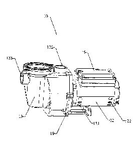
FIG 1 is a schematic diagram of an electric water pump according to the
present disclosure;
FIG 2 is a cross-sectional view of the electric water pump in FIG 1; and
FIG. 3 is a cross-sectional view of the electric water pump in FIG 1 from
another viewing angle;
Numerals: 10-electric water pump, 11-drive motor, 111-motor housing, 112-
stator, 113-rotor,
114-motor shaft, 115-end cover, 12-casing, 13-pump body, 131-rotating
impeller, 132-water
inlet, 133-water outlet, 14-heat-dissipating fan, 121-first air inlet, 122-
first air outlet, first heat
dissipation path, 15-control box, 151-heat dissipation fin, 123-plug window,
16-first face,
17-second face, 124-air guiding cover, 18-pad, and 19-support frame.
DETAILED DESCRIPTION OF THE INVENTION
The present disclosure is introduced in detail below with reference to the
accompanying
drawings and embodiments.
As shown in FIG 1 to FIG 3, an electric water pump 10 includes a drive motor
11 for driving the
electric water pump 10. The drive motor 11 includes a motor housing 111, a
stator 112, a rotor
113, a motor shaft 114, and an end cover 115.
3
CA 3028723 2018-12-31
Specifically, the motor housing 111 is cylinder-shaped, the stator 112 is
arranged on an inner
wall of the cylinder-shaped motor housing 111, the rotor 113 is rotatablely
arranged in the stator
112, and the motor shaft 114 is inserted into the rotor 113 and rotates with
the rotor 113.
The motor housing 111 is fixedly mounted on a side of the end cover 115. The
motor housing
111 and the end cover 115 are provided with a bearing for supporting the motor
shaft 114. The
motor shaft 114 is rotatablely mounted on the bearing. A casing 12 wraps the
motor housing 111
up, and the casing 12 is fixed to the end cover 115. A central axis line of
the motor housing 111
coincides with a central axis line of the casing 12.
A pump body 13 having a chamber is mounted on another side of the end cover
115. The pump
body 13 is internally provided with a rotating impeller 131, and the rotating
impeller 131 is
connected to the motor shaft 114 and is driven by the motor shaft 114 to
rotate. The pump body
13 is provided with a water inlet 132 and a water outlet 133 communicating
with the chamber,
wherein the water inlet 132 and the water outlet 133 are respectively used for
sucking water and
discharging water. An end of the motor shaft 114 away from the end cover 115
is fixedly
provided with a heat-dissipating fan 14, an end of the casing 12 close to the
end cover 115 is
provided with a first air inlet 121, and a rear end away from the casing 12 is
provided with a first
air outlet 122. The first air inlet 121, a gap between the motor housing 111
and the casing 12 and
the first air outlet 122 form a first heat dissipation path. When the heat-
dissipating fan 14 is
driven to rotate, air flow enters the casing 12 through the first air inlet
121, then passes through
the heat-dissipating fan 14 via the gap between the motor housing 111 and the
casing 12, and
finally is discharged from the casing 12 via the first air outlet 122. In this
way, the air flow flows
through the outer surface of the motor housing 111 to dissipate heat for the
drive motor 11.
Specifically, the electric water pump 10 is also provided with a support frame
19 used for
supporting the electric water pump 10.
As a preferred embodiment, a range of a ratio of an outer diameter of the
motor housing 111 to
an inner diameter of the casing 12 is greater than or equal to 0.75 and
smaller than or equal to
0.95.
Specifically, parameter settings of the outer diameter of the motor housing
111 and the inner
diameter of the casing 12 are related to air flow ventilation quantity of the
first heat dissipation
path and the overall dimension of the electric water pump 10. The ventilation
quantity of the first
heat dissipation path is ensured under the premise of guaranteeing the overall
compact structure
and smaller overall size, such that the electric water pump 10 is maintained
at a higher heat
4
CA 3028723 2018-12-31
dissipation level. Generally, the range of the ratio of the outer diameter of
the motor housing 111
to the inner diameter of the casing 12 is greater than or equal to 0.75 and
smaller than or equal to
0.95. In this embodiment, the outer diameter of the motor housing 111 is 72
mm, the inner
diameter of the casing 12 is 80 mm, and thus the ratio of the outer diameter
of the motor housing
111 to the inner diameter of the casing 12 is 0.9.
As a preferred embodiment, a range of the gap between the motor housing 111
and the casing 12
is greater than or equal to 5 mm. To ensure the ventilation quantity of the
first heat dissipation
path, the range of the gap between the motor housing 1 1 1 and the casing 12
is controlled to be
greater than or equal to 5 mm. In this embodiment, the gap between the motor
housing 111 and
the casing 12 is 8 mm.
As a preferred embodiment, an outside surface of the casing 12 is provided
with a control box
15. The control box 15 is internally provided with a controller (not shown)
electrically connected
to the drive motor 11 to control the drive motor 11 to work. A plurality of
heat dissipation fins
151 are formed on an outside surface of the control box 15, and the plurality
of heat dissipation
fins 151 are positioned between the control box 15 and the drive motor 11 and
extend along an
axial direction of the motor shaft 114. A location of the casing 12 opposite
to the heat dissipation
fin 151 is provided with an plug window 123 for inserting the heat dissipation
fin 151. The first
heat dissipation path passes through the heat dissipation fin 151.
Specifically, the control box 15 is made of metal (generally aluminum). A
plurality of heat
dissipation fins 151 are integrally-molded on the control box 15, wherein the
heat dissipation fins
151 extend along an axial direction of the motor shaft 114. The casing 12 is
provided with an
plug window 123. When the control box 15 is mounted on the casing 12, the heat
dissipation fins
151 are inserted into the casing 12 and are positioned in the first heat
dissipation path. When the
heat-dissipating fan 14 is driven to rotate, air flow enters the casing 12
through the first air inlet
121, then passes through the heat-dissipating fan 14 via the gap between the
motor housing 111
and the casing 12, and finally is discharged from the casing 12 via the first
air outlet 122. In this
way, the air flow flows through the heat dissipation fins 151 to dissipate
heat for the control box
15. The control box 15 is fixedly mounted on the casing 12, and a pad 18 may
be arranged
between the control box 15 and the casing 12.
As a preferred embodiment, a first face 16 passing through a center of
rotation of the motor shaft
114 is tangent to one of the heat dissipation fins 151, and the plurality of
heat dissipation fins
151 are positioned on the same side of the first face 16. A second face 17
passing through the
CA 3028723 2018-12-31
center of rotation of the motor shaft 114 is tangent to another one of the
heat dissipation fins 151,
and the plurality of heat dissipation fins 151 are positioned on the same side
of the second face
17. A range of an included angle formed by the first face 16 and the second
face 17 intersecting
with one another is greater than or equal to 300 and smaller than or equal to
80 .
Specifically, the dimension of the heat dissipation fin 151 is restricted by
many conditions. When
the dimension of the heat dissipation fin 151 is too small, the heat
dissipation fin 151 has a lower
heat dissipation effect on the control box 15. If the dimension of the heat
dissipation fin 151 is
too large, this may have a negative effect on the overall structure design and
component
arrangement. Therefore, to ensure the heat dissipation efficiency of the
control box 15 and the
overall structure design, two planes passing through the center of rotation of
the motor shaft 114
are employed to limit the dimension of the heat dissipation fin 151, wherein
the first plane 16 is
tangent to one heat dissipation fin 151 outside, and the second plane 17 is
tangent to another heat
dissipation fin 151 outside. All the heat dissipation fins 151 are positioned
within a region
restricted by the first plane 16 and the second plane 17. The range of the
included angle between
the first plane 16 and the second plane 17 is greater than or equal to 300 and
smaller than or
equal to 80 . In this embodiment, the included angle between the first plane
16 and the second
plane 17 is 570.
As a preferred embodiment, a range of a ratio of the included angle between
the first face 16 and
the second face 17 to the radius of the heat-dissipating fan 14 is greater
than or equal to 0.8 /mm
and smaller than or equal to 1.5 /mm.
Specifically, the heat-dissipating fan 14 needs to dissipate heat for the heat
dissipation fin 151.
The dimension of the heat-dissipating fan 14 depends on the size of the heat
dissipation fin 151.
When the heat dissipation fin 151 has a larger dimension, the heat-dissipating
fan 14 having a
larger dimension is required to dissipate heat for the heat dissipation fin
151. In this embodiment,
the radius of the heat-dissipating fan 14 is 60 mm, and the ratio of the
included angle between
the first face 16 and the second face 17 to the radius of the heat-dissipating
fan 14 is 0.95 km.
As an alternative embodiment, the first face 16 and the second face 17 divide
space into four
regions. The first air inlet 121 and the heat dissipation fin 151 are
positioned within the same
region.
Specifically, quantities of air flow are different at different locations of
the first heat dissipation
path. The first face 16 and the second face 17 divide space into four regions,
and the first air inlet
121 and the heat dissipation fin 151 are positioned within the same region.
Air flow entering the
6
CA 3028723 2018-12-31
casing via the first air inlet 121 flows through the heat dissipation fin 151
in priority to enhance
the heat dissipation effect of the heat dissipation fin 151 on the control box
15.
As a preferred embodiment, a distance from a center of rotation of the motor
shaft 114 to an end
of each of the heat dissipation fins 151 away from the control box 15 is
equal.
Specifically, ends of all the heat dissipation fins 151 away from the control
box 15 are positioned
on a circle concentric with respect to the motor housing 111, such that the
heat dissipation fins
151 may more closely mate with the motor housing 111.
As a preferred embodiment, a second air inlet is formed on a surface of the
control box 15
diverging from the casing 12. A second air outlet is formed between the
plurality of heat
dissipation fins 151. The second air inlet, an inner chamber of the control
box 15, the second air
outlet, the plug window 123, the gap between the motor housing 111 and the
casing 12, and the
first air outlet 122 form a second heat dissipation path, and the second heat
dissipation path
passes through the heat dissipation fins 151.
Specifically, the second air inlet is formed on the surface of the control box
15 diverging from
the casing 12. The second air outlet is formed between the plurality of heat
dissipation fins 151.
When the heat-dissipating fan 14 is driven to rotate, air flow enters the
inner chamber of the
control box 15 through the second air inlet, then enters the casing 12 via the
second air outlet,
then passes through the heat-dissipating fan 14 via the gap between the motor
housing 111 and
the casing 12, and finally is discharged from the casing 12 via the first air
outlet 122.
As a preferred embodiment, the second air inlet 152 is positioned at an end of
the control box 15
close to the end cover 115. Specifically, the second air inlet 152 is arranged
away from the first
air outlet 122, such that hot air flow discharged from the first air outlet
122 is prevented from
directly entering the second air inlet 152, which may cause the hot air flow
to circulate between
the second air inlet 152 and the first air outlet 122.
As a preferred embodiment, the casing 12 is further internally provided with a
air guiding cover
124 for guiding air flow, and the air guiding cover 124 is positioned between
the fan and the
drive motor 11. Specifically, the air guiding cover 124 guides the air flow to
the heat-dissipating
fan 14, thereby preventing the air flow from flowing at random and enhancing
the heat
dissipation efficiency.
The above shows and describes fundamental principles, major characteristics
and advantages of
the present disclosure. Those skilled in the art should understand that the
above embodiments are
7
CA 3028723 2018-12-31
not intended to limit the present disclosure in any form, and any technical
solution obtained
based on equivalent replacements or equivalent transformations fall within the
scope of
protection of the present disclosure.
8
CA 3028723 2018-12-31