Note: Descriptions are shown in the official language in which they were submitted.
CA 03028860 2018-12-19
DESCRIPTION
[Title of Invention] METHOD FOR ESTIMATING THE POSITION AND SPEED OF THE
ROTOR OF AN ALTERNATING CURRENT MACHINE FOR A MOTOR VEHICLE, AND
CORRESPONDING SYSTEM
[Technical Field]
[0001]
The technical field of the invention is the control of electric machines for a
motor
vehicle, and more particularly the estimation of quantities involved in such
controls.
[Background Art]
[0002]
The sophisticated control strategies for electric machines require a precise
knowledge
of the position and/or of the speed of the rotor. These mechanical quantities
are traditionally
measured.
[0003]
With such a control structure, the dynamic performance levels of the
alternating
current machines are better than those of the direct current machines. On the
other hand,
powerful digital computers, power components with high switching frequencies
and some
additional sensors connected to the engine shaft linked to the rotor are
required for such
sophisticated control.
[0004]
The use of mechanical sensors, for measuring the position and/or the speed of
the rotor,
in a control structure of the electric machines creates a number of
constraints, among which it
is possible to cite the additional costs of the sensors and of their
associated electronics, the bulk
due to the installation of the sensors and the wiring thereof, the sensitivity
of the sensors to
their environment (temperature, noise, mechanical oscillations,
electromagnetic compatibility,
etc.) and the possibility of failure of a sensor or of one of its connections,
which reduces the
reliability of the system.
[0005]
These constraints limit the use of the sensors, even make it impossible, in
some
applications. For that, there is an effort to replace the mechanical sensors
which measure the
1
CA 03028860 2018-12-19
position and the angular velocity of the rotor with estimation algorithms
which estimate these
quantities by using the measurements of the currents and of the voltages.
[0006]
From the state of the art, the following documents are known.
[0007]
The document US 2013/0289934A1 describes a method for estimating the flux of
the
stator from the signals of the voltage and of the currents of the machine,
which are then used to
estimate the rotor flux of the machine from the stator flux. The method also
comprises the
determination of the electrical angle and its derivative. This method applies
only to a
synchronous machine and cannot be transposed to wound rotor machines.
[0008]
The document US 2007/0194742A1 describes the estimation of the flux without
involving an observer in the proper sense of the term but rather with offset
sinusoidal signals.
The document CN102983806 describes a simple technique for estimating the
stator flux.
[0009]
The document CN102437813 describes a method for working back to the angle and
the speed of the rotor from the rotor flux, for a permanent magnet synchronous
machine.
Moreover, the teaching of the document involves an extensive use of physical
filtering through
an extraction of the fundamental of the voltage and current of the rotor.
[0010]
The document EP3012962 describes a method for estimating the position for the
wound rotor synchronous machine, from the estimation of the flux. In this
method, it is
necessary to know the inductances of phases and the mutual inductances between
the stator and
the rotor.
[Summary of Invention]
[Problems to be solved by Invention]
[0011]
There is a need for a method for controlling an electrical machine that is an
improvement over the existing methods, that can be applied to any type of
alternating current
machines (synchronous and asynchronous) and that can offer a greater
robustness with respect
to the parameters of the machine and with respect to measurement noises.
[Means for solving problems]
[0012]
2
CA 03028860 2018-12-19
The subject of the invention is a method for estimating the position and the
speed of
the rotor of an alternating current machine for a motor vehicle. The method
comprises the
following steps:
the stator currents of the machine in the three-phase reference frame and the
values of
the stator voltages of the machine in the three-phase reference frame are
determined,
the components of the stator currents are determined in a two-phase reference
frame as
a function of the stator currents in the three-phase reference frame by
Concordia
transformation,
the components of the stator voltages are determined in the two-phase
reference frame
as a function of the stator voltages in the three-phase reference frame by
Concordia
transformation,
the speed of the rotor is determined iteratively as a function of the stator
voltages in
the two-phase reference frame and of setting parameters,
the stator fluxes of the machine are determined in the two-phase reference
frame as a
function of the speed of the rotor and of rejection parameters, and
the position of the rotor is determined as a function of the stator fluxes in
the
two-phase reference frame, of the stator currents in the two-phase reference
frame and of the
equivalent inductance.
[0013]
The rejection parameters can be determined as a function of the stator
resistance, of
the stator currents in the two-phase reference frame, of the stator voltages
in the two-phase
reference frame and of setting parameters.
[0014]
When the electric machine is of synchronous type, it is possible to set the
equivalent
inductance equal to the quadratic component of the inductance of the stator.
When the electric machine is of asynchronous type, it is possible to determine
the equivalent
inductance as a function of the mutual inductance, of the stator inductance
and of the rotor
inductance.
[0015]
The electromagnetic torque can be determined as a function of the stator
fluxes in the
two-phase reference frame and of the stator currents in the two-phase
reference frame.
[0016]
Also subject of the invention is a system for estimating the position and the
speed of
3
CA 03028860 2018-12-19
the rotor of an alternating current machine for a motor vehicle. The system
comprises
a first means for determining the components of the stator currents in a two-
phase
reference frame as a function of the stator currents in the three-phase
reference frame by
Concordia transformation,
a second means for determining the components of the stator voltages in the
two-phase reference frame as a function of the stator voltages in the three-
phase reference
frame by Concordia transformation,
a third means for determining, by iteration, the speed of the rotor as a
function of the
stator voltages in the two-phase reference frame,
a means for estimating the stator fluxes in the two-phase reference frame as a
function
of the speed of the rotor, and of measurement noise and deviation rejection
parameters deriving
from a fourth means for determining said parameters, and
a fifth means for determining the position of the rotor as a function of the
stator fluxes
in the two-phase reference frame, of the stator currents in the two-phase
reference frame and of
the equivalent inductance.
[0017]
The fourth means is capable of determining the measurement noise and deviation
rejection parameters as a function of the stator currents in the two-phase
reference frame, of the
stator voltages in the two-phase reference frame and of the speed of rotation
of the rotor.
[0018]
When the electric machine is of synchronous type, the equivalent inductance
can be
set equal to the quadratic component of the inductance of the stator.
[0019]
When the electric machine is of asynchronous type, the equivalent inductance
can be
determined as a function of the mutual inductance, of the stator inductance
and of the rotor
inductance.
[0020]
The estimation system can comprise a sixth means for determining the
electromagnetic torque as a function of the stator fluxes in the two-phase
reference frame and
of the stator currents in the two-phase reference frame.
[0021]
Other aims, features and advantages of the invention will become apparent on
reading
the following description, given purely as a nonlimiting example and with
reference to the
4
CA 03028860 2018-12-19
.attached drawing.
[Effect of Invention]
[0022]
According to the present invention, it is possible to obtain a precise
knowledge of the
position and/or of the speed of the rotor, and the like.
[Brief Description of Drawings]
[0023]
Figure 1 illustrates the main steps of an estimation method according to the
invention.
Figure 2 illustrates the main elements of an estimation system according to
the
invention.
[Mode(s) for Carrying out the Invention]
[0024]
The mathematical and physical principles that allow the determination of the
position
and of the speed of the rotor of an electric machine will now be described.
The stator currents a, b and ic are measured. The voltages va, vb and ve are
known at the control
level.
[0025]
From the three-phase voltages Va, Vb, vc, the two-phase voltages Vu, vo are
calculated
by application of the following equation.
j
1 1 v 1 ¨ a(k)
[Va(k) 2
V6(k)
[Vii(k)1 3 13- V 3
--
- 2 2
(Eq. 1)
[0026]
In the case of a polyphase machine, the projection into a two-phase reference
frame
forms part of the art known to the person skilled in the art.
[0027]
From the three-phase currents i .a, .6, .c, the two-phase currents i a ,i1 are
calculated by
application of the following equation.
CA 03028860 2018-12-19
1 1 ;
¨ (k1
ta(k)
[ I= - 2
tft(k) 3 b(k)
0 ¨ ¨ c(k)
- 2 2 (Eq. 2)
[0028]
It should be noted that these transformations are generally known as Concordia
transformations of a three-phase reference frame integral to the stator to a
two-phase reference
frame integral to the stator also.
[0029]
The speed co (k) at the instant k is calculated iteratively, according to the
following
algorithm:
= 0
W(o) = o
0(k) = 0(k-1) + T2 (6)(k-i) 1nd,(17,(k_1) sin 4)(k_i) ¨ Cos
60(k) = c'(k-i) nt,,Ts(va(k) sin 4)(k) 1713(k) Cos 4,(k)) (Eq. 3)
with:
m4, and mo: setting parameters
Ts: the sampling pitch, and
a variable making it possible to estimate the speed (initialized at zero).
[0030]
The equation (Eq. 3) ensures an estimation of the speed which can be set by
the
parameters m4, and mo. If the values of these parameters are high, the
estimation is faster but
noisy. If these values are low, the estimation converges less rapidly, but
with less noise also.
The two quantities ea (k) and es (k) are defined by the following equations:
Ca(k) = Va(k) ¨ Rsia(k) + Sa(k) (17/3(k) ¨ Rsifi(k))
efl(k) ¨ vigm¨ Rsip(k) ¨ 771/3.50,(0(Va(k) ¨ Rs ia(k))
(Eq. 4)
with:
6
CA 03028860 2018-12-19
,
Sw(k) = 1 if
Sa(k) = 0 if 41( k) =". 0
StaQt) = ¨1 if cd(k) < 0
0< nta, ny < 1
(Eq. 5)
Rs: the stator resistance.
[0031]
Generally, the following values are chosen for the two quantities ea (k) and e
3 (k):
111õ =m8=0.3 (Eq. 6)
[0032]
...
The stator fluxes Ifra(k)' Wfl(k) in the two-phase reference frame are
estimated from the
following equations:
..7.
1 i; a(k) ¨ cr(k-ii) + -( ea(k) + err(k-i)) - ina- Sw(k). td(k)= ¨2 kYa(k) 4-
i'cr(k-1))
,;..
li;19(k)=1:613(k-i)+ ¨2 kep(k) + efl(k-i)) ¨ Ing = S f.)(k)= co (k)= ¨2
UPfl(k) + 1i3/3(k-1))
(Eq. 7)
[0033]
By using the equation (Eq. 7), there is an assurance that the estimation of
the fluxes is
robust with respect to the noises and deviations produced by the sensors. The
parameters ma
and m8 are chosen so as to ensure the speed of convergence and the rejection
of the
disturbances (noises, deviations, etc.). If these two parameters are at zero,
no filtering of the
disturbances is performed and the estimation risks not converging. If they are
at 1, there is an
assurance of good filtering and rejection of disturbance but at the risk of
seeing a static error
appear.
[0034]
The values lying between 0.2 and 0.7 ensure a good estimation quality.
Moreover, the equation (Eq. 7) is more stable than the estimation proposed in
the prior art.
[0035]
The position o(k) is estimated from the fluxes estimated by application of the
following equation:
e(k) = atanLegi13(k))
Legit-4-(k)
(Eq. 8)
7
CA 03028860 2018-12-19
[0036]
For the synchronous machines, the equivalent inductance Leg is replaced by the
quadratic component of the inductance of the stator (Lg)
Leg (Eq. 9)
[0037]
For the asynchronous machines, the equivalent inductance Leg is replaced by
the
transient inductance of the stator:
m2
Leg = Ls __
LsL, (Eq. 10)
with:
Ls: the stator inductance,
Lr: the rotor inductance, and
M: the mutual inductance between stator and rotor in an asynchronous machine.
The electromagnetic torque Cm(k) can be estimated from the estimated fluxes
and the
currents by application of the following equation:
Cm(k) = a(k)i13(k) IP glOia(k)
(Eq. 11)
[0038]
There now follows a description of the main steps of a method for estimating
the
position and the speed of the rotor of an alternating current machine, from
the knowledge of
the stator currents (ia,ib,ic), of the stator voltages (Va, Vb, Vc), of the
stator resistance and of the
equivalent inductance Leq. These steps are illustrated by figure 1.
[0039]
During a first step, the stator currents and the stator voltages are
determined in the
three-phase reference frame. It should be noted that the stator voltages can
be received directly
from a control means of the electric machine.
[0040]
During a second step 2, the components of the stator currents are determined
in a
two-phase reference frame as a function of the stator currents in the three-
phase reference
frame by application of the equation 1 and the components of the stator
voltages are
determined in the two-phase reference frame as a function of the stator
voltages in the
8
CA 03028860 2018-12-19
three-phase reference frame by application of the equation 2.
[0041]
During a third step 3, the speed of the rotor is determined as a function of
the stator
voltages in the two-phase reference frame by application of the equation Eq.3.
During a fourth step 4, the stator fluxes are determined in the two-phase
reference frame as a
function of the speed of the rotor, of the stator resistance, and of the
stator currents and
voltages in the two-phase reference frame by application of the equation Eq.7
in combination
with the equations Eq. 4 to Eq. 6. This estimation makes it possible to reject
the measurement
noises and the deviations on the current sensors, through the two parameters
defined by the
equation Eq. 4. This estimation is independent of the type of the machine
used.
During a fifth step 5, the position of the rotor is determined as a function
of the stator fluxes in
the two-phase reference frame, of the stator currents in the two-phase
reference frame and of
the equivalent inductance by application of the equation Eq. 8.
[0042]
If the electric machine is of synchronous type, the equivalent inductance is
set equal to
the quadratic component of the inductance of the stator.
[0043]
If the electric machine is of asynchronous type, the equivalent inductance is
determined as a function of the mutual inductance, of the stator inductance
and of the rotor
inductance by application of the equation Eq. 10.
[0044]
Finally, the electromagnetic torque is determined as a function of the stator
fluxes in
the two-phase reference frame and of the stator currents in the two-phase
reference frame by
application of the equation Eq. 11.
[0045]
There now follows a description of the main elements of a system for
estimating the
position and the speed of the rotor of an alternating current machine, from
the knowledge of
the stator currents (ia,ib,ic), of the stator voltages (va, vb, vc), of the
stator resistance and of the
equivalent inductance Leg. These elements are illustrated by figure 2.
[0046]
A first determination means 11 determines the components of the stator
currents in a
two-phase reference frame as a function of the stator currents in the three-
phase reference
frame by application of the equation 1.
9
CA 03028860 2018-12-19
,
A second determination means 12 determines the components of the stator
voltages in the
two-phase reference frame as a function of the stator voltages in the three-
phase reference
frame by application of the equation 2.
[0047]
A third determination means 13 determines, by iteration, the speed of the
rotor as a
function of the stator voltages in the two-phase reference frame by
application of the equation
Eq. 3.
[0048]
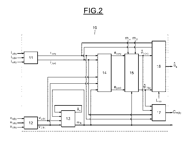
An estimation means 15 estimates the stator fluxes in the two-phase reference
frame
as a function of the speed of the rotor, of the stator resistance and of the
stator currents and
voltages in the two-phase reference frame by application of the equation Eq.7
in combination
with the equations Eq. 4 to Eq. 6. More specifically, a fourth determination
means 14
determines measurement noise and deviation rejection parameters as a function
of the stator
currents in the two-phase reference frame, of the stator voltages in the two-
phase reference
frame, of the stator resistance and of the speed of rotation of the rotor by
application of the
equations Eq. 4 to Eq. 6, and the estimation means 15 estimates the stator
fluxes as a function
of the rejection parameters determined by the fourth determination means, and
as a function of
the speed of the rotor determined by the third means.
[0049]
A fifth determination means 16 determines the position of the rotor as a
function of the
stator fluxes in the two-phase reference frame, of the stator currents in the
two-phase reference
frame and of the equivalent inductance by application of the equation Eq. 8.
If the electric machine is of synchronous type, the equivalent inductance is
set equal to the
quadratic component of the inductance of the stator.
[0050]
If the electric machine is of asynchronous type, a determination means not
illustrated
in figure 2 determines the equivalent inductance as a function of the mutual
inductance, of the
stator inductance and of the rotor inductance by application of the equation
Eq.10.
Finally, a sixth determination means 17 determines also the electromagnetic
torque as a
function of the stator fluxes in the two-phase reference frame and of the
stator currents in the
two-phase reference frame by application of the equation Eq.11.