Note: Descriptions are shown in the official language in which they were submitted.
CA 03029243 2018-12-21
WO 2018/005993 1 PCT/US2017/040335
METHOD AND SYSTEM FOR CREATING A DIAGNOSTIC VASCULAR
WINDOW
CROSS-REFERENCE TO RELATED APPLICATIONS
[0001] This application claims the benefit of U.S. Provisional Application
No.
62/357,184, filed on June 30, 2016, which is hereby incorporated by reference
in its entirety.
BACKGROUND
[0002] Blood parameters in post-surgical and in other patients requiring
critical care can
be used by health professionals to assess a patient's immediate condition.
Current practice is
to order blood sample draws from the patient and send them to the laboratory
for analysis.
Limitations exist in how much blood can be removed from critically ill and,
often, anemic
patients. Further, such blood draws only produce "snapshots" in time when the
blood is
drawn as to the condition of the patient at that point in time.
[0003] Patient conditions in critical care are often fluid and dynamic.
Deducing patient
condition from periodic blood sampling could miss one or more critical
variation if occurring
between blood samples. And, samples can be at extended time intervals because
patients in
critical care environments are there due to serious conditions and likely
cannot afford to lose
the blood volume associated with frequent blood sample draws.
SUMMARY
[0004] One aspect of the disclosure provides a method for creating a
diagnostic vascular
window to monitor a patient's blood in real time. The method includes: (a)
installing low
flow accesses to the patient's blood vessels, the low flow accesses comprising
an arterial side
access and a venous side access; (b) attaching a monitoring system to the low
flow accesses;
(c) starting blood flow to the monitoring system, the blood flowing from the
arterial side to
the venous side; and (d) measuring blood constituents from blood flowing
through the
monitoring system, wherein, during a monitoring period, a volume of fluid that
flowed out of
the arterial side access is equal to a volume of fluid that flowed into the
venous side access.
[0005] In one embodiment, attaching the monitoring system to the low flow
accesses
includes: (a) attaching an extracorporeal tubing comprised in the monitoring
system to the
low flow accesses, wherein the extracorporeal tubing is configured to
facilitate blood flow
CA 03029243 2018-12-21
WO 2018/005993 2 PCT/US2017/040335
from the arterial side access to the venous side access; and (b) attaching a
blood sensor
system comprised in the monitoring system to the extracorporeal tubing.
[0006] In one embodiment, the blood sensor system includes one or more
emitters and
one or more sensors.
[0007] In one embodiment, the one or more emitters are optical emitters and
the one or
more sensors are optical sensors, and the blood sensor system further
comprises a blood
chamber, the blood chamber configured to provide a location where blood within
the blood
chamber can be viewed using the optical emitters and the optical sensors.
[0008] In one embodiment, the optical emitters are light emitting diodes
(LEDs) or lasers.
[0009] In one embodiment, the optical sensors are photodiodes.
[0010] In one embodiment, the one or more emitters are acoustic emitters
and the one or
more sensors are acoustic sensors.
[0011] In one embodiment, the monitoring system measures blood parameters
comprising
hematocrit, change in blood volume, and oxygen saturation.
[0012] In one embodiment, the low flow accesses are peripherally inserted
central
catheter (PIC) lines or intravenous needles.
[0013] In one embodiment, the low flow accesses support blood flowrates
between 5
milliliters per minute and 50 milliliters per minute.
[0014] In one embodiment, the low flow accesses support blood flowrates
between 10
milliliters per minute and 20 milliliters per minute.
[0015] Another aspect of the disclosure provides a system for monitoring a
patient's
blood in real time. The system comprises: (a) a blood pump configured to pump
blood from
an arterial side access to a venous side access, the arterial side access and
the venous side
access being low flow accesses; (b) tubing coupled to the blood pump, the
tubing configured
to carry extracorporeal blood from the arterial side access to the venous side
access at a
flowrate determined by the blood pump; and (c) a blood sensor system coupled
to the tubing,
the blood sensor system configured to measure blood constituents of the
extracorporeal blood
flowing through the tubing; wherein the system is configured such that, during
a monitoring
period, a fluid volume that flowed from the arterial side access is equal to a
fluid volume that
flowed into the venous side access.
[0016] In one embodiment, the blood sensor system includes one or more
emitters and
one or more sensors.
[0017] In one embodiment, the one or more emitters are optical emitters and
the one or
more sensors are optical sensors, and the blood sensor system further includes
a blood
CA 03029243 2018-12-21
WO 2018/005993 3 PCT/US2017/040335
chamber, the blood chamber coupled to the tubing to provide a location where
blood within
the blood chamber can be viewed using the optical emitters and the optical
sensors.
[0018] In one embodiment, the optical emitters are LEDs or lasers, and the
optical
sensors are photodiodes.
[0019] In one embodiment, the one or more emitters are acoustic emitters
and the one or
more sensors are acoustic sensors.
[0020] In one embodiment, the low flow accesses are PIC lines or
intravenous needles.
[0021] In one embodiment, the low flow accesses support blood flowrates
between 5
milliliters per minute and 50 milliliters per minute.
[0022] In one embodiment, the low flow accesses support blood flowrates
between 10
milliliters per minute and 20 milliliters per minute.
[0023] In one embodiment, the system further includes: (a) a controller
configured to
activate and determine speed of the blood pump; and (b) a power source
configured to be
replaceable, wherein the power source is selected based on a length of a
medical procedure of
the patient.
BRIEF DESCRIPTION OF THE DRAWINGS
[0024] The present invention will be described in even greater detail below
based on the
exemplary figures and embodiments. The invention is not limited to the
exemplary
embodiments. All features described and/or illustrated herein can be used
alone or combined
in different combinations in embodiments of the invention. The features and
advantages of
various embodiments of the present invention will become apparent by reading
the following
detailed description with reference to the attached drawings which illustrate
the following:
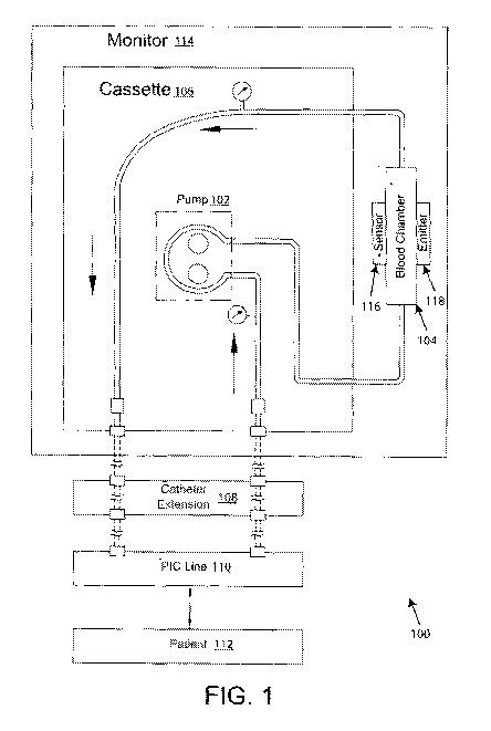
[0025] FIG. 1 illustrates a high level system diagram of a monitoring
system in an
exemplary environment;
[0026] FIG. 2 illustrates an example embodiment for a surgical and/or
Intensive Care
Unit (ICU) application of the high level system diagram shown in FIG. 1;
[0027] FIG. 3 is a perspective illustration of one of the viewing sides of
one embodiment
of a low flow optical blood chamber;
[0028] FIG. 4 illustrates an example embodiment of an optical sensor clip
assembly
installed on an example embodiment of a low flow optical blood chamber;
[0029] FIG. 5 illustrates an exemplary diagram of a monitor and its
interfaces with
function of the interfaces under software control; and
CA 03029243 2018-12-21
WO 2018/005993 4 PCT/US2017/040335
[0030] FIG. 6 illustrates an example of a process performed with the
monitoring system
for monitoring blood volume during a surgery procedure with follow-up in a
post-surgical
environment such as in the ICU.
DETAILED DESCRIPTION
[0031] In some medical situations, real-time access to a patient's blood
stream is
desirable in order to monitor specific blood parameters. Embodiments of the
disclosure
provide for real-time access to a patient's blood stream.
[0032] Conventional methods and devices have not provided a way to pull
extracorporeal
blood into a blood lab for continuous measurement of key blood constituents.
Conventional
blood draws and monitoring are invasive and are not conducted in real time.
Due to its
limitations, conventional blood draws are sometimes not conducted at all. For
example, for
patients in an intensive care unit (ICU), to obtain information about
hematocrit and/or
hemoglobin, a patient's blood is typically drawn into a test tube and
laboratory analysis is
performed thereon. If the patient cannot tolerate a pulse-oximeter on their
finger or toe, a
similar blood draw may be performed and measured on a CO-oximeter located in
the ICU.
This process may require that the CO-oximeter be in the ICU, and it may also
dictate very
careful handling of the blood sample because movement and agitation of blood
samples
causes immediate oxygen changes. Therefore, any oxygen measurement must be in
close
proximity to the patient.
[0033] There are also situations where medical practitioners are relying
solely on
guesswork/estimation with respect to blood characteristics. For example, in
cases when an
organ replacement is performed, an anesthesiologist may be required to inject
the patient with
a number of pharmaceuticals and/or solutions to keep the patient stable. The
injections add
blood volume, and this blood volume must be later removed by the medical
practitioner via
the administration of diuretics in order to place the patient's blood volume
after transplant
within a given tolerance of the patient's original blood volume. Some medical
opinions
indicate that if the original blood volume is not substantially achieved that
the success of an
organ transplant can be in jeopardy.
[0034] Embodiments of the disclosure provide an advanced hemodynamic
monitoring
method and system that clinical staff and physicians can use to monitor blood
constituents
and parameters in a continuous manner. The system may be attached to a patient
through use
of a commonly used venous Peripherally Inserted Central Catheter ("PICC" or
"PIC") line.
A small amount of blood is pumped out of the patient through the "arterial"
side of the PIC
CA 03029243 2018-12-21
WO 2018/005993 5 PCT/US2017/040335
line, routed through a single use, sterile blood chamber and back into the
patient through the
"Venous" side of the PIC line. By using this technique, a sample of the
patient's circulatory
system is extended outside the body where observations can be taken without
incurring any
blood loss. Though a number of sensor systems (acoustical, ultrasonic,
optical, etc.) can be
interfaced to this extracorporeal blood loop, in a preferred embodiment, an
optical sensor
which views the blood through a uniform, single use blood chamber for
continuous
constituent measurements using different wavelengths of light is used. Since
blood is
circulated from and back into the patient's body, there is no blood loss as in
conventional
methods where blood samples are extracted from the patient and taken to a lab.
Additionally,
selected blood parameters are monitored continuously, allowing for observation
of dynamic
changes in the patient's condition. A monitoring system according to some
embodiments of
the disclosure can facilitate guided hemodynamic interventions required to
stabilize patients
and optimize outcomes. In some embodiments, the system can measure at least
real-time
hematocrit (HCT) and oxygen saturation (SAT). Based on the HCT measurements,
change in
blood volume (BV) and hemoglobin (Hb) can be calculated and displayed. Other
blood
parameters (e.g. platelets, carboxyhemoglobin, etc.) can be measured by
introduction of
additional wavelengths with the attendant calibrations.
[0035] A system according to some embodiments of the disclosure may be used
in the
detection of loss of fluid from a patient's intravascular compartment into the
patient's
interstitial compartment and third spaces (e.g., the peritoneal cavity and gut
lumen). The loss
of fluid occurs in many medical situations (e.g., postoperative period of
abdominal surgery,
liver cirrhosis, congestive heart failure, intestinal ischemia). Loss of fluid
from the
intravascular compartment into the interstitial compartment and third spaces
is also a major
component of sepsis. As a result, septic patients require large volumes of
replacement fluid in
order to maintain their intravascular blood volume. The system may monitor
blood volume
changes in real time, allowing for correct diagnosis of the fluid changes and
facilitating the
clinical decisions on how to treat the patient.
[0036] A system according to some embodiments of the disclosure may also be
used
where the opposite situation can be problematic. For example, infusion of
drugs and other
fluids based on anesthesia practices during surgery can add an unquantified
blood volume to
the patient. Some studies have shown that in the case of transplant surgery
that patient blood
volume which departs significantly from the blood volume at the commencement
of surgery
may place the transplanted organ in jeopardy. Determining the correct type and
dose of
diuretic drugs is a challenge, and there is currently no simple way to
evaluate the overall
CA 03029243 2018-12-21
WO 2018/005993 6 PCT/US2017/040335
effect on the patient's blood volume other than estimating the fluid amount
added during the
procedure and then monitoring urine output afterward.
[0037] Embodiments of the disclosure may also be used for hemodynamic
monitoring
during treatment and care in other situations where hemodynamic compromise is
present.
Examples of these situations include shock due to hypovolemia, trauma, heart
failure,
neurogenic shock and acute myocardial infarction (MI) with cardiogenic shock.
Hemodynamic monitoring may also benefit situations of increased metabolic
demands,
requiring increased blood-flow and perfusion, for example, sepsis, burns,
major surgery,
including pre, intra, and post-operative. These example situations call for
efficient clinical
decision making taking into account rapid hemodynamic fluctuations which is
lacking in
conventional approaches, for example, blood sample draw, blood gas meters, and
so on.
[0038] Current hemodynamic monitoring places an emphasis on a patient's
pulse and
blood pressure. Blood pressure can relate to perfusion to the brain and the
heart. However, it
does not help define perfusion to renal and mesenteric beds. Additionally,
coronary and
cerebral ischemia blood pressure thresholds are variable. The patient's pulse
and blood
pressure does not capture enough information in dealing with the above
identified situations
where clinicians need to make, revisit and modify decisions on such things as
fluids
resuscitation, dosages of cardiac agonists, peripheral vascular acting agents,
for example,
pressors, and diuretics. These decisions can influence the incidence of
complications,
duration of ventilation, a requirement for interventions (for example,
hemodialysis and
chemotherapy), the use of continuous renal replacement therapy (CRRT), the
length of
hospital stay and even mortality rates.
[0039] The following example embodiment of a blood monitoring system in
this present
disclosure provides for non-invasive (other than a standard PIC line use) and
real-time
monitoring of blood characteristics thereby avoiding a need for successive,
invasive blood
draws (particularly for ICU blood monitoring) and eliminating guesswork from
blood volume
adjustment procedures.
[0040] The ICU environment is used as an example since in many cases an ICU
patient is
already anemic, therefore, lacking in red blood cell volume which is the
primary carrier of
oxygen to the body and vital organs. Conventional blood draws result in
removal of red
blood cell volume as one of the constituents in the blood sample. Therefore,
the number of
blood draws are limited in such a patient because he or she may not be able to
tolerate any
red blood cell volume loss. The normal regeneration of red cell volume in a
healthy patient
usually spans several weeks. This regeneration rate limits the number of blood
samples that
CA 03029243 2018-12-21
WO 2018/005993 7 PCT/US2017/040335
may be obtained from an ICU patient, and therefore, limits the resolution of
the patient's
blood profile. In conventional blood draw monitoring, any dynamic occurrence
in the blood
(from an occurrence of spontaneous internal bleeding to an expected reduction
in blood
volume due to prescribed diuretic drugs) can only be approximated with limited
samples or
such dynamics can be missed entirely.
[0041] Embodiments of the disclosure increase resolution of a patient's
blood profile by
recirculating the patient's blood, thus requiring no blood draw or loss.
Further, the
circulating blood can be observed continuously in real time to monitor various
blood
parameters of interest. As such, a diagnostic vascular window is created for
measuring
constituents and parameters in a patient's blood.
[0042] FIG. 1 illustrates a blood composition monitor 114 or monitoring
system in an
exemplary environment 100 usable with exemplary embodiments of the disclosure.
The
illustrated environment 100 may be in the ICU, surgery suite, recovery room,
or any place
examination of a patient's real-time blood condition is deemed valuable for
clinical
diagnostics. A pump 102 creates the extracorporeal blood flow through the
blood chamber
104. In this illustrated embodiment, the pump 102 engages a cassette 106 that
includes inlet
and outlet blood flow lines for coupling to the blood chamber 104 on one side
of the cassette
106 and to a catheter extension line set 108 leading to a PIC line 110
inserted into the patient
112. The monitor 114 receives the cassette 106 such that the inlet line from
the arterial side
of the catheter extension lines 108 connects with the pump 102 to draw blood
from the
patient's PIC line 110 to the input of the blood chamber 104 (bottom in FIG.
1). The output
of the blood chamber 104 (top in FIG. 1) connects to a return line back
through the cassette
106 and through the venous side of the extension lines 108 for returning the
blood to the
patient 112 through the venous side of the PIC line 110. The catheter
extension lines allow
the remote blood connection of the monitor system 114 to the PIC line 110 in
the patient 112.
[0043] FIG. 2 illustrates additional details of an exemplary embodiment of
the overall
system shown in FIG 1. Beginning at the patient 10, an arterial (input) blood
connection to
the monitor system 114 is provided. In this example, the arterial line 18 is
connected to the
arterial side of a PIC line inserted into the patient 10. Connections 16 and
26 are the arterial
and venous sides of the PIC line, respectively. Blood is pulled from the
patient 10 via arterial
line 18 by the pump 102. Arterial line 18 continues after the pump to the
input of an optical,
single use blood chamber 104 and then the blood returns to the patient 10
through venous line
24 to the connection 26 on the venous side of the PIC line.
CA 03029243 2018-12-21
WO 2018/005993 8 PCT/US2017/040335
[0044] Unlike dialysis accesses where the patient requires a surgical
procedure to implant
a shunt (often made of Gore-Tex ) or to grow a thickened vein structured
termed a fistula
where needle access is frequently (typically three times per week) inserted
into the patient,
the PIC line is inserted for short term treatment associated with a single
surgery or procedure.
In dialysis use, the extracorporeal blood circuit is primarily used for
dispensing treatment
through filtering the blood of impurities. And in dialysis use, blood
flowrates found in shunts
are upward of 1 liter per minute and high pressures associated with such
flowrates are
common and must be dealt with. Dialysis uses high flowrates since all blood
circulating
through a patient needs to be filtered, as such, all of the patient's blood is
pumped out while
recirculating it for filtering. In contrast to a dialysis access, in the short
term treatment, a
simple sample loop of the patient's blood coming from a lower flow vein
without significant
pressure provides an observation window to the core body functions as
indicated by changes
in blood constituents observed in real time. Accesses for creating a
diagnostic vascular
window according to embodiments of the disclosure are different from those
used during
dialysis. Dialysis accesses are punctured with significantly sized needles to
support the high
blood flow (upwards of 500 milliliters per minute in the United States). Veins
or PIC lines
are not used as accesses in dialysis since repeated puncturing may damage the
access. The
diagnostic window does not need to have all the patient's blood pumped out
(only a sample),
therefore, a low flow rate is capable of being used with the monitoring system
114.
[0045] Other examples of low flow accesses exist, such as, that used for
assisting
temporary or partial kidney failure with CRRT. CRRT is a slow dialysis
treatment often
given in the ICU. Another example of a low flow access is that used for
treating congestive
heart failure, such as, accesses used with the Aquadex FlowFlex system. The
CRRT and
Aquadex FlexFlow examples dispense one or more treatments rather than act as
a window
into a patient's blood system. In these examples where low flow accesses are
used,
treatments are administered once blood is pulled from the body, thereby
providing one or
more ways where a patient may gain or lose fluid. In contrast to embodiments
of the
disclosure, treatment is not administered, thus the amount of fluid exiting
the arterial side of
an access is the same amount of fluid entering the venous side of an access.
[0046] In one example, a low flow venous access supports blood flowrates
between 5
milliliters per minute and 50 milliliters per minute. A lower limit is placed
on the blood flow
rate based on concerns of blood coagulation if blood flow is too low. In
another example, a
low flow access supports blood flowrates between 10 milliliters per minute and
20 milliliters
per minute. These low flow rate examples when contrasted with high flow rates
upward of
CA 03029243 2018-12-21
WO 2018/005993 9 PCT/US2017/040335
500 milliliters per minute of arterial blood during dialysis do not have
similar risks
associated. As already described, the high flow rates of dialysis introduce
high pressures that
require special accesses that support large needles to support such blood
flow. In addition, a
human body has about 5 L to 6 L of blood, so when complications arise and a
dialysis access
needle is pushed out, the patient is at risk to bleed out quickly. In
contrast, the low flow
access does not deal with such high pressures due to the venous access
approach and high
flow rates are not used so a patient is not at risk to bleed out if the venous
needle becomes
dislodged and not observed.
[0047] In some embodiments, the PIC line connections 16 and 26 in FIG. 2
providing
accesses for blood to be pulled from the patient 10 and returned to the
patient 10 may be
replaced with two intravenous (IV) needles, strategically placed to feed blood
to the
measurement blood chamber 104. The blood in the blood chamber 104 can be
viewed in real
time as part of the patient's circulatory system, and the minimum volume of
blood viewed
fills the blood chamber 104.
[0048] An example of a blood chamber that may be used as the blood chamber
104 is the
blood chamber 12 shown in FIG. 3 and disclosed in U.S. Pat. No. 8,333,724
entitled "Low
Flow Optical Blood Chamber" which is incorporated by reference in its
entirety. The blood
chamber 12 may include two molded parts, namely a chamber body 24 and a lens
body 26.
In one embodiment, the lens body 26 may be sonically welded to the chamber
body 24. In
another embodiment, the lens body 26 may be secured to the chamber body 24
with medical
grade adhesive. Other methods of securing the lens body 26 to the chamber body
24 may be
employed provided that the lens body 26 be attached to the chamber body 24 to
provide a
leak-free blood flow chamber 12. For this reason, there should be sufficient
dimensional
interference between the lens body 26 and the chamber body 24.
[0049] The sensor unit 116 and the emitter unit 118 may be, for example,
provided as a
single sensor/emitter assembly. In some embodiments, the sensor unit 116 is a
photosensor
116 and the emitter unit 118 is a light emitter 118. The physical mounting and
mating of the
blood chamber 104 and the photosensor 116 and the light emitter 118 can be,
for example,
associated with a mounting fixture that is part of a cassette 106. However,
the photosensor
116 and the light emitter 118 are usually not disposable or manufactured to be
disposable,
and therefore, are intelligent enough to hold calibration information of parts
of a disposable
cassette 106.
[0050] In one embodiment, the blood chamber 104 and the photosensor 116 and
the light
emitter 118 interface is as provided by the CRIT-LINE monitoring system as
shown in FIG.
CA 03029243 2018-12-21
WO 2018/005993 10 PCT/US2017/040335
4. The CRIT-LINE monitoring system approach is disclosed in U.S. Pat. No.
9,173,988
entitled "Sensor Clip Assembly for an Optical Monitoring System" which is
incorporated by
reference in its entirety. Tubing 14 is attached to the blood chamber 12. The
optical sensor
clip assembly 10 is an embodiment of the sensor 116/the emitter 118 unit of
FIG. 1. In an
exemplary embodiment, the tubing 14 is 1/8" clear, medical grade polypropylene
tubing
appropriate for use in the peristaltic pump. In an embodiment, the sensor clip
assembly 10
includes two arms 16A, 16B forming a spring-biased, jaw-like structure. The
handles 22A,
22B on the sensor assembly arms 16A, 16B can be squeezed together against the
spring bias
to spread the heads 18A, 18B of the sensor assembly to install or remove the
sensor assembly
on the blood chamber 12.
[0051] It will be appreciated that if the monitoring system 114 is optical
technology
based, the type of photosensor and light emitter can be varied based the blood
parameters of
interest. For example, the photosensor can be a silicon photodiode with
sensitivity in the
wavelengths from 500nm to 900nm. The light emitter could contain two light
emitting
diodes (LEDs) of 660nm and 800nm which can be measured by the photosensor. If
the two
LEDs are alternately measured at a fast rate (e.g. 300 times per second per
wavelength) then
Beer's Law can be used to extract the molar concentration of both oxygenated
hemoglobin
(660nm) and isobestic hemoglobin (800nm). The ratio of these two
concentrations allow the
hemoglobin term to divide out and leave only the oxygen content of the blood.
A calibration
equation can be applied to give accurate blood oxygen saturation readings.
Other types of
sensors, such as, indium gallium arsenide (InGaAs) detectors can be used for
longer
wavelengths, and lasers, for example, may be used for light emitters.
[0052] In some embodiments of this monitoring system, the sensor system
(blood
chamber 104, sensor unit 116, and emitter unit 118) may be arranged such that
the blood
chamber 104 is replaced by a section of tubing (for example, polyurethane)
with repeatable
sound characteristics that can be mass produced. The sensor unit 116 may then
be replaced
with a sound transducer, and the emitter unit 118 may be replaced with a sound
emitter with
ultra-sonic frequencies tuned to measure the viscosity or density of the
blood. The acoustic
measurement of the viscosity of blood can be equated to a level of hemoglobin
content.
[0053] While optical and acoustic technologies are described for use in the
sensor system,
it can be appreciated that other types of sensors can be adapted to probe
blood flowing from
the body to measure various blood parameters for real-time monitoring without
blood loss.
In some embodiments, hybrid systems of different sensors are also possible.
CA 03029243 2018-12-21
WO 2018/005993 11 PCT/US2017/040335
[0054] FIG. 5 illustrates an exemplary diagram of the blood monitor 114
controller
system and power source 120. When used with surgical patients, the central
controller and
power source 120 is designed not to interfere with or not to be cumbersome to
the patient or
the clinical environment. The power source may be comprised of batteries such
as one or
more AA size cells. Due to the nature of an operating room in a healthcare
facility or a
hospital, the power source is designed to be sealed. The power source may be
designed to be
sealed for use in environments where gases are present. In some embodiments,
the power
source will be rechargeable. In some embodiments, when an external charging
source is
connected to the monitoring system 114, the external charging source will not
only recharge
the power source but also provide power to the monitor system 114. The power
source may
be constructed in multiple capacities and selected depending on length of the
patient's
procedure. In some embodiments, the power source is replaceable during the
patient's
procedure without data loss (a so called "hot swap").
[0055] The central controller may include one or more processors or
microcontrollers and
non-transitory computer readable media with programmed instructions to perform
tasks
associated with managing the monitoring system 114. The central controller 120
manages
the tasks of the monitor system 114. It will activate the blood pump 120 to
bring blood from
the patient to the blood sensor system and chamber. The blood sensor system
identified as
being, for example, in FIG. 1, the blood chamber 104, the sensor 116, and the
emitter 118.
The central controller 120 not only activates the blood pump 120, but may also
determine and
control the speed of the blood pump 102. The blood pump 102 may be powered by
the
power source.
[0056] The central controller and power source 120 also provides power and
control
signals to sensor elements 116 and 118 to manage which sensor elements in
sensor 116 and
which emitter elements in emitter 118 are turned ON and OFF. The central
controller and
power source 120 also determine the timing of measurement sampling, hence how
frequent a
measurement is taken. In an embodiment where the blood sensor system comprises
one or
more LED elements as emitter 118 and one or more photodetector elements as
sensor 116,
the transmitting LED(s) 118 and receiving photodetector(s) 116 are controlled
by the central
controller and power source 120. It is possible for some embodiments of this
technology for
the system to use continuous wave signal(s) as opposed to pulsed sampled
signals.
[0057] The central controller and power source 120 can power and control a
parameter
display 130 in the form of a liquid crystal display (LCD) read-out or other
form of graphical
CA 03029243 2018-12-21
WO 2018/005993 12 PCT/US2017/040335
or text display. The data may be presented in either text or graphic format
with calculations
performed by the central controller 120 to drive the display.
[0058] In addition to or as an alternate method, the central controller and
power source
120 can drive a wireless interface 140 communications link to a remotely
located display. If
attached to a surgical patient, the footprint of the entire monitoring system
114 may be
miniaturized to the point of non-interference with clinical procedures and
access to the
patient. In such cases, an on-board display 130 may not be practical.
Furthermore, a wireless
link 140 using Bluetooth , Wi-Fi, Zigbee or other similar technology
protocols can
facilitate a large screen display located in a convenient and visible part of
the clinical suite,
ICU or operating room. The entire monitoring system 114 can remain small, out
of the way,
power independent and still produce valuable blood parameter and patient
condition data on a
large readable screen in the operating room. The monitoring system 114 may be
moved to
recovery where external power can be applied to the system and a display in
that room may
be updated to continue showing the history of the procedure.
[0059] The monitoring system 114 may be used in other situations not
associated with
surgery. It can be used with patients in the ICU suffering from any malady
where
observation of blood parameters in real time are of value in monitoring the
patients'
conditions.
[0060] FIG. 6 is a flow diagram illustrating a process 600 of monitoring
blood parameters
using a monitoring system 114 according to some embodiments of the disclosure.
Step 602
indicates the beginning of surgery. At step 604, a PIC line is inserted into
the patient. The
PIC line is either pre-installed or installed in the patient.
[0061] At step 606, the monitoring system 114 and the blood sensor system
(104, 116,
and 118) are connected to the PIC line connectors 16 and 26. In an embodiment,
the
monitoring system 114 operates on battery power, and the blood sensor system
includes
optical components. The blood pump 102 and the blood chamber 104 are attached
to the
arterial and venous ports of the PIC line, connectors 16 and 26, as
appropriate. The optical
emitter(s) 118 and optical sensor(s) 116 are seated onto the viewing area of
the blood
chamber 104.
[0062] At step 608, blood flow is started by the central controller and
power source 120.
The central controller engages the blood pump 102 to pump blood from the
patient from the
arterial port of the PIC line to the venous port of the PIC line. An
extracorporeal tubing
connecting both ports of the PIC line provides the monitoring system 114
access to the blood.
CA 03029243 2018-12-21
WO 2018/005993 13 PCT/US2017/040335
[0063] At step 610, one or more blood parameters are measured during
surgery. For
example, the blood sensor system (104, 116, and 118) obtains data on blood
present in the
blood chamber 104 by emitting light from the optical emitter(s) 118, having
the emitted light
pass through the blood in the blood chamber 104, and sensing the light
received at the optical
sensor(s) 116. Data obtained by the blood sensor system is processed by the
central
controller and power source 120 and may be transferred to a local display 130
(if installed in
monitoring system 114) and/or sent wirelessly to a remote display to be viewed
by
individuals in the procedure room. In some embodiments, once data is being
received by the
central controller and power source 120 and verified as correct, the monitor
system 114 is
small enough to be placed out of the way, where it is unobtrusive during
subsequent medical
procedures. In an example, the blood parameter being measured is HCT, and from
HCT
values, change in blood volume is measured as surgery proceeds. A graphical
screen may
show the progress of blood volume changes over time. Monitoring of the change
in blood
volume during the surgery procedure can indicate to the surgical team how the
procedure is
advancing. For example, a sudden drop in blood volume could indicate
unexpected blood
loss.
[0064] At step 612, when the surgery is complete, the patient may be moved
to recovery
where the monitoring system 114 will remain in place and active. In recovery,
effects of
recovery medicines, such as, diuretic drugs, can be monitored to ensure that
added fluids
during surgery are being properly removed to return the patient's blood volume
close to the
patient's initial blood volume. While the patient is in recovery and in the
post surgery phase,
a small, low current charger may be attached to the monitoring system 114 to
recharge the
battery in the central controller and power source 120.
[0065] At step 614, the monitoring system 114 may be left in place until
the physician is
satisfied that the patient is stable, and there is no longer utility in
monitoring the blood
volume changes. HCT measurement and monitoring is used as an example to
illustrate steps
involved in process 600. It is understood that other parameters (including
multiple
parameters at the same time) can be monitored with the measurement system 114.
[0066] As examples, the blood monitoring system 114 can monitor loss of
fluid from the
intravascular compartment into the interstitial compartment and third spaces.
That is,
patient's progress and response to antibiotic therapy can be monitored to help
optimize and
minimize the complications of IV fluid therapy. In addition, the monitoring
system 114 may
be used for investigating new therapies introduced to treat septic states.
Some other
examples of measureable metrics include (but are not limited to): (1) Absolute
HCT, and
CA 03029243 2018-12-21
WO 2018/005993 14 PCT/US2017/040335
estimated hemoglobin which is useful to monitor for blood loss, anemia and
patient response
to transfusions; (2) Change in blood volume for evaluating third spacing in a
sepsis situation,
for detection of blood loss and/or evaluation of dialysis, CRRT and similar
fluid management
treatments for effectiveness; (3) Oxygen saturation is a key physiological
parameter, which is
a useful indicator for organ failure. The diagnostic capability of oxygen
saturation depends on
whether it is measured in arterial or venous blood. When measured in arterial
blood, a low
oxygen saturation is most frequently due to respiratory disorders. Low venous
oxygen
saturation is frequently seen with cardiac failure, in sepsis and major bleeds
such as aortic
aneurysm and rupture of the spleen; and (4) With the use of dye marker
infusions into the
patient's blood stream, parameters such as liver function can be determined.
[0067] Embodiments of the disclosure may be used to determine various real-
time
metrics indicative of a patient's body fluid condition. The real-time metrics
may be
determined using a diagnostic vascular window. The diagnostic vascular window
may be
created by installing low flow accesses to the patient's blood vessels, the
low flow accesses
including an arterial side access and a venous side access. A monitoring
system according to
some embodiments of the disclosure may be attached to the low flow accesses
and blood may
flow from the arterial side access to the venous side access. The monitoring
system may then
measure blood constituents from blood flowing from the arterial side access to
the venous
side access through the monitoring system. Since no treatment is being
administered through
the arterial side and venous side accesses of this window system and no
treatment is being
administered at the related monitoring system, the volume of fluid flowing out
of the arterial
side access during the course of a monitoring period is equal to a volume of
fluid flowing
back into the venous side access of the PIC line (it will be appreciated that
the term "equal" is
used herein to mean that the monitoring system is a closed loop circuit and
that no fluid is
added or removed due to treatment being performed via the extracorporeal blood
being
circulated out from arterial access). The monitoring period may be, for
example, a period of
time beginning when measurement begins and ending when measurement is stopped,
or may
be, for example, a period of time beginning when the accesses to the patient's
blood vessels
are connected and ending when the accesses to the patient's blood vessels are
removed.
[0068] To the extent that treatment involving insertions into a patient's
circulatory may
be needed, such treatments may be administered through other accesses to the
patient's
circulatory system.
[0069] In one example, an extracorporeal tubing included in the monitoring
system
facilitates blood flow from the arterial side access to the venous side access
of the PIC line,
CA 03029243 2018-12-21
WO 2018/005993 15 PCT/US2017/040335
and the monitoring system attaches a blood sensor system to the extracorporeal
tubing to
measure blood parameters.
[0070] In another example, a blood chamber may be coupled to the low flow
accesses
using a blood chamber placed in the path of the tubing. The blood chamber
provides a
window where a blood sensor system of the monitoring system measures blood
parameters.
[0071] All references, including publications, patent applications, and
patents, cited
herein are hereby incorporated by reference to the same extent as if each
reference were
individually and specifically indicated to be incorporated by reference and
were set forth in
its entirety herein.
[0072] The use of the terms "a" and "an" and "the" and "at least one" and
similar
referents in the context of describing the invention (especially in the
context of the following
claims) are to be construed to cover both the singular and the plural, unless
otherwise
indicated herein or clearly contradicted by context. The use of the term "at
least one"
followed by a list of one or more items (for example, "at least one of A and
B") is to be
construed to mean one item selected from the listed items (A or B) or any
combination of two
or more of the listed items (A and B), unless otherwise indicated herein or
clearly
contradicted by context. The terms "comprising," "having," "including," and
"containing"
are to be construed as open-ended terms (i.e., meaning "including, but not
limited to,") unless
otherwise noted. Recitation of ranges of values herein are merely intended to
serve as a
shorthand method of referring individually to each separate value falling
within the range,
unless otherwise indicated herein, and each separate value is incorporated
into the
specification as if it were individually recited herein. All methods described
herein can be
performed in any suitable order unless otherwise indicated herein or otherwise
clearly
contradicted by context. The use of any and all examples, or exemplary
language (e.g., "such
as") provided herein, is intended merely to better illuminate the invention
and does not pose a
limitation on the scope of the invention unless otherwise claimed. No language
in the
specification should be construed as indicating any non-claimed element as
essential to the
practice of the invention.
[0073] Preferred embodiments of this invention are described herein,
including the best
mode known to the inventors for carrying out the invention. Variations of
those preferred
embodiments may become apparent to those of ordinary skill in the art upon
reading the
foregoing description. The inventors expect skilled artisans to employ such
variations as
appropriate, and the inventors intend for the invention to be practiced
otherwise than as
specifically described herein. Accordingly, this invention includes all
modifications and
CA 03029243 2018-12-21
WO 2018/005993 16
PCT/US2017/040335
equivalents of the subject matter recited in the claims appended hereto as
permitted by
applicable law. Moreover, any combination of the above-described elements in
all possible
variations thereof is encompassed by the invention unless otherwise indicated
herein or
otherwise clearly contradicted by context.