Note: Descriptions are shown in the official language in which they were submitted.
UNDERWATER ENERGY HARVESTING DRONE AND METHOD FOR
OPERATION
BACKGROUND INFORMATION
Field
Implementations shown in the disclosure relate generally to underwater
unmanned
vehicles (UUV) and more particularly to UUVs employing thermoelectric systems
to
generate electrical power using temperature differential in the environment in
which the UUV
operates.
Background
UUVs are employed for various tasks in undersea exploration, environmental
monitoring and security operations. Operational profiles for the UUVs make
extended
operating capability with limited refueling requirements attractive. Deep
oceans are the ideal
environment for covert military operations. Such operations are often relying
on UUVs for
combat and reconnaissance missions.
Certain prior art UUVs employ thermal gradients in the ocean thermocline for
energy
generation or propulsive effects. However, the thermocline asymptotically
approaches a
temperature of about 3.5 degrees Celsius at about 1000 Meters and below. UUVs
relying on
the gradient in the thermocline are therefore energy starved in the deep sea
environment.
Consequently, UUVs must frequently surface for refueling increasing their
visibility and
placing the UUV at potential risk of collision or course interruption with
surface ships.
SUMMARY
Exemplary implementations provide an underwater energy harvesting drone having
a
primary hull to be submersibly received in ocean water and a plurality of
thermoelectric
modules, each module of said plurality of thermoelectric modules having a
first operational
interface in thermal contact with the primary hull. A thermal transfer element
is in contact
with a second operational interface on the plurality of thermoelectric modules
and an
electrical power storage device is connected to the plurality of
thermoelectric modules.
Positioning of the submersible primary hull to create a thermal gradient
between the primary
hull and the thermal transfer element induces electrical power generation by
the
thermoelectric modules thereby charging the electrical power storage device.
CA 3029964 3029964 2019-01-14
The exemplary implementations allow a first method for operation of an
unmanned
underwater vehicle (UUV) wherein cold ocean water is entrained into an
internal storage tank
in a first position. The internal storage tank is then placed in a second
position to store the
cold ocean water. The UUV is navigated to a hydrothennal vent location placing
a primary
hull into a "hot zone" compared to surrounding ocean water. Power is generated
with
thermoelectric modules based on the theimal gradient between the primary hull
and internal
storage tank to charge an electrical power storage.
The exemplary implementations allow a second method for operation of an
unmanned
underwater vehicle (UUV) wherein the submerged UUV is surfaced to expose a
heat
dissipater to the air. Thermoelectric modules are operated to provide
electrical energy
generation for charging of an electrical power storage device employing
temperature
differential between a primary hull immersed in ocean water and the heat
dissipater in
convective contact with the air.
The exemplary implementations allow an underwater energy harvesting drone
comprising: a primary hull to be submersibly received in ocean water; a
plurality of
thermoelectric modules, each module of said plurality of thermoelectric
modules having a
first operational interface in thermal contact with the primary hull; a
thermal transfer element
in contact with a second operational interface on the plurality of
thermoelectric modules,
wherein the themial transfer element comprises an internal storage tank
adapted to receive
cold ocean water in a first position and store the cold ocean water in a
second position; an
electrical power storage device connected to the plurality of thermoelectric
modules; wherein
positioning of the primary hull to create a thermal gradient between the
primary hull and the
thermal transfer element induces electrical power generation by the
thermoelectric modules
thereby charging the electrical power storage device; an electrical motor
connected to receive
power from the electrical power storage device; a propulsor driven by said
electrical motor;
control planes engaged to the primary hull; and a control system adapted to
provide control
signals to the electrical motor and control planes pursuant to a navigational
profile, wherein
the navigational profile locates the primary hull in a hot plume of a
hydrotheanal vent.
The exemplary implementations allow an underwater energy harvesting drone
comprising: a primary hull to be submersibly received in ocean water; a
plurality of
thermoelectric modules, each module of said plurality of thermoelectric
modules having a
first operational interface in thermal contact with the primary hull; a
thermal transfer element
in contact with a second operational interface on the plurality of
thermoelectric modules,
wherein the theimal transfer element comprises a heat dissipater mounted to
and extending
-2-
Date Recue/Date Received 2022-06-07
from a top surface of the primary hull; an electrical power storage device
connected to the
plurality of theinioelectric modules; wherein positioning of the primary hull
to create a
thermal gradient between the primary hull and the thermal transfer element
induces electrical
power generation by the thermoelectric modules thereby charging the electrical
power
storage device; an electrical motor connected to receive power from the
electrical power
storage device; a propulsor driven by said electrical motor; control planes
engaged to the
primary hull; and a control system adapted to provide control signals to the
electrical motor
and control planes pursuant to a navigational profile, wherein the
navigational profile causes
selective surfacing of the primary hull to expose the heat dissipater from the
ocean water.
The exemplary implementations allow an underwater energy harvesting drone
comprising: a primary hull to be submersibly received in ocean water, wherein
the primary
hull comprises an upper portion and a lower portion, said upper portion and
lower portion
separated by an insulating barrier; a plurality of thermoelectric modules,
each module of said
plurality of theinioelectric modules having a first operational interface in
thermal contact
with the primary hull; a thermal transfer element in contact with a second
operational
interface on the plurality of thermoelectric modules, wherein the upper
portion comprises the
thermal transfer element; an electrical power storage device connected to the
plurality of
thermoelectric modules, wherein positioning of the primary hull to create a
thermal gradient
between the primary hull and the thermal transfer element induces electrical
power
generation by the thermoelectric modules thereby charging the electrical power
storage
device; an electrical motor connected to receive power from the electrical
power storage
device; a propulsor driven by said electrical motor; control planes engaged to
the primary
hull; and a control system adapted to provide control signals to the
electrical motor and
control planes pursuant to a navigational profile, wherein the navigational
profile causes
selective surfacing of the primary hull to expose the upper portion from the
ocean water.
The exemplary implementations allow a method for operation of an unmanned
underwater vehicle (UUV) comprising: entraining cold ocean water into an
internal storage
tank in a first position; placing the internal storage tank in a second
position to store the cold
ocean water; navigating the UUV to a hydrothermal vent location placing a
primary hull into
a vent plume hot zone compared to surrounding ocean water; generating power
with
thermoelectric modules based on a thermal gradient between the primary hull
and the internal
storage tank to charge an electrical power storage device; maneuvering into
open water;
exhausting the internal storage tank; and refilling the internal storage tank
by operation of an
inlet scoop and a vent.
-2a-
Date Recue/Date Received 2022-06-07
The exemplary implementations allow a method for operation of an unmanned
underwater vehicle (UUV) comprising: entraining cold ocean water into an
internal storage
tank in a first position; placing the internal storage tank in a second
position to store the cold
ocean water; navigating the UUV to a hydrotheimal vent location placing a
primary hull into
a vent plume hot zone compared to surrounding ocean water; generating power
with
thermoelectric modules based on a thermal gradient between the primary hull
and the internal
storage tank to charge an electrical power storage device; operating the UUV
in a desired
mission profile; and repositioning the UUV within the vent plume or moving the
UUV to a
different vent plume for recharging of the electrical power storage device.
The exemplary implementations allow a method for operation of an unmanned
underwater vehicle (UUV) comprising: entraining cold ocean water into a
thermal transfer
element in a primary hull to be submersibly received in ocean water, said
primary hull
housing a plurality of thermoelectric modules, each module of said plurality
of thermoelectric
modules having a first operational interface in thermal contact with the
primary hull, wherein
the thermal transfer element comprises an integral storage tank internal
storage tank adapted
to receive cold water in a first position and store the cold ocean water in a
second position,
said thermal transfer element in contact with a second operational interface
on the plurality of
thermoelectric modules; placing the internal storage tank in the second
position to store the
cold ocean water; navigating the UUV with: an electrical power storage device
connected to
the plurality of thermoelectric modules and an electrical motor connected to
receive power
from the electrical power storage device; a propulsor driven by said
electrical motor; control
planes engaged to the primary hull; and a control system adapted to provide
control signals to
the electrical motor and control planes pursuant to a navigational profile, to
a hydrothermal
vent location placing the primary hull into a vent plume hot zone compared to
surrounding
ocean water; and generating power with thermoelectric modules based on a
thermal gradient
between the primary hull and the internal storage tank to charge the
electrical power storage
device, wherein placing of the primary hull in the vent plume hot zone creates
the thermal
gradient between the primary hull and the thermal transfer element.
The exemplary implementations allow a method for operation of an unmanned
underwater vehicle (UUV) comprising: entraining cold ocean water into an
internal storage
tank in a first position; placing the internal storage tank in a second
position to store the cold
ocean water; autonomously navigating the UUV to a hydrothemtal vent location
placing a
primary hull into a vent plume hot zone compared to surrounding ocean water;
and
-2b-
Date Recue/Date Received 2022-06-07
generating power with thermoelectric modules based on a thermal gradient
between the
primary hull and the internal storage tank to charge an electrical power
storage device.
The exemplary implementations allow method for operation of an unmanned
underwater vehicle (UUV) comprising: surfacing to expose a heat dissipater to
open air; and
operating thermoelectric modules to provide electrical energy generation for
charging of an
electrical power storage device employing temperature differential between a
primary hull
immersed in ocean water and the heat dissipater in convective contact with the
open air.
BRIEF DESCRIPTION OF TI-114; DRAWINGS
The features, functions, and advantages that have been discussed can be
achieved
independently in various implementations or may be combined in yet other
implementations
further details of which can be seen with reference to the following
description and drawings.
FIG. 1A is a pictorial representation of a UUV employing a first exemplary
implementation as described herein;
FIG. 1B is a pictorial representation of a UUV employing a second exemplary
implementation as described herein;
FIG. 2A is a front section view of the implementation of FIG. 1A;
FIG. 2B is a front section view of a structural alternative for the first
implementation
with a rectangular profile;
FIG. 3 is a schematic side cutaway view of the first implementation;
FIG. 4 is a side view of the first implementation in a 'Togo" orientation;
FIG. 5 is a block diagram of an exemplary control system with navigation and
sensing
components;
FIG. 6 is a schematic side cutaway view of the second implementation;
FIGs. 7A, 7B and 7C are pictorial representations of the operational sequence
for the
second implementation;
FIG. 8A is a side view of a structural alternative for the second
implementation;
-2c-
Date Recue/Date Received 2022-06-07
FIG. 8B is a schematic side cutaway view of the alternative for the second
implementation;
FIG. 9 is a flow chart showing a first method for electrical power generation
for the
first implementation; and,
FIG. 10 is a flow chart showing a second method for electrical power
generation for
the second implementation.
DETAILED DESCRIPTION
The exemplary implementations for a UUV as described herein provide an
underwater energy harvesting drone (UEHD), more generally described as an
energy
harvesting underwater vehicle, having a submersible primary hull in thermal
contact with a
first operational interface on a plurality of thermoelectric modules and a
thermal transfer
element in contact with a second operational interface on the plurality of
thermoelectric
modules whereby positioning of the UEHD to create a theintal gradient between
the primary
hull and the thermal transfer element induces electrical power generation by
the
thermoelectric modules.
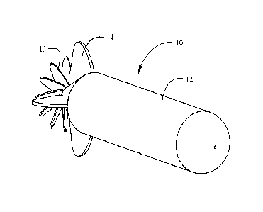
Referring to the drawings, FIG. IA shows a first implementation of the UEHD
10.
The UEHD 10 has a primary hull 12 and is maneuvered (e.g. navigated) through
an ocean
environment with a propulsor 13 (shown as a standard multi-bladed screw as
exemplary) and
control planes 14 (e.g. control fins or hydrodynamic control surfaces)
pivotally connected to
the primary hull 12 for directional control of the UEHD 10. As seen in FIG.
2A, an internal
storage tank 16, which is fillable with cold ocean water as will be described
subsequently, is
employed as a thermal transfer element. The internal storage tank 16 is
substantially
concentric within the primary hull 12 for the implementation shown and a
plurality of
thermoelectric modules 18 are mounted between the internal storage tank 16 and
the primary
hull 12 with a first operational surface 20 on each thermoelectric module 18
in thermal
contact with the primary hull 12 and a second operational surface 22 in
thermal contact with
the internal storage tank 16. The thermoelectric modules may be selected from
at least one of
a Peltier junction device (Seebeck, Thompson effects) and a Sterling engine. A
temperature
differential between the primary hull 12 and the internal storage tank 16 will
provide a
thermal gradient for operation of the thermoelectric modules 18.
The UEHD of FIG. 2A is substantially circular in the central cross section
shown. An
exemplary alternative implementation is shown in FIG. 2B wherein the central
cross section
is rectangular in shape with both the primary hull 12' and internal storage
tank 16' having a
CA 3029964 2019-01-14 -3-
rectangular cross section. The thermoelectric modules 18 are mounted
intermediate the flat
sides 17 of the storage tank 16' and the flat inner sides 19 of the primary
hull 12' to achieve
the desired thermal gradient.
As seen in FIG. 3, the primary hull 12 houses an electrical motor 24 for the
propulsor
13 and a control system 26 for operation and navigation of the UEHD 10. In
particular,
control system 26 operates both the propulsor 13 and one or more of the
control planes 14 to
propel and navigate UEHD 10 through water. An electrical power storage device
28, which
may be a rechargeable battery including a single battery element, a bank of
storage batteries
such as Lithium Ion, Lithium Ion Polymer, Nickel Cadmium, Nickel Metal
Hydride, Lead
Acid, or a capacitive storage system such as a nano-technology supercapacitor,
is connected
through a voltage transformer circuit 30 to the thermoelectric modules 18 and
the motor 24.
Electrical power for the control system 26 may also be provided from the
electrical power
storage device 28.
The exemplary implementation shown in FIG. 3 has an inlet scoop 32 and a vent
34
connecting the internal storage tank 16 with ocean water on the exterior of
the primary hull
12. The inlet scoop 32 and the vent 34 may be retractable or incorporate door
closures for
open and closed positions to allow selective fluid communication with the
external ocean
water. A pump 36 powered by the electrical power storage device 28 may be
employed to
pump water into the internal storage tank 16 from the inlet scoop 32 and out
the vent 34 to
exchange the water in the internal storage tank. Alternatively, the inlet
scoop 32 and vent 34
may be opened to the external ocean water with the UEHD 10 underway allowing
dynamic
pressure of the water to create the flow through the internal storage tank 16.
With the inlet
scoop 32 and vent 34 in the closed position cold ocean water entrained into
the internal
storage tank 16 is stored.
In operation, the UEHD 10 is navigated either autonomously or remotely by the
control system 26 pursuant to a navigational profile (included as a portion of
the
mission/operation profile) to locations of hydrothermal vents near the ocean
floor. A global
distribution of hydrothermal vent fields is present throughout the world's
oceans. Such
thermal vents produce hot water plumes ranging in temperature from 60 to 646
C. With the
UEHD 10 in open water the inlet scoop 32 and vent 34 are deployed or opened in
a first
position of the internal storage tank 16 and cold ocean water is entrained
into the internal
storage tank 16 and then held by closing the inlet scoop 32 and vent 34
placing the internal
storage tank 16 in a second position to store the cold ocean water. With the
UEHD at
submerged depths of 500 meters and below water temperatures of 12 C to 4 C or
less are
CA 3029964 3029964 2019-01-14
available. The UEHD 10 is then navigated by the control system 26 to locate
the primary hull
12 in a hydrothermal vent and either loiters in the hot plume of the vent or
tracks the vent
plume current to remain with the primary hull 12 positioned in a "hot zone"
compared to
surrounding ocean water and the initial temperature of the water stored in the
internal storage
tank 16. The temperature differential of the hot plume in convective and
conductive contact
with the primary hull 12 and the cold water stored with the internal storage
tank 16 acting as
a thermal capacitor provides a thei ma] gradient for operation of the
thermoelectric modules
18 which generate power to charge the electrical power storage device 28.
Operation of the
thermoelectric modules will create warming of the water in the internal
storage tank 16.
When the temperature differential between the external vent plume and internal
storage tank
is decreased to a point where effective power generation by the thermoelectric
modules
ceases, the UEHD 10 is maneuvered by the control system 26 into open water and
the
internal storage tank 16 is exhausted and refilled by operation of the inlet
scoop 32 and vent
34. The UEHD 10 may then be repositioned within the vent plume or moved to a
different
vent plume as necessary for recharging of the electrical power storage device
28. Between
charging cycles, the UEHD 10 may be operated by the control system 26 on its
intended
mission profile.
Alternatively, the thermal gradient may be reversed by navigating the UEHD 10
into
the plume of the thermal vent and opening the inlet scoop 32 and vent 34 to
entrain hot water
from the plume. The UEHD 10 is then navigated by the control system 26 into
open cold
ocean water and the temperature differential of the cold ocean water in
convective and
conductive contact with the primary hull 12 and the hot water from the plume
stored with the
internal storage tank 16 acting as a thermal capacitor provides a reversed
thermal gradient for
operation of the themioelectric modules 18 which generate power to charge the
electrical
power storage device 28. Voltage transformer circuit 30 may be adapted to
sense reversed
current produced by the thermoelectric modules based on the reversed thermal
gradient and
provide rectification for charging of the electric power storage device 28.
Operation of the
thermoelectric modules will create cooling of the water in the internal
storage tank 16. When
the temperature differential between the internal storage tank and the
external ocean water in
contact with the primary hull 12 is decreased to a point where effective power
generation by
the thermoelectric modules ceases, the UEHD 10 is maneuvered by the control
system 26
back to a thermal vent and the internal storage tank 16 is exhausted and
refilled by operation
of the inlet scoop 32 and vent 34.
CA 3029964 3029964 2019-01-14
The systems provided in the UEHD 10 allows "surfing" between hydrothermal
vents
to provide recharging of the electrical power storage device 28 for
substantially uninterrupted
operation in the mission profile. As described, the mission (e.g. operation)
profile can
include activities such as exploration, environmental monitoring and security
operations.
Depending on the size of the UEHD 10 and other considerations, an orienting
ballast
tank 38 may be employed with appropriate control valves 40 and a pump or other
venting
system (including in an exemplary implementation use of the pump 36) to alter
ballast of the
UEHD 10 to selectively induce a vertical, or "pogo" orientation as shown in
FIG. 4. The
UEHD 10 may be maneuvered into the hydrothermal vent plume 42 and reoriented
to the
pogo position by filling the ballast tank 38 to provide greater exposure of
the primary hull 12
to the vent plume if the internal storage tank 16 has been filled cold ocean
water. Upon
completion of the thermoelectric charging cycle or depletion of the
temperature differential in
the internal storage tank 16, water is expelled from the ballast tank 38 and
the UEHD 10 is
reoriented to its conventional operating orientation to provide normal
cruising capability.
The pogo orientation may also be employed to assist in filling the internal
storage tank 16
with water from the plume if a negative temperature differential between the
primary hull 12
and internal storage tank 16 is employed for the charging cycle.
As seen in FIG. 5, the control system 26 incorporates a navigation system 502
that
may be preloaded with a specific mission (e.g. operation) profile 503 for
autonomous
operation using input from a Global Positioning System (GPS) 504 or GPS
sensors, inertial
navigation (e.g. guidance) systems 506 or comparable navigation elements, or
may be
controlled remotely with a communications module 508 and a remote control
system 509.
Artificial intelligence (AI) may be incorporated in a control processor 510
for maneuvering
or loitering within specified parameters in the mission profile. Control
signals for physical
control of the UEHD 10 by the control system 26 are provided through a motor
controller 512
connected to the motor 24 and control planes actuation system 514 connected to
the control
planes 14.
FIG. 1B demonstrates a second implementation of an UEHD 110. As with the first
implementation, the UEHD 110 has a primary hull 112 and is maneuvered through
an ocean
environment with a propulsor 113 (shown as a standard multi-bladed screw as
exemplary)
and control planes 114. The thermal transfer element of the second
implementation is a heat
dissipater 116 mounted to and extending from a top surface 117 of the primary
hull 112. The
heat dissipater 116 may be telescopically extendible for increased surface
area. As seen in
FIG. 6, the primary hull 112 houses a motor 124 for the propulsor 113 and a
control system
CA 3029964 3029964 2019-01-14
126 for operation of the UEHD 110. An electrical power storage device 128,
which may be a
single battery element, a bank of storage batteries such as Lithium Ion,
Lithium Ion Polymer,
Nickel Cadmium, Nickel Metal Hydride, Lead Acid, or a capacitive storage
system such as a
nano-technology supercapacitor, is connected through a voltage transformer
circuit 130 to the
thermoelectric modules 118 and the motor 124. Electrical power for the control
system 126
may also be provided from the electrical power storage device 128.
Thermoelectric modules
118 are connected with a first operational surface 120 on each thermoelectric
module 118 in
thermal contact with the primary hull 112 and a second operational surface 122
in thermal
contact with the heat dissipater 116.
In operation of the second implementation as represented in FIGs. 7A-7C, UEHD
110
cruises in a submerged condition as shown in FIG. 7A pursuant to a mission
profile
established by the control system 126. Anticipated operation for the second
implementation
occurs in artic waters where ocean water temperature is relative constant, at
least -2 C or
warmer while air temperatures, particularly at night, are significantly colder
(approximately -
20 C but ranging from about -60 to -10 C). When charging of the electrical
power storage
device 128 is required, control system 126 causes the UEHD 110 to surface as
shown in FIG.
7B selectively exposing the heat dissipater 116 from the ocean water to the
air. Temperature
differential between the primary hull 112 immersed in ocean water 140 and the
beat
dissipater 116 in convective contact with surrounding air 142 is significant
and sufficient for
operation of the thermoelectric modules 118 to provide electrical energy
generation for
charging of the electrical power storage device. Upon completion of charging
or as otherwise
operationally desirable, the control system 126 causes the UEHD 110 to
submerge for
continuing operation as seen in FIG. 7C.
Various ballast tanks and associated operational systems for providing depth
control
of the disclosed implementations of the UEHD for diving, surfacing and desired
operational
depth are well known in the art and not described herein.
An alternative structural arrangement for the second implementation is shown
in
FIGs. 8A and 8B. As seen in FIG. 8A, UEHD 210 incorporates a primary hull 212
which has
an upper portion 212a and a lower portion 212b separated by an insulating
barrier 213. While
the hull portions 212a, 212b are shown as symmetrical above and below the
insulating barrier
213 non-symmetrical arrangements may be employed. As seen in FIG. 8B,
thermoelectric
modules 218 are engaged with a first operational surface 220 on each
thermoelectric module
218 in thermal contact the upper portion 212a and a second operational surface
222 in
thermal contact with the lower portion 212b. A transfer plate 214 or other
thermally
CA 3029964 2019-01-14 -7-
conductive element may be employed for effective contact between the second
operational
surface 222 and the lower portion 212b or conversely between the first
operational surface
220 and the upper portion 212a. As in the first structural arrangement, UEHD
210
incorporates a power storage device 228, voltage transformer circuit 230,
motor 224 and
control system 226. The UEHD 210 operates in a manner similar to the UEHD 110,
surfacing
to expose the upper portion 212a of the primary hull 212 to the air is a heat
dissipater.
With either structural arrangement of the second implementation, the UEHD 110,
210
thermal transfer through the thermoelectric modules 118, 218 may be reversed
if the air
temperature is warmer than the water temperature thereby providing a reverse
thermal
gradient. When a reverse temperature gradient occurs the electrical current
generated by the
thermoelectric modules 118, 218 reverses direction. A diode circuit within the
voltage
transformer circuit 130, 230 is used to capture the reversed current and then
store the charge
in the electrical power storage device 128, 228.
The implementations of the UEHD as disclosed provide methods for operation of
a
UUV. As shown in FIG. 9 (with reference to FIGs. lA and 3), the UEHD 10 is
navigated
either autonomously or remotely by the control system 26 between locations of
hydrothermal
vents near the ocean floor, step 902.
In a first sequence, with the UEHD 10 in open water the inlet scoop 32 and
vent 34
are deployed or placed in an open position and cold ocean water is entrained
by pumping or
dynamic pressure into the internal storage tank 16 in a first position, step
904, and the inlet
scoop 32 and vent 34 are then closed, step 906, placing the internal storage
tank 16 in a
second position to store the cold ocean water. The UEHD 10 is navigated by the
control
system 26 to a hydrothermal vent location and either loiters with the primary
hull 12 in the
hot plume of the vent or tracks the vent plume current to remain with the
primary hull 12 in a
"hot zone" compared to surrounding ocean water and the initial temperature of
the water in
the internal storage tank 16, step 908. The orienting ballast tank 38 may be
filled, step 910,
orienting the UEHD 10 in a pogo position. In this manner, orienting ballast
tank 38 is filled
for orienting the UEHD in the pogo position. The temperature differential of
the hot plume
in convective and conductive contact with the primary hull 12 and the cold
water stored with
the internal storage tank 16 acting as a thermal capacitor, provides a thermal
gradient for the
thermoelectric modules 18 which are operated based on the thermal gradient
between the
primary hull and internal storage tank to generate power to charge the
electrical power
storage device 28, step 912. The UEHD 10 is maneuvered by the control system
26 into open
CA 3029964 2019-01-14 -8-
water, step 914, and the internal storage tank 16 is exhausted and refilled by
operation of the
inlet scoop 32 and vent 34, step 904, to repeat the process of the first
sequence.
In a second sequence, with the UEHD 10 in the vent plume the orienting ballast
tank
38 may be tilled, step 911, orienting the UEHD 10 in a pogo position. The
inlet scoop 32
and vent 34 are deployed or opened and hot water from the plume is entrained
by pumping or
dynamic pressure into the internal storage tank 16 in the first position, step
905, and the inlet
scoop 32 and vent 34 are then closed, step 907, placing the internal storage
tank 16 in a
second position (e.g. rotated relative to the pogo position) to store the hot
water. The UEHD
is navigated by the control system 26 out of the vent plume and into the open
ocean where
cold water provides a negative temperature differential with respect to the
initial temperature
of the hot water in the internal storage tank 16, step 909. The temperature
differential of the
cold open ocean water in convective and conductive contact with the primary
hull 12 and the
hot water stored with the internal storage tank 16 acting as a thermal
capacitor, provides the
thermal gradient and the thermoelectric modules 18 are operated based on the
thermal
gradient between the primary hull and internal storage tank to generate power
to charge the
electrical power storage device 28, step 913. The UEHD 10 is maneuvered by the
control
system 26 back to a hydrothermal vent plume, step 915, and the internal
storage tank 16 is
exhausted and refilled by operation of the inlet scoop 32 and vent 34, step
905, to repeat the
process of the second sequence. With either sequence, the UEHD may then be
operated in
the desired mission profile, step 916, in concert with navigating and
operating the
thermoelectric modules (18, 118, 218) to charge the electrical power storage
devices (28,
128, 228). The UEHD 10 may be repositioned within the vent plume or moved to a
different
vent plume as necessary for recharging of the electrical power storage device
28 beginning
with step 904, 905.
As shown in FIG. 10 (with reference to FIGs. I B, 6 and 8A-B), the UEHD 110,
210 is
operated submerged on a mission profile directed by the control system 126,
step 1002. When
charging of the electrical power storage device 128 is required, control
system 126 causes the
UEHD 110, 210 to surface, step 1004, exposing the heat dissipater 116, 212a to
the air. The
thermoelectric modules 118 are operated to provide electrical energy
generation for charging
of the electrical power storage device employing temperature differential
between the
primary hull 112 (or 212b) immersed in the ocean water 140 and the heat
dissipater 116, 212a
in convective contact with the surrounding air 142, step 1006. Upon completion
of charging
or as otherwise operationally desirable, the control system 126 causes the
UEHD 110 to
submerge for continuing operation, step 1008.
CA 3029964 3029964 2019-01-14
Having now described various implementations in detail as required by the
patent
statutes, those skilled in the art will recognize modifications and
substitutions to the specific
implementations disclosed herein. Such modifications are within the scope and
intent of the
present invention as defined in the following claims.
CA 3029964 2019-01-14 -10-