Note: Descriptions are shown in the official language in which they were submitted.
CA 03030106 2019-01-07
WO 2018/009193 PCT/US2016/041295
ADJUSTABLE LASER LEVELING DEVICE WITH DISTANCE
MEASURING LASERS AND SELF-LEVELING LASERS AND RELATED
METHOD
FIELD OF INVENTION
[001] The present invention relates to a laser leveling device as generally
described in US Patent Application 14/602,430 (the "'430 Application"), and
specifically
to certain improvements for the laser leveling device, namely: the use of
distance
measuring lasers and a self-leveling laser housing in the laser leveling
device.
BACKGROUND
[002] There are various tools on the market that utilize line lasers. However,
such tools are generally limited to providing reference laser lines and
require the user to
move the tool and interrupt the reference lines in order to complete complex
layouts.
What is needed is a device to facilitate leveling and installation of objects
and fixtures,
such as shelving, home decor, cabinets, and tile, without moving or
interrupting the
device continuously. Further what is needed is a device that allows the user
to make
measurements along the referenced laser lines to facilitate the layouts.
SUMMARY OF INVENTION
[003] The following summary is provided to facilitate an understanding of some
of the innovative features unique to the present invention. The present
invention is not
intended to be limited by this summary or any objectives conveyed herein. Many
possible embodiments of the invention may be made and will be readily evident
upon a
study of the following specification and accompanying drawings comprising a
part
thereof. Various features and subcombinations of invention may be employed
without
1
CA 03030106 2019-01-07
WO 2018/009193 PCT/US2016/041295
reference to other features and subcombinations. Other objects and advantages
of this
invention will become apparent from the following description taken in
connection with
the accompanying drawings, wherein is set forth by way of illustration and
example, an
embodiment of this invention and various features thereof.
[004] The present invention relates to a laser leveling device to facilitate
leveling
and installation of objects and fixtures, such as shelving, cabinets, and home
decor. In
a preferred embodiment, the laser leveling device has one or more bases
capable of
being temporarily affixed to a wall or other work surface, using known
materials such as
removable adhesive tabs, strips, mounting screws, nails, pins, magnets, hooks,
hoop
and loop, or other fasteners now known or hereinafter developed.
[005] A preferred embodiment of this invention includes a plurality of
distance
measuring lasers located at predetermined angles in one or more of the bases.
A base
containing the plurality of distance measuring lasers is located over a
predetermined
reference point on a wall or other work surface (the datum point). A datum
point as
used herein means an initial predetermined reference point on a wall or other
work
surface and any other reference points identified on the wall or other work
surface using
the laser leveling device. By placing the laser leveling device over a datum
point, a user
is able to identify and mark additional points on the wall or other work
surface for laying
out a project. The distance measuring lasers are connected to a power source
and a
circuit board, or other computer processor, which includes wireless
communication
capability. When the distance measuring lasers are powered on, a user is able
to
determine the distance from the datum point using a handheld display that
communicates with the distance measuring lasers using Bluetooth or other
wireless
2
CA 03030106 2019-01-07
WO 2018/009193 PCT/US2016/041295
communications now known in the industry or hereinafter developed. The
handheld
display is used to interchangeably interrupt the laser beam emitted from one
of the
distance measuring lasers, causing the distance from the datum point to the
leading
edge of the handheld display to be calculated by the computer processor for
the
distance measuring lasers, and then communicated to and displayed by the
handheld
display. The handheld display, in some embodiments is a smartphone or other
mobile
device with a software application and the ability to communicate wirelessly
with the
distance measuring lasers. When using a smartphone as the handheld display, a
software application on the smartphone allows the distance measurements to be
communicated to and displayed on the smartphone when the emitted laser beam
from
one of the distance measuring lasers is interrupted. The smartphone or mobile
device,
in some embodiments includes an attachment to facilitate interruption of the
emitted
laser beam from the distance measuring laser and marking distances on the wall
or
other work surface. For example, in some embodiments an adjustable sled is
used for
a smartphone to facilitate moving the smartphone along the beam emitted from
the
distance measuring laser and to interrupt the beam. The distance between the
datum
point at the center of the base and the leading edge of the adjustable sled
containing
the smartphone is displayed in real time on the smartphone.
[006] The inclusion of distance measuring lasers allows the user to measure
distances from the center of a base placed over a datum point without using a
tape
measure or other distance measuring tool.
[007] In an alternative embodiment, a single distance measuring laser is
rotatably attached to a base, allowing the distance measuring laser to be
rotated to
3
CA 03030106 2019-01-07
WO 2018/009193 PCT/US2016/041295
different angles for measuring distances from the datum point using the
handheld
display. In a further alternative embodiment, one or more distance measuring
lasers is
mounted on the laser assembly of the laser leveling device. In another
embodiment,
the handheld display includes other functionality such as a stud finder.
[008] The laser leveling device of this invention includes a laser assembly
that is
capable of being removably and interchangeably attached to any of the
plurality of
bases. In a preferred embodiment, the laser assembly contains a plurality of
lasers
arranged at predetermined angles, including orthogonal angles, allowing laser
lines to
be emitted from multiple sides of the laser assembly and projected onto a wall
or other
work surface so that the laser lines are visible to the user.
[009] In a preferred embodiment of the present invention, the laser assembly
includes a means for leveling the lasers in the laser assembly. In the present
invention,
a preferred method for leveling the lasers in the laser assembly is the use of
a self-
leveling laser housing. However, in other embodiments, other means will be
used
including manual leveling of the lasers using a torpedo level. In one such
preferred
embodiment, the lasers are adjustably mounted to the housing. The housing is
movably
attachable to the top side of the laser assembly, creating a pendulum that
will swing
freely when the laser assembly is engaged to a base attached to a vertical
work
surface. The self-leveling laser housing in some embodiments will include
means for
balancing the self-leveling laser housing and adjusting the roll, pitch, and
yaw of each of
the plurality of lasers in the housing to allow the lasers to level once the
laser assembly
is engaged with a base on a wall or other vertical work surface. A preferred
embodiment of the self-leveling laser housing also includes a prism positioned
in the
4
CA 03030106 2019-01-07
WO 2018/009193 PCT/US2016/041295
path of each of the plurality of lasers that causes a level, visible beam from
each said
laser to project as lines on the work surface.
[010] The present invention advantageously allows level visible laser lines to
be
established, broadcast, and projected onto a wall or other work surface while
the user
makes multiple layout marks. More particularly, the present invention
facilitates leveling
and arrangement of objects on a wall or other work surface by allowing the
user to
easily measure distances from a datum point to additional points in the
layout, along
level, visible laser lines projected onto the work surface. Additional bases
may be
placed over other reference points on the work surface, which reference points
originate
from the initial datum point. The use of more than one base in any layout
allows the
laser assembly to be moved from base to base effectively and efficiently
within said
layout field without interrupting previously identified marks in the layout.
[011] An alternative embodiment of the present invention is a laser leveling
device with a base that is capable of being removably affixed to a wall or
other work
surface and one or more distance measuring lasers rotatably mounted to said
the base,
wherein the user is able to rotatably adjust the distance measuring lasers to
orient the
lasers to a desired position for measuring distances in various directions and
at various
angles from the center of the base.
[012] A further alternative embodiment of the present invention is a laser
assembly with one or more lasers where the laser assembly is rotatably and
removably
attached to a base, wherein the user is able to rotatably adjust the laser
assembly on
said base to orient the lasers in the laser assembly to a desired position.
WO 2018/009193
ACT/US2016/041295
[013] In a further alternative embodiment, the laser assembly and a base are
coupled
together to form a single integrated device.
[014] Unless otherwise defined, all technical terms used herein have the same
meaning as commonly understood by one of ordinary skill in the art to which
this invention
belongs. Although methods and materials similar or equivalent to those
described herein
can be used in the practice or testing of the present invention, suitable
methods and
materials are described below.
DESCRIPTION OF DRAWINGS
[015] The accompanying figures are incorporated herein and form a part of the
specification for the present invention and further illustrate the present
invention:
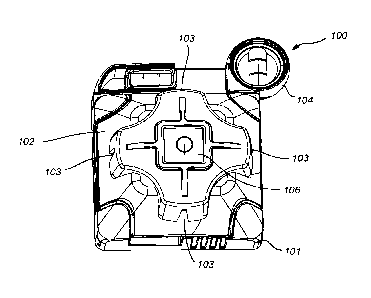
FIG. 1 is a top view of the laser leveling device, according to an embodiment
of
the present invention.
FIG. 2 is an exploded view of the laser leveling device showing the laser
assembly, distance measuring lasers located near the center of the base, and
the
handheld display for measuring distances from the center of the base,
according to an
embodiment of the present invention.
FIG. 3 is a top view of a base for the laser leveling device, showing distance
measuring lasers located near the center of said base and the handheld display
for
measuring distances from the center of the base, according to an embodiment of
the present invention.
6
Date Recue/Date Received 2023-01-13
CA 03030106 2019-01-07
WO 2018/009193 PCT/US2016/041295
FIG. 4 is a top view of a base for the laser leveling device, showing
distance measuring lasers located near the center of said base and a
smartphone with attachment used for measuring distances from the center of the
base, according to an embodiment of the present invention.
FIG. 5 is a perspective view of a laser assembly of the laser leveling
device, according to an embodiment of the present invention.
FIG. 6 is an exploded view of a laser assembly of the laser leveling device
with a self-leveling laser housing and lasers, according to an embodiment of
the
present invention.
FIG. 7 is a perspective top view of a self-leveling laser housing with lasers,
according to an embodiment of the present invention.
FIG. 8 is a perspective bottom view of a self-leveling laser housing with
lasers, according to an embodiment of the present invention.
FIG. 9 is an exploded view of the self-leveling laser housing and lasers,
according to an embodiment of the present invention.
FIG. 10 is perspective view of an alternative member of the self-leveling
laser housing providing for multi-axis adjustment of the pendulum.
DETAILED DESCRIPTION OF INVENTION
[016] The present invention is best understood by reference to the drawings
and
description set forth herein. Embodiments of the invention are discussed below
with
reference to the drawings. However, those skilled in the art will readily
appreciate that
the detailed description given herein with respect to the drawings is for
explanatory
purposes as the invention extends beyond the limited embodiments described.
For
7
CA 03030106 2019-01-07
WO 2018/009193 PCT/US2016/041295
example, in light of the teachings of the present invention, those skilled in
the art will
recognize a multitude of alternate and suitable approaches, depending upon the
needs
of the particular application, to implement the functionality of any given
detail described
herein beyond the particular implementation choices in the following
embodiments
described and shown. Numerous modifications and variations of the invention
exist,
which are too numerous to be listed but that all fit within the scope of the
invention.
Also, singular words should be read as plural and vice versa and masculine as
feminine
and vice versa, where appropriate, and alternative embodiments do not
necessarily
imply that the two are mutually exclusive.
[017] The present invention should not be limited to the particular
methodology,
compounds, materials, manufacturing techniques, uses, and applications,
described
herein, as these may vary. The terminology used herein is used for the purpose
of
describing particular embodiments only, and is not intended to limit the scope
of the
present invention. As used herein and in the appended claims, the singular
forms "a,"
"an," and "the" include the plural reference unless the context clearly
dictates otherwise.
Thus, for example, a reference to "an element" is a reference to one or more
elements
and includes equivalents thereof known to those skilled in the art. Similarly,
for another
example, a reference to "a step" or "a means" may be a reference to one or
more steps
or means and may include sub-steps and subservient means.
[018] All conjunctions used herein are to be understood in the most inclusive
sense possible. Thus, a group of items linked with the conjunction "and"
should not be
read as requiring that each and every one of those items be present in the
grouping, but
rather should be read as "and/or" unless expressly stated otherwise.
Similarly, a group
8
CA 03030106 2019-01-07
WO 2018/009193 PCT/US2016/041295
of items linked with the conjunction "or" should not be read as requiring
mutual
exclusivity among that group, but rather should be read as "and/or" unless
expressly
stated otherwise. Structures described herein are to be understood also to
refer to
functional equivalents of such structures. Language that may be construed to
express
approximation should be so understood unless the context clearly dictates
otherwise.
[019] Unless otherwise defined, all terms (including technical and scientific
terms) are to be given their ordinary and customary meaning to a person of
ordinary
skill in the art, and are not to be limited to a special or customized meaning
unless
expressly so defined herein.
[020] Terms and phrases used in this application, and variations thereof,
especially in the appended claims, unless otherwise expressly stated, should
be
construed as open ended as opposed to limiting. As examples of the foregoing,
the
term "including" should be read to mean "including, without limitation,"
"including but not
limited to," or the like; the term "having" should be interpreted as "having
at least"; the
term "includes" should be interpreted as "includes but is not limited to"; the
term
"example" is used to provide exemplary instances of the item in discussion,
not an
exhaustive or limiting list thereof; and use of terms like "preferably,"
"preferred,"
"desired," "desirable," or "exemplary" and words of similar meaning should not
be
understood as implying that certain features are critical, essential, or even
important to
the structure or function of the invention, but instead as merely intended to
highlight
alternative or additional features that may or may not be utilized in a
particular
embodiment of the invention.
9
CA 03030106 2019-01-07
WO 2018/009193 PCT/US2016/041295
[021] Those skilled in the art will also understand that if a specific number
for a
claim recitation is intended, such an intent will be explicitly recited in the
claim, and in
the absence of such recitation no such intent is present. For example, as an
aid to
understanding, the appended claims may contain usage of the introductory
phrases "at
least one" and "one or more" to introduce claim recitations. However, the use
of such
phrases should not be construed to imply a claim recitation by the indefinite
articles "a"
or "an" limits any particular claim containing such claim recitation to
embodiments
containing only one such recitation, even when the same claim includes the
introductory
phrases "one or more" or "at least one" and indefinite articles such as "a" or
"an" (e.g.,
"a" and "an" should typically be interpreted to mean "at least one" or "one or
more"); the
same holds true for the use of definite articles used to introduce claim
recitations. In
addition, even if a specific number of claim recitations is explicitly
recited, those skilled
in the art will recognize that such recitation should typically be interpreted
to mean at
least the recited number (e.g., the bare recitation of "two recitations,"
without other
modifiers, typically means at least two recitations, or two or more
recitations).
Furthermore, in those instances where a convention analogous to "at least one
of A, B,
and C" is used, in general, such a construction is intended in the sense one
having skill
in the art would understand the convention (e.g., "a system having at least
one of A, B,
and C" would include but not be limited to systems that have A alone, B alone,
C alone,
A and B together, A and C together, B and C together, and/or A, B, and C
together,
etc.).
[022] All numbers expressing dimensions, quantities of ingredients, reaction
conditions, and so forth used in the specification are to be understood as
being modified
CA 03030106 2019-01-07
WO 2018/009193 PCT/US2016/041295
in all instances by the term "about" unless expressly stated otherwise.
Accordingly,
unless indicated to the contrary, the numerical parameters set forth herein
are
approximations that may vary depending upon the desired properties sought to
be
obtained.
[023] Throughout this disclosure, examples will be provided for using the
laser
leveling device. However, those skilled in the art will appreciate additional
applications
for the laser leveling device. Uses of the present invention may relate to,
for example,
hanging shelving, pictures, collages, art work, closet shelving, decorative
shelving,
curtain rods, towel bars, fixed hang holes, tile work, cabinets, built-in
cabinets/shelving,
kitchen cabinets, door hardware, wall mounted lighting fixtures, flat screen
TV mounts,
and other installations.
[024] The invention provides a laser leveling device characterized by one or
more horizontal and/or vertical lasers integrated into a laser assembly. The
lasers in
the laser assembly are self-leveling and project level laser lines onto a work
surface
when the laser leveling device is removably attached to the work surface. The
laser
leveling device includes one or more bases to which the laser assembly is
capable of
being removably and interchangeably attached. One or more of the bases for the
laser
leveling device contain one or more distance measuring lasers that allow the
user to
measure distances from the center of the base along the laser lines projected
by the
laser assembly along on the work surface. Alternatively, the distance
measuring lasers
in some embodiments are mounted onto or within the laser assembly.
[025] In a preferred embodiment, the laser leveling device has a plurality of
bases with one or more distance measuring lasers mounted on one or more of
said
11
CA 03030106 2019-01-07
WO 2018/009193 PCT/US2016/041295
bases. The distance measuring lasers on said bases are connected to a power
source
and a circuit board, or other computer processor, which includes wireless
communication capability. When a base containing the one or more distance
measuring lasers is placed over a datum point and the distance measuring
lasers are
powered on, a user is able to determine the distance from the datum point
using a
handheld display that communicates with the distance measuring lasers using
Bluetooth
or other wireless communications now known in the industry or hereinafter
developed.
The handheld display is used to interchangeably interrupt the laser beam
emitted from
one of the distance measuring lasers, causing the distance from the datum
point to the
leading edge of the handheld display to be calculated by the computer
processor for the
distance measuring lasers, and then communicated to and displayed by the
handheld
display. In a preferred embodiment, the handheld display has wireless
connectivity with
the distance measuring lasers in one of the plurality of bases using Bluetooth
or other
wireless communication. The handheld display also has LCD readout for
displaying
measurements. In a preferred embodiment, the handheld display provides a
continuous
readout of distances as it is moved along the distance measuring laser. The
handheld
display in some embodiments is a smartphone or other mobile device with a
software
application for calculating and displaying distances when the laser beam
emitted from a
distance measuring laser is interrupted. The handheld display may also include
other
functions, such as a stud finder. In some embodiments, another object, device,
or tool
is used to interrupt the distance measuring laser, causing the distance to be
displayed
on the handheld device or on a separate display in close proximity to the
distance
measuring lasers.
12
CA 03030106 2019-01-07
WO 2018/009193 PCT/US2016/041295
[026] In an alternative embodiment, one or more distance measuring lasers is
rotatably and removably attached to a base, allowing the distance measuring
device to
be rotated to different angles for measuring distances from the center of said
base.
[027] In a preferred embodiment, each of the plurality of bases is capable of
being removably affixed to the work surface, using known materials such as
removable
adhesive tabs, strips, mounting screws, nails, pins, hooks, magnets, hoop and
loop, or
other known fasteners. Each of the plurality of bases has a bull's-eye-like,
open hole at
the center, allowing the user to align each of the bases over datum points on
the work
surface. Alternatively, each of the bases is capable of being aligned over
datum points
using other means, such as magnets or sensors placed on the work surface.
[028] In a preferred embodiment, the laser leveling device includes a laser
assembly that is capable of being removably and interchangeably attached to
any of the
plurality of bases. Said laser assembly contains a plurality of lasers
arranged at
preferred angles, including orthogonal angles, allowing laser lines to be
emitted out of
multiple sides of the laser leveling device and projected onto a wall or other
work
surface. In the preferred embodiment, the lasers in the laser assembly are
self-leveling.
A preferred embodiment of the self-leveling lasers includes mounting the
plurality of
lasers in a housing that is movably attached to the top side of the laser
assembly (when
mounted on a base attached to a work surface), thereby creating a pendulum for
the
housing containing the plurality of lasers. When the laser assembly with the
self-
leveling laser housing is attached to a base on a work surface, the self-
leveling laser
housing swings freely, leveling the lasers. The self-leveling laser housing
also includes
means for balancing the self-leveling laser housing and adjusting roll, pitch,
and yaw of
13
CA 03030106 2019-01-07
WO 2018/009193 PCT/US2016/041295
the lasers mounted to the housing to ensure that the lasers will level
automatically when
attached to a work surface. The preferred embodiment of the self-leveling
laser housing
also includes a prism positioned in the path of each of the plurality of
lasers mounted to
the housing. The beams from each of the lasers pass through the prism causing
the
beams to be projected onto the work surface when the laser assembly is
attached to a
base mounted on the work surface.
[029] The present invention advantageously allows level laser lines to be
established, broadcast, and held on a work surface while the user makes
multiple layout
marks. More particularly, the present invention facilitates leveling and
arrangement of
objects on a wall or other work surface by allowing the user to easily move
the laser
assembly to a plurality of bases attached to the work surface to facilitate
and expedite
making multiple layout marks on the work surface and thereby successfully
laying out a
project.
[030] To illustrate embodiments of the present invention, reference is made to
the drawings. FIG. 1 shows a top view of a preferred embodiment of the laser
leveling
device 100 of the present invention and specifically shows a base 101, the
laser
assembly 102 with four lasers 103 installed at orthogonal angles in the laser
assembly
102. FIG. 1 also shows a power button 106 for powering on one or more of the
lasers
103, and a level assembly 104 that is removably attached to the base of the
laser
leveling device 100. In this embodiment, having four sides, a laser line is
capable of
being emitted from each side of the laser assembly 102 with laser lines
emitted at
predetermined angles, including orthogonal angles, across the wall or other
work
surface. In a preferred embodiment, the laser leveling device 100 includes a
plurality of
14
CA 03030106 2019-01-07
WO 2018/009193 PCT/US2016/041295
bases 101. The use of multiple bases 101 allows a user to expand layout
possibilities
by aligning the bases 101 over datum points on a work surface and then moving
the
laser assembly 102 from base 101 to base 101 to provide additional reference
lines. In
a preferred embodiment, bases 101 include openings that allow laser lines to
pass
through, over, and/or underneath the bases 101 for accurate alignment of the
bases
101 and assistance with creating a grid of leveled laser lines on a work
surface.
[031] FIG. 2 is a perspective, exploded view of a preferred embodiment of a
laser leveling device 100 of the present invention, including a base 101, a
laser
assembly 102, which is removably attachable to the base 101 by aligning the
corner
depressions 110 to the pillars 108 on the base 101. FIG. 2 also shows a
plurality of
distance measuring lasers 150 located at or near the center of the base 101.
The
distance measuring lasers 150 are connected to a power source and a circuit
board, or
other computer processor, which includes wireless communication capability.
The
power source and circuit board are located on the base 101 with the distance
measuring lasers 150, but are not shown in FIG. 2. In a preferred embodiment,
the
computer processor connected to the distance measuring lasers 150 calibrates
the
distance measuring lasers so that distances are measured from the center of
the base
101 when the base 101 is located over a datum point. FIG. 2 further shows a
handheld
display 151 that wirelessly communicates with the plurality of distance
measuring lasers
150 using Blue Tooth or other means known in the art. Distances are measured
from
the center of the base 101 by identifying the direction in which the
measurement is to be
made, powering on the distance measuring laser 150 aligned in said direction
and
interrupting the beam emitted 166 from one of the distance measuring lasers
150 using
CA 03030106 2019-01-07
WO 2018/009193 PCT/US2016/041295
the handheld display 151. When the beam from the distance measuring laser 150
is
interrupted, the handheld display 151 will display in real time the distance
from the
center of the base 101. In a preferred embodiment, the distance measuring
lasers 150
are not visible to the human eye, will not project onto the work surface, and
will not
disrupt or interfere with the visibility of the lasers 103 of the laser
assembly 102, which
will project onto the work surface.
[032] FIG. 2 also shows a bull's-eye opening 107 at the center of the base 101
to facilitate locating the base 101 over a datum point. FIG. 2 also shows a
laser
assembly 102 with lasers 103, a power button 106 for the lasers 103 in the
laser
assembly 102 and corner depressions 110 for aligning and removably attaching
the
laser assembly 102 to the base 101. In a preferred embodiment, when the laser
assembly 102 is removably attached to a base 101 that is removably mounted
onto the
work surface and the lasers 103 in the laser assembly 102 are activated, the
lasers 103
will emit and project visible, level laser lines onto the work surface.
[033] FIG. 2 further shows a level assembly 104, comprising a torpedo level
with
both horizontal 115 and vertical 116 vials for leveling the base 101 and thus
the laser
lines emitted from a laser assembly 102. The level assembly 104 is capable of
being
removably attachable to a base 101 or located adjacent to a base 101 using
magnets,
Velcro, or other fasteners. The level assembly 104 is capable of being used to
manually level a base 101 when it is removably attached to a work surface or
to level
the entire laser leveling device 100 that is attached to a work surface.
[034] FIG. 3 is a top view of a base 101 showing a plurality of distance
measuring lasers 150 located at or near the center of the base 101. FIG. 3
also shows
16
CA 03030106 2019-01-07
WO 2018/009193 PCT/US2016/041295
a bull's eye opening 107 at the center of the base 101 for positioning the
base 101 over
a datum point on a work surface and four pillars 108 that receive and secure
the laser
assembly 102 to the base 101.
[035] Using the computer processor connected to the distance measuring lasers
150, each of the distance measuring lasers is calibrated to provide distance
measurements from the center of the base 101. When the base 101 is centered
over a
datum point, the distance from the datum point is measured. Included with the
distance
measuring lasers 150 on the base 101 are electronics (not shown in FIG. 3)
known to
one skilled in the art such as batteries or other sources of power for the
distance
measuring lasers 150, a power switch, a circuit board or other computer
processor, and
a means for wirelessly communicating with the handheld display 151. Distances
are
measured from the center of the base 101 located over a datum point on the
work
surface by powering on the distance measuring lasers 150, selecting the
desired
direction for measuring distance from the center of the base 101 and
interrupting the
laser beam emitted 166 from the distance measuring laser 150 pointed in said
direction
using the handheld display 151. The handheld display has a LCD display or
other
similar display, other electronic components known in the art, and
communicates with
the distance measuring lasers 150 using Bluetooth or other means of wireless
communication. When the handheld display 151 interrupts the selected distance
measuring laser 150 the distance from the center of the base 101 is calculated
and
displayed on the LCD screen of the handheld display 151. When the handheld
display
151 is moved along the emitted laser beam 166 for the selected distance
measuring
17
CA 03030106 2019-01-07
WO 2018/009193 PCT/US2016/041295
laser 150 the distance from the center of the base 101 will be displayed
continuously
and in real-time.
[036] In an alternative embodiment, as shown in FIG. 4, the handheld display
is
a smartphone or other mobile device 165 that communicates by Blue Tooth or
other
wireless means with the distance measuring lasers 150 and includes a software
application 161 that allows the smartphone 165 to calibrate and display
distances from
the center of the base 101 when the emitted laser beam 166 is interrupted. In
such
embodiment, a user may attach a side rail or an adjustable cradle 162 to the
smartphone 165 to facilitate interruption of the beam from one of the distance
measuring lasers 150 and assist in placing marks on the work surface.
[037] In a preferred embodiment of the present invention, the distance
measuring lasers 150 are not projected onto the work surface and are not
generally
visible to the user. In such preferred embodiment, the distance measuring
lasers 150
are installed in one or more bases 101 and are aligned on the same axes as the
lasers
103 installed in the laser assembly 102. The lasers 103 in the laser assembly
are
projected onto the work surface and as such are visible to the user. In this
preferred
embodiment, the user is able to measure distances along the projected laser
lines on
the work surface by moving the handheld display 151 along the projected laser
lines
thereby interrupting the beam from the distance measuring lasers 150 that are
aligned
on the same axes as the laser assembly 102 lasers 103. The distance measuring
lasers
150 will operate independently from the lasers 103 in the laser assembly 102.
The
distance measuring lasers 150 are capable of being mounted at or near the
center of
the base 101 on the same axes as the lasers 103 in the laser assembly 102.
18
CA 03030106 2019-01-07
WO 2018/009193 PCT/US2016/041295
Alternatively, one or more distance measuring lasers 150 are capable of being
rotatably
mounted at or near the center of the base 101 to allow the one or more
distance
measuring lasers 150 to be rotatably aligned to the same axes as the lasers
103 in the
laser assembly 102.
[038] In an alternative embodiment, one or more distance measuring lasers 150
is installed on or in the laser assembly 102 and aligned on the same axes as
the lasers
103 projecting onto the work surface. In this embodiment, the distance
measuring
lasers 150 do not necessarily require a separate power source or power button
106 and
are capable of utilizing the power source and power button 106 for the laser
assembly
102. In a further alternative embodiment, the handheld display 151 includes a
stud
finder to allow a user to identify studs in the work surface and measure the
distance
from the center of the base 101 to the stud. In some embodiments, an object,
device,
or tool, other than the handheld display, is used to interrupt the distance
measuring
laser, causing the distance to be displayed on the handheld device or on a
separate
display in close proximity to the distance measuring lasers.
[039] FIG. 5 is a perspective view of a preferred embodiment of the laser
assembly 102 of the present invention. FIG. 5 shows lasers 103 positioned at
right
angles in the laser assembly 102, a power button 106 for powering on and off
the lasers
103 in the laser assembly 102 and corner depressions 110 for aligning and
removably
attaching the laser assembly 102 to a base 101.
[040] FIG. 6 is an exploded view of a preferred embodiment of the laser
assembly 102 of the present invention, showing an upper enclosure 113 of the
laser
assembly 102, a plurality of lasers 103 installed on a housing 152, and a
bottom
19
CA 03030106 2019-01-07
WO 2018/009193 PCT/US2016/041295
enclosure 114 for the laser assembly 102. The laser assembly 102 also includes
batteries or other means for powering the lasers 103 and a power button 106
for
powering the lasers 103 on and off. In a preferred embodiment, the power
button 106 is
capable of being configured to activate an individual laser 103 or multiple
lasers 103.
Alternatively, there is a master power button 106 and a separate control means
(e.g.
circuit configuration and/or processor) for cycling to one of the plurality of
laser 103 the
user wishes to operate. The laser assembly 102 in some embodiments is also
configured with multiple power buttons for different lasers 103. In one
example, without
limitation, a single click of a power button 106 enables horizontal lasers
103, a second
click enables vertical lasers 103, a third click enables all lasers 103, and a
subsequent
click disables all lasers 103.
[041] In a preferred embodiment of the present invention, as shown in FIG. 6,
the lasers 103 in the laser assembly 102 are adjustably mounted and aligned in
a self-
leveling laser housing 152 that is movably attached inside the laser assembly
102 so
that the top 169 of the housing 152 is at the top 170 of the laser assembly
102 when the
laser assembly 102 is attached to a base 101 removably mounted onto a vertical
work
surface. In this embodiment, the housing 152 will swing as a pendulum when the
laser
assembly 102 is attached with a base 101 that is mounted on a wall or other
vertical
work surface. The pendulum action of the housing 152 allows the lasers 103 to
self-
level. FIG. 6 also shows electrical wires 168 for connecting the lasers 103 to
the
electrical components of the laser assembly 102, including batteries or other
power
source and the power button 106.
CA 03030106 2019-01-07
WO 2018/009193 PCT/US2016/041295
[042] FIGS. 7-10 show further details of the self-leveling laser housing 152
of
the present invention. FIG. 7 is a top perspective view of the self-leveling
laser housing
152 showing four lasers 103 mounted and aligned on the housing 152. FIG. 7
also
shows a balance weight adjustment 156 for balancing the housing 152 to ensure
the
pendulum action of the housing 152 is properly balanced. FIG. 7 further shows
screw
adjustments 155 for adjusting the yaw of the mounted lasers 103. In
alternative
embodiments, other known means for adjusting the balance and yaw will be
utilized. In
a preferred embodiment, the pitch and roll of the lasers are set during
assembly and are
not adjustable. In an alternative embodiment, the housing 152 includes
screw
adjustments or other means for adjusting roll 160, pitch 159, and yaw 155 of
the lasers
103 as illustrated in FIG. 10. FIG. 7 also shows electrical wires 168 for
connecting the
lasers 103 to the electrical components of the laser assembly 102, including
batteries or
other power source and the power button 106.
[043] As shown in FIG. 7, a preferred embodiment of the present invention also
includes prisms 157 located in front of each laser 103 in the laser assembly
102. The
prisms 157 cause the emitted laser beams from the lasers 103 to project onto
the work
surface when the lasers 103 are powered on, allowing a user to see a level
laser lines
projected onto the work surface.
[044] FIG. 8 is a back perspective view of the self-leveling laser housing
152,
showing the pivot bearing 158 that movably attaches to the bottom enclosure
114 of the
laser assembly 102, allowing the housing 152 to swing freely as a pendulum
when the
laser assembly 102 is attached to a base 101 that is mounted to a vertical
work surface.
FIG. 8 also shows the lasers 103 adjustably mounted on the housing 152,
balancing
21
CA 03030106 2019-01-07
WO 2018/009193 PCT/US2016/041295
weights 156 to balance the pendulum action of the housing 152, the yaw
adjustments
155 for the lasers 103, and the prisms 157 mounted in front of the lasers 103.
[045] FIG. 9 is an exploded perspective view of the self-leveling laser
housing
152, showing the lasers 103, the yaw adjustments 155, the weight balance
adjustments
156, the pivot bearing 158, and the prisms 157. FIG 10 is a partial view of
the self-
leveling laser housing 152, which shows an alternative embodiment of the
housing 152
utilizing multi-axis adjustments, including pitch adjustments 159, yaw
adjustments 155,
and roll adjustments 160.
[046] In a preferred embodiment of the present invention utilizing the self-
leveling laser housing 152, the laser leveling device 100 contains a master
power button
106 for the laser assembly 102 and a separate button for cycling to different
lasers 103
of the laser assembly 102. When the power button 106 is in the off position,
the
housing 152 is locked in place by a pin or similar fastener and not allowed to
swing as a
pendulum. When the power button 106 is moved to the on position, the housing
152 is
unlocked, allowing it to swing freely as a pendulum and allowing the lasers
103 to self-
level. Once the master power button 106 is turned to the on position, the
separate laser
cycle button is used to cycle on one or more of the lasers 103 in the laser
assembly
102.
[047] In one embodiment of the present invention, a plurality of bases 101 is
utilized with one of the bases 101 arranged on the work surface near laser
lines emitted
from a laser assembly 102 removably attached to another of the plurality of
bases 101
on the work surface. The visible, level laser lines from the laser assembly
102 pass
through an opening in the base 101 or under the base 101 without being
interrupted to
22
CA 03030106 2019-01-07
WO 2018/009193 PCT/US2016/041295
allow for alignment of the bases 101 along the level laser lines. In other
embodiments,
the laser leveling device 100 comprises a plurality of bases 101 and a
plurality of laser
assemblies 102 whereby multiple bases 101 affixed on the work surface have
laser
assemblies 102 removably attached, allowing level, visible laser lines to be
projected
onto the work surface from more than one laser assembly 102 at a time, thereby
creating a visible grid of level laser lines on the work surface to facilitate
project layout.
[048] In other embodiments, a laser assembly 102 is capable of being rotatably
attached to a base 101 allowing the user to set various degrees of laser
orientation from
a base 101 removably attached to a work surface. For example, the center of a
base
101 will rotate on ball bearings, allowing the distance measuring lasers 150
and the
laser assembly 102 to rotate to different angles when attached to the base
101. In
another embodiment, a base 101 includes a center disc or other means for
rotating the
distance measuring lasers 150 and the laser assembly 102 at various degrees
around
the center of the base 101. The distance measuring lasers 150 of various
embodiments
rotate with or separately from the laser assembly 102. When the self-leveling
laser
housing 152 of the present invention is used with a rotating laser assembly
102, the
self-leveling laser housing 152 has a means, such as a pin or screw, for
locking the
housing in place once the lasers 103 are set to the preferred angle and level.
[049] In other embodiments, the laser assembly 102 is capable of being
permanently affixed to a base 101, forming an integrated laser leveling device
100. In
some embodiments, the laser assembly 102 includes lasers at angles other than
orthogonal angles. For example, the lasers may be provided at every 45 degrees
and
other common angles.
23
CA 03030106 2019-01-07
WO 2018/009193 PCT/US2016/041295
[050] The laser leveling device 100 is capable of being configured in various
sizes and shapes. However, a size and shape that can be easily lifted and
moved with
one hand is preferred. For example, in one embodiment, the plurality of bases
101 is
rectangular with a length and width ranging between 2% inches to approximately
5%
inches without limitation. The thickness of the base 101 in one embodiment is
approximately 1/2 inch. A thinner base will be utilized in other embodiments
to ensure
the distance measuring lasers 150 are not too far removed from the work
surface,
advantageously increasing accuracy in measurements along the projected laser
lines.
In a preferred embodiment, the bases 101 and the upper enclosure 113 and
bottom
enclosure 114 of the laser assembly 102 are manufactured from plastic
materials to
provide light weight and ease of use. However, other materials will also be
used in
various embodiment of the invention. In a preferred embodiment, the lasers 103
are
laser diodes, but other lasers will be used in various embodiments of the
invention.
[051] It is to be understood that the foregoing description is intended to
illustrate
and not limit the scope of the invention, which is defined by the scope of the
appended
claims. Other aspects, advantages, and modifications are within the scope of
the
following claims.
24